1
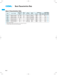
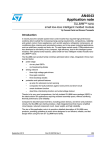
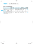
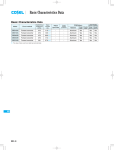
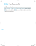
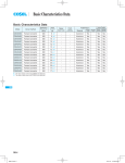
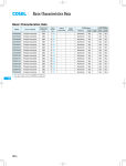
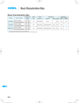
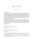
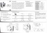
Basic Characteristics Data
Basic Characteristics Data
Switching
Input
frequency
current
[kHz]
*1 [A]
Model
Circuit method
VAF5
Flyback converter
100
VAF10
Flyback converter
100
Material
Single
sided
Series/Parallel
operation availability
Double Series Parallel
sided operation operation
Resistor
CEM-3
Yes
Yes
*2
Resistor
CEM-3
Yes
Yes
*2
Rated
input fuse
Inrush
current
protection
0.15
250V 2A
0.3
250V 2A
PCB/Pattern
*1 The value of input current is at ACIN 100V and rated load.
*2 Refer to Instruction Manual.
VAF
VAF
VAF-6
VAF_E.indd 6
15.6.18 5:56:44 PM
AC-DC Power Supplies PCB Mount Type Instruction Manual
1
Pin Connection
VAF-8
2
Function
VAF-8
2.1
Input voltage range
VAF-8
2.2
Inrush current limiting
VAF-8
2.3
Peak current
VAF-8
2.4
Overcurrent protection
VAF-8
2.5
Overvoltage protection
VAF-8
2.6
Thermal protection
VAF-8
2.7
Isolation
VAF-8
3
Wiring to Input/Output Pin
VAF-8
4
Series Operation and Parallel Operation
VAF-9
4.1
Series operation
VAF-9
4.2
Redundancy operation
VAF-9
5
Input Condition
VAF-9
6
Assembling and Installation Method
VAF-9
VAF-9
6.1
Installation method
6.2
Derating
VAF-10
7
Cleaning
VAF-10
8
Soldering
VAF-10
9
Input/Output Pin
VAF-10
10 Ground
VAF-10
11 Others
VAF-11
VAF-7
VAF
VAF
AC-DC Power Supplies PCB Mount Type
Instruction Manual
2.4 Overcurrent protection
1 Pin Connection
nOvercurrent protection circuit is built-in to be operated over 125%
of the rated current. Overcurrent protection prevents the unit from
No. Pin connection
AC(L)
AC(N)
FG
+V
OUT
-V
OUT
short circuit and over current condition.
Function
Input pin AC85 - 264V 1
47 - 440Hz or DC110 - 370V
Frame ground
+Output
-Output
The unit automatically recovers when the fault condition is cleared.
2.5 Overvoltage protection
nOvervoltage protection circuit, clamping the output voltage by
zener diode, is built-in comes into effect at over 115% of the rated
voltage. (For 3V type, overvoltage protection kicks in at over 4V.)
AC(N)
Input
FG
IN
+V
OUT
-V
The unit in an overvoltage protection mode cannot be recovered
Load
AC(L)
by a user, it must be repaired at the factory.
Overvoltage protection (diode) also comes into effect if the voltage is externally applied to the output side. Avoid applying voltage to the output side.
VAF
VAF
2 Function
2.6 Thermal protection
nThermal protection is built-in. If this function comes into effect,
shut down the output, eliminate all possible cause of overheating,
2.1 Input voltage range
and drop the temperature to normal level. Output voltage recov-
nInput voltage range of the power supplies is from AC85-AC264V
ers after applying input voltage. To prevent the unit from over-
or DC110-DC370V. In cases that conform with safety standard, in-
heating, avoid using the unit in a dusty, poorly ventilated environ-
put voltage range is AC100-AC240V(50/60Hz).
ment.
2.2 Inrush current limiting
2.7 Isolation
nInrush current limiting is built-in.
nFor a receiving inspection, such as Hi-Pot test, gradually increase
nIf a switch on the input side is installed, it has to be the one han-
(decrease) the voltage for the start (shut down). Avoid using HiPot tester with the timer because it may generate voltage a few
dling the input inrush current.
times higher than the applied voltage, at ON/OFF of a timer.
2.3 Peak current
nFig.2.1 shows the available range of peak output current.
0A
t1
I1: peak current
l2: average current
I1 I2 1.2
t1 10 second
t1
0.35
t1+t2
I2 rated current
t2
3 Wiring to Input/
Output Pin
nTo decrease output ripple voltage more, install external capacitor
Co at output terminal as below.
Output voltage [V]
Fig.2.1 Peak current
Table 3.1 Capacity of external capacitor at output terminal: Co[μF]
Output voltage
Co
ON/OFF
Recommended value
Maximum value
100 120
Load factor [%]
Fig.2.2 Overcurrent characteristics
Input
3.3V/5V 12V/15V
24V
220
100
47
2,200
1,000
470
AC
+V
IN
AC
OUT
+ Co
Load
-V
Fig.3.1 Connecting method of external capacitor at output terminal
VAF-8
AC-DC Power Supplies PCB Mount Type
4 Series Operation and
Parallel Operation
Instruction Manual
5 Input Condition
Following should be prohibited to avoid failure or malfunction.
nTo continuously apply other than rated input voltage.
4.1 Series operation
nTo install the phase advance capacitor. (High voltage is generated
nSeries operation is available by connecting the output of two or
more power supplies, as shown below. Output current in series
connection should be lower than the lowest rated in each unit.
(a)
Power
supply
+
Power
supply
+
(
It makes output voltage turn on/off one after another in short
period of time. This malfunction is also caused by installing a
switch/SSR with a capacitor on input line.
)
nTo apply square waveform input voltage, which is commonly used
-
Load
in UPS and Inverter.
-
VAF
VAF
6 Assembling and
Installation Method
(b)
+
Power
supply
when the input voltage is ON/OFF.)
nTo apply input voltage less than AC60V.
Load
-
6.1 Installation method
Load
nWhen two or more power supplies are used side by side, position
+
Power
supply
them with proper intervals to allow enough air ventilation. Ambient
temperature around each power supply should not exceed the
-
temperature range shown in derating curve.
(A)
(B)
(C)
4.2 Redundancy operation
Input
Output
shown below.
+
l1
Normal position
Output
-
Load
Power
supply
Input
Input
nRedundancy operation is available by connecting the unit as
Power
supply
+
(D)
Input
(E)
(F)
Output
l2
Input
Output
Input
nWhen installing the components (inclusive chassis) or pattern
which is a foreign potentials around the unit, keep the distance for
more than 5mm. If this distance can not be kept, insert the insulation sheet between them.
nAvoid placing the AC input line pattern lay out underneath the unit
as it will increase the line conducted noise. Make sure to leave an
ample distance between the line pattern lay out and the unit. Also,
avoid placing the DC output line pattern underneath the unit because it may increase the output noise. Lay out the pattern away
from the unit.
VAF-9
Instruction Manual
AC-DC Power Supplies PCB Mount Type
FG
7 Cleaning
DC
AC
Yes
Yes
DC
AC
nCleaning agents: IPA (Solvent type)
No
nCleaning period : When cleaning the unit, the unit must be washed
No
with a brush, and IPA must be kept out of the
unit.
6.2 Derating
nWhen unit mounted except below drawings, it is required to con-
nAfter cleaning, dry them enough.
sider ventilated environment by forced air cooling for temperature/load derating. For details, please consult our sales or engineering departments.
A-F
75
A-F
Load factor
100
VAF
VAF
A-F
(VAF503)
25
0
-10 0
10 20 30 40 50 60 71
Ambient temperature
8 Soldering
nDip soldering : 260
less than 10 seconds.
nSoldering iron : 350
less than 3 seconds.
9 Input/Output Pin
Fig.6.1 VAF5 Derating curve
nWhen too much stress is applied on the input/output pins of the
A, B, C
75
A, B, C
Load factor
100
unit, the internal connection may be weakened. As below Fig.9.1,
avoid applying stress of more than 9.8N (1kgf) on the pins horizontally and more than 19.6N (2kgf) vertically.
A, B, C
(VAF1003)
25
0
-10 0
nThe input/output pins are soldered on PCB internally, therefore,
do not pull or bend them with abnormal forces.
nWhen additional stress is expected to be put on the input/output
10 20 30 40 50 60 71
Ambient temperature
pins because of vibration or impacts, fix the unit on PCB (using silicone rubber or fixing fittings) to reduce the stress onto the in-
Fig.6.2 VAF10 Derating curve
put/output pins.
75
D, E, F
25
D, E, F
(VAF1003)
Load factor
100
D, E, F
0
-10 0
10 20 30 40 50 60 71
Ambient temperature
Fig.6.3 VAF10 Derating curve
Less than
9.8N(1kgf)
Less than
9.8N(1kgf)
Less than
9.8N(1kgf)
Less than 19.6N(2kgf)
Less than Less than
9.8N(1kgf) 9.8N(1kgf)
Less than
9.8N(1kgf)
Less than 19.6N(2kgf) Less than 19.6N(2kgf)
Fig.9.1 Stress on to the pins
Convection
3
Forced Air(0.5m /min)
In case , ventilation must keep the temperature of C16 below 80 .
10 Ground
Refer to External View for the location of C16.
nWhen installing the power supply with your unit, ensure that the inNote:
put FG terminal is connected to safety ground of the unit. However,
In the hatched area, the specification of Ripple, Ripple Noise are dif-
when applying the safety agency, connect the input FG terminal
ferent from the other.
to safety ground of the unit.
VAF-10
AC-DC Power Supplies PCB Mount Type
Instruction Manual
11 Others
nThis power supply is rugged PCB. Do not drop conductive object
in the power supply.
nAt light load, there remains high voltage inside the power supply
for a few minutes after power OFF. So at maintenance, take care
about electric shock.
nThis power supply is manufactured by SMD technology. The
stress to PCB like twisting or bending causes the defect of the
unit, so handle the unit with care.
VAF
VAF
VAF-11