1
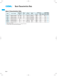
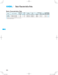
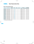
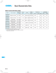
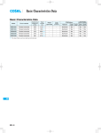
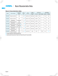
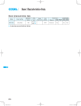
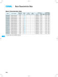
Basic Characteristics Data
Basic Characteristics Data
Model
LEP100F
LEP
LEP150F
LEP240F
Circuit method
Material
Single
sided
Series/Parallel
operation availability
Double Series Parallel
sided operation operation
Thermistor
CEM-3
Yes
Yes
*1
2.0
250V 6.3A Thermistor
CEM-3
Yes
Yes
*1
3.3
250V 10A
CEM-3
Yes
Yes
*1
Switching
Input
frequency
current
[kHz]
*2 [A]
Active filter
80
Forward converter
120
Active filter
80
Forward converter
130
Active filter
80
Forward converter
120
1.4
Rated
input fuse
Inrush
current
protection
250V 5A
SCR
PCB/Pattern
*1 Refer to Instruction Manual.
*2 The value of input current is at ACIN 100V and rated load.
LEP-8
LEP_E.indd 8
15.6.18 5:13:22 PM
AC-DC Power Supplies Open Frame/ Enclosed Type Instruction Manual
1
Function
LEP-10
1.1
Input voltage range
LEP-10
1.2
Inrush current limiting
LEP-10
1.3
Overcurrent protection
LEP-10
1.4
Peakcurrent protection
LEP-10
1.5
Overvoltage protection
LEP-10
1.6
Output voltage adjustment range
LEP-10
1.7
Isolation
LEP-10
2
Series Operation and Parallel Operation
LEP-11
3
Assembling and Installation Method
LEP-11
3.1
Installation method
LEP-11
3.2
Derating
LEP-11
3.3
Mounting screw
LEP-12
4
Ground
LEP-13
5
Peak loading
LEP-13
6
Option and others
LEP-13
6.1
Outline of option
LEP-13
6.2
Others
LEP-14
LEP-9
LEP
AC-DC Power Supplies Open Frame/ Enclosed Type
1 Function
Instruction Manual
1.4 Peakcurrent protection
nPeakcurrent protection is built-in (refer to Instruction Manual 5. for
Peak loading).
LEP
1.1 Input voltage range
If this function comes into effect, the output is shut down.
nThe range is from 85 VAC to 264 VAC or 120 VDC to 370 VDC.
The minimum interval of AC recycling for recovery is 2 to 3 min-
nIn cases that conform with safety standard, input voltage range is
utes ( ).
AC100-AC240V(50/60Hz).
nAC input voltage must have a range from 85 VAC to 264 VAC for
The recovery time varies depending on input voltage and load
condition.
normal operation. If the wrong input is applied, the unit will not operate properly and/or may be damaged.
1.5 Overvoltage protection
In addition, it is possible to correspond Low input voltage or
nOutput
Instantaneous line drop (optional : -U). Consult with us.
Working overvoltage protection.
Overvoltage protection is built-in and comes into effect at 115-
1.2 Inrush current limiting
140% of the rated voltage.
nInrush current limiting is built-in.
The AC input should be shut down if overvoltage protection is in
nIf a switch is being used for input, ensure that it is configured to
operation.
handle the input inrush current.
The minimum interval of AC recycling for recovery is 2 to 3 minutes ( ).
lLEP100F LEP150F
nThe thermistor is used for protection from inrush current. When
The recovery time varies depending on input voltage.
Remarks:
power is turned ON/OFF repeatedly within a short period of time,
Please avoid applying the over-rated voltage to the output termi-
it is necessary to have enough time for power supply to cool down.
nal. Power supply may operate incorrectly or fail.In case of operating a motor etc. , please install an external diode on the output
lLEP240F
terminal to protect the unit.
nA thyristor is used for protection from inrush current. When turning the power OFF and then ON again within a short period of
1.6 Output voltage adjustment range
time, inrush current limiting may be disabled; therefore ensure
nAdjustment of output voltage is possible by using potentiometer.
enough time before switching ON.
nOutput voltage is increased by turning potentiometer clockwise
and is decreased by turning potentiometer counterclockwise.
1.3 Overcurrent protection
nOvercurrent protection is built-in and comes into effect at over
101% of the peak current in.Overcurrent protection prevents the
1.7 Isolation
nFor a receiving inspection, such as Hi-Pot test gradually increase
unit from short circuit and overcurrent condition.
(decrease) the voltage for the start (shut down).
The unit automatically recovers when the fault condition is cleared.
Avoid using Hi-Pot tester with the timer because it may generate
voltage a few times higher than the applied voltage, at ON/OFF of
lIntermittent current characteristics
a timer.
nWhen the output voltage drops more than 50% of the rated output
If the unit is tested on the isolation between input & output and
voltage value at overcurrent, the average output current is re-
output & FG, remote ON/OFF (option) must be shorted to outputs.
duced by intermittent operation of power supply.
LEP-10
AC-DC Power Supplies Open Frame/ Enclosed Type
2 Series Operation and
Parallel Operation
nSeries operation is available by connecting the outputs of two or
more power supplies with the same output voltage, as shown below. Output current in series connection should be lower than the
lowest rated current in each unit.
Instruction Manual
3 Assembling and
Installation Method
3.1 Installation method
nWhen two or more power supplies are used side by side, position
them with proper intervals to allow enough air ventilation. Ambient
temperature around each power supply should not exceed the
temperature range shown in derating curve.
(a)
nIf using a metal chassis, ensure a gap of d1 and d2 between the
Power +
Supply -
Load
parts lead and the metal chassis for insulation. If the gap is
Power +
Supply -
smaller than d1 and d2, then ensure that insulation sheet is used
between the power supply and the chassis in order to ensure insulation.
d2
CN1
(b)
d1
Load
Power +
Supply -
Power +
Supply -
d2
Load
d1=8mm min
CN1
nParallel operation is not possible.
nRedundancy operation is available by wiring as shown below.
I1
Power
supply
d2
I3
-
+
I2
-
d2=5mm min
d2
Load
Power
supply
+
d2
3.2 Derating
nIn the hatched area the specification of Ripple, Ripple Noise is different from other area.
between the values of I1 and I2.
Please make sure that the value of I3 does not exceed the rated
current of a power supply.
I3
the rated current value
nIn case , ventilation must keep the temperature of C119 below
85 . See External View for the location of C119.
nThe operative ambient temperature is different by with/without
case cover or mounting position.
Please refer to drawings as below.
Please be careful of electric shock or earth leakage in case of
temperature measurement, because C119 is live potential.
lLEP100F
(D), (E), (F) mounting
(B), (C) mounting
(A) mounting
Load factor [%]
nEven a slight difference in output voltage can affect the balance
100
80
60
40
20
0
-10
Convection
Forced air (0.5m3/min)
0
10
20
30
40
50
Ambient temperature [ ]
60
70
LEP-11
LEP
Instruction Manual
AC-DC Power Supplies Open Frame/ Enclosed Type
lLEP100F-
-SN (requirement: Min. 90 VAC)
chassis cover). This has impaired convection; therefore usage of
Load factor [%]
100
80
60
40
20
0
-10
forced air cooling is recommended.
nWhen unit mounted except below drawings, it is required to consider ventilated environment by forced air cooling for temperature
/ load derating. For details, please consult our sales or engineering departments.
Convection
Forced air (0.5m3/min)
0
10
20
30
40
50
Ambient temperature [ ]
n(F) mounting is not possible when a case cover is used. If such
60
mounting can not be avoided, then either forced air cooling to pre-
70
vent buildup of heat, or temperature and load derating are necessary. For more details, please consult our engineering depart-
lLEP150F
(D), (E), (F) mounting
(B), (C) mounting
(A) mounting
ment.
(A)
(B)
(C)
CN1
CN1
Convection
Forced air (0.5m3/min)
0
lLEP150F-
10
20
30
40
50
Ambient temperature [ ]
60
CN1
70
Standard
Position
-SN (requirement: Min. 90 VAC)
(D)
(E)
(F)
CN1
Load factor [%]
(D), (E) mounting
(B), (C) mounting
(A) mounting
100
80
60
40
20
0
-10
CN1
CN1
Convection
Forced air (0.5m3/min)
0
10
20
30
40
50
Ambient temperature [ ]
60
70
3.3 Mounting screw
nThe mounting screw should be M3. The hatched area shows the
ensure there is no contact with surface mounted components.
nKeep isolation distance between screw and internal components
in case of option ”-S”, ”-SN” as below chart.
10
20
30
40
50
Ambient temperature [ ]
60
70
LEP-12
FG 1
CN1
-SN (requirement: Min. 90 VAC)
9mm
2
9mm
(D), (E) mounting
(B), (C) mounting
(A) mounting
100
80
60
40
20
0
-10
9mm
9mm
0
9mm
9mm
1 Recommendation to electrically connect FG to metal chassis
for reducing noise.
2 LEP150F and LEP240F only
Convection
Forced air (0.5m3/min)
0
10
20
30
40
50
Ambient temperature [ ]
9mm
Convection
Forced air (0.5m3/min)
9mm
lLEP240F-
nIf metallic fittings are used on the component side of the board,
9mm
100
80
60
40
20
0
-10
allowance of metal parts for mounting.
(D), (E), (F) mounting
(B), (C) mounting
(A) mounting
9mm
Load factor [%]
lLEP240F
Load factor [%]
LEP
Load factor [%]
(D), (E) mounting
(B), (C) mounting
(A) mounting
100
80
60
40
20
0
-10
nUse an input voltage of 90 VAC or more when using SN (with
Refer to External view for location
60
70
Instruction Manual
AC-DC Power Supplies Open Frame/ Enclosed Type
Chassis
Mounting screw
Unit
6 Option and others
8mm max
6.1 Outline of option
l-G
nOption ”-G” means leakage current is smaller than standard model
4 Ground
by reducing the value of earth capacitor at input filter circuit.
Leakage current
Conducted noise
nWhen installing the power supply with your unit, ensure that the in-
put FG terminal of CN1 or mounting hole FG is connected to safety
0.1mA max
Not available
ground of the unit.
However when applying the safety agency, connect the input FG
l-R
terminal of CN1 to safety ground of the unit.
nOption ”-R” is available for remote ON/OFF.
Output
Between RC(+) and RC(-)
Mounting
hole
FG
CN1
SW ON
(4.5 - 12.5V)
ON
SW OFF
(0 - 0.5V)
OFF
R
5 Peak loading
Vcc
External Power
Source
SW
RC(+) 1
Ri
l=20mA max
RC(-) 2
nPeak load is possible to draw as below.
Output current [A]
Connector for remote ON/OFF (Optional)
Ip
: peak current
nWhen external power source is in the range of 4.5 - 12.5V, current
limit resistance R is not required. However, when external power
Iave : average current
source exceeds 12.5V, current limit resistance R must be connected.
I0
0
t1
To calculate the current limit resistance, use the following equa-
t[sec]
t2
tion:
t1
10 [sec], Iave =
Ip t1 + I0 t2
t1 + t2
rated current,
t1
t1 + t2
0.35 (at LEP100F)
t1
t1 + t2
Duty (at LEP150F, LEP240F)
R[ ]=
Vcc - (1.1+Ri
0.005)
0.005
Where;
Vcc = External Power Source
In case of LEP150F, LEP240F, Duty is depended on
Duty [%]
Duty [%]
peak load, refer to below chart.
35%
35%
10%
10%
0
240W
288W
Peak Wattage[W]
LEP150F
0
Ri
= The internal resistance (780 )
nA wrong connection may damage the internal components of the
unit.
nRemote ON/OFF circuit (RC(+), RC(-)) is isolated from input, output and FG.
380W
430W
480W
Peak Wattage[W]
LEP240F
LEP-13
LEP
AC-DC Power Supplies Open Frame/ Enclosed Type
Instruction Manual
l-S -SN
6.2 Others
n-S indicates a type with chassis, and -SN indicates a type with
nThis power supply is the rugged PCB type. Do not drop conduc-
chassis and cover. (Refer external diagram) Refer to ”Derating
tive objects in the power supply.
nAt light load, there remains high voltage inside the power supply
Curves” in Section 3.2.
for a few minutes after power OFF.
LEP l-T
So, at maintenance, take care about electric shock.
nOption ”-T” means input and output interface are changed ”Connector” to ”Terminal block”.
FG
-V
AC (L)
+V
l-U
Specifications for support of instantaneous voltage dips (low input
voltage support).
Use condition
AC50V(DC70V)
Duty 1s/30s
Output
LEP100F
75W
LEP150F
114W
LEP240F
180W
Avoid continuous use at low input voltage for more than 1
second, as such use can lead to damage to the power supply.
l-Z
nOur ZT3 series product can be equipped as an option. Refer to
the external diagram for the output interface. Refer to the full catalog for ZT specifications. ZT can be selected from the following.
Optional symbol
Mounted Power supply
Notice
Optional symbol
Mounted Power supply
Notice
LEP-14
stress to PCB like twisting or bending causes the defect of the
unit, so handle the unit with care.
AC (N)
Input
nThis power supply is manufactured by SMD technology. The
-Z35
-Z34
-Z33
-Z32
-Z31
ZTW3 ZTW3
ZTS3
ZTS3
ZTS3
2415
2412
2415
2412
2405
Output voltage in LEP series is 24[V], 36[V].
-Z45
-Z44
-Z43
-Z42
-Z41
ZTW3 ZTW3
ZTS3
ZTS3
ZTS3
4815
4812
4815
4812
4805
Output voltage in LEP series is 48[V].