1
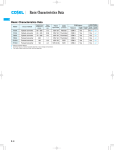
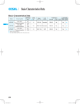
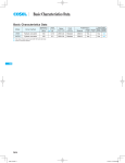
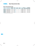
Basic Characteristics Data
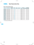
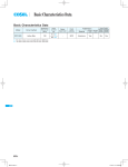
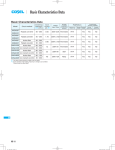
Basic Characteristics Data
UAW
Series/Parallel
operation availability
Double Series Parallel
sided operation operation
Model
Circuit method
Switching
frequency
[kHz]
Input
current
[A]
Rated
input fuse
Inrush
current
protection
Material
UAW125S
Forward converter
210
2.8
250V 5A
Thermistor
FR-4
Yes
Yes
*1
UAW250S
Forward converter
210
6.0
250V 10A
Triac
FR-4
Yes
Yes
Yes
UAW500S
Forward converter
170
12.0
250V 20A
Triac
FR-4
Yes
Yes
Yes
*1 Refer to Instruction Manual.
* The value of input current is at ACIN 100V and rated load.
UAW-8
PCB/Pattern
Single
sided
AC-DC Power Supplies Enclosed type Instruction Manual
1
Terminal Block
UAW-10
2
Function
UAW-10
3
4
2.1
Input voltage range
UAW-10
2.2
Inrush current limiting
UAW-10
2.3
Overcurrent protection
UAW-10
2.4
Overvoltage protection
UAW-11
2.5
Output voltage adjustment range
UAW-11
2.6
Remote ON/OFF
UAW-11
2.7
Remote sensing
UAW-11
2.8
Isolation
UAW-11
2.9
Thermal protection
UAW-12
Series Operation and Parallel Operation
UAW-12
3.1
Series operation
UAW-12
3.2
Parallel operation/Master-slave operation
UAW-12
Assembling and Installation Method
UAW-13
4.1
Installation method
UAW-13
4.2
Derating
UAW-13
4.3
Mounting screw
UAW-14
4.4
Others
UAW-14
UAW-9
UAW
AC-DC Power Supplies Enclosed type
1 Terminal Block
Instruction Manual
2 Function
lUAW125S
2.1 Input voltage range
nThe range is from AC85V to AC132V/AC170V to AC264V which
UAW
is automatically selected internally. But after the input voltage is
applied, avoid changing AC100V/AC200V.
nAC input voltage must have a range from AC85V to AC132V/AC170V
AC(N)
AC(L)
Frame ground
-Output
to AC264V for normal operation. If the wrong input is applied, the
+Output
Output voltage adjustable potentiometer
LED
unit will not operate properly and/or may be damaged.
nIn cases that conform with safety standard, input voltage range is
AC100-AC120V, AC200-AC240V(50/60Hz).
lUAW250S
2.2 Inrush current limiting
nInrush current limiting is built-in.
nIf a switch on the input side is installed, it has to be the one han-
dling the input inrush current.
AC(N)
AC(L)
Frame ground
-Output
+Output
Output voltage adjustable potentiometer
LED
lUAW125S
nThe thermistor is used for protection from inrush current. When
power is turned ON/OFF repeatedly within a short period of time, it
is necessary to have enough time for power supply to cool down.
lUAW500S
< Connector >
lUAW250S UAW500S
nThe thyristor technique is used for protection from inrush current.
When power is turned ON/OFF repeatedly within a short period of
time, it is necessary to have enough time between power ON and
OFF to operate resistance circuit for inrush current.
AC(L)
AC(N)
NC
Frame ground
+Output
-Output
Connector
LED
Output voltage adjustable potentiometer
< Connector >
Pin No.
Function
Connection is not possible.
Connection is not possible.
Connection is not possible.
Self sensing terminal.(Do not wire for external connection.)(-M)
-Remote sensing(-S )
Self sensing terminal.(Do not wire for external connection.)(+M)
Connection is not possible.
+Remote sensing(+S )
Voltage balance(VB)
Current balance(CB)
2.3 Overcurrent protection
nOvercurrent protection is built-in and comes into effect at over
105% of the rated current. Overcurrent protection prevents the
unit from short circuit and overcurrent condition. The unit automatically recovers when the fault condition is cleared.
nIf the output voltage drops more than 50% of the rated voltage in
an overcurrent protection mode, the average current will also be
reduced by the intermittent operation.
UAW-10
Instruction Manual
AC-DC Power Supplies Enclosed type
2.4 Overvoltage protection
2.7 Remote sensing
nThe overvoltage protection circuit is built-in and comes into effect
(1)When not using remote sensing function
at 115 - 140% of the rated voltage (except 3V output voltage type:
it operates at 4.00 - 5.25V). The AC input should be shut down if
overvoltage protection is in operation. The minimum interval of
UAW
AC recycling for recovery is 5 minutes.
The recovery time varies depending on input voltage.
(2)When using remote sensing function
Remarks:
Please avoid applying the over-rated voltage to the output termi-
Use twisted - pair wire or shielded-wire
nal. Power supply may operate incorrectly or fail.In case of operating a motor etc. , please install an external diode on the output
terminal to protect the unit.
R1
C1
+
+
C2
2.5 Output voltage adjustment range
nAdjustment of output voltage is possible by using potentiometer.
-M
-S
+M
+S
-
+
+
C3
Attention to
connection
(+)
Load
(-)
Attention to
connection
nOutput voltage is increased by turning potentiometer clockwise
and is decreased by turning potentiometer counterclockwise.
nWhen not using this function, confirm that terminals are shorted
between +S and +M, and between -S and -M with short pieces.
nWhen using this function, wiring should be done without short
2.6 Remote ON/OFF
pieces.
lUAW250S (optional ”-R”)
nDevices inside the power supply might be damaged when poor
nOption ”-R” is available for remote ON/OFF.
Between RC and RCG
Output
SW ON
(High)
ON
SW OFF
(0 - 0.5V)
OFF
connection on load lines occurs, e.g. because of loose connector
screws.
nThick wire should be used for wiring between power supply and
load, and line voltage drop should be less than 0.3V.
nWhen long sensing wire is required, use C1, C2 and C3.
nTwisted-pair wire or shield wire should be used for sensing wire.
nPlease do not draw output current from +M, -M terminal.
1 To calculate the current limit resistance use following equation:
R[ ]=
nWhen remote sensing function is used, output voltage might be-
Vcc-1.1
come unstable because of a impedance of wiring and load condi-
0.005
tion. And the power supply should be evaluated enough.
where: Vcc = External power source
Following are examples to improve it.
-S sensing wire is removed and terminals between -M and -S
are shorted.
C3 and R1 are connected as above figure.
2.8 Isolation
nFor a receiving inspection, such as Hi-Pot test, gradually increase
(decrease) the voltage for the start (shut down). Avoid using Hi1 Current limit resistance: R(Recommendation)
External Power Source
R
750
5V
12V
2.2k
24V
4.7k
Pot tester with the timer because it may generate voltage a few
times higher than the applied voltage, at ON/OFF of a timer.
nIf the unit is tested on the isolation between input & output and
output & FG, remote ON/OFF must be shorted to output.
nA wrong connection may damage the internal components of the unit.
nRemote ON/OFF circuit (RC, RCG) is isolated from input, output
and FG.
UAW-11
AC-DC Power Supplies Enclosed type
2.9 Thermal protection
lUAW250S UAW500S
lUAW250S UAW500S
nParallel operation is available by connecting the units as shown
nThermal protection is built-in. If this function comes into effect,
shut down the output, eliminate all possible causes of overheating, and drop the temperature to normal level. Output voltage recovers after applying input voltage. To prevent the unit from overheating, avoid using the unit in a dusty, poorly ventilated environment.
below.
nAs variance of output current drew from each power supply is
maximum 10%, the total output current must not exceed the
value determined by the following equation.
(Output current at parallel operation)
= (the rated current per unit)
(number of unit )
0.9
When the number of units in parallel operation increases, input
3 Series Operation and
Parallel Operation
current increases at the same time. Adequate wiring design for input circuitry is required, such as circuit pattern, wiring and current
capacity for equipment.
In parallel operation, the maximum operation number of units is 5.
3.1 Series operation
nSeries operation is available by connecting the outputs of two or
nOutput voltage in parallel operation is adjustable by using the po-
more power supplies, as shown below. Output current in series con-
tentiometer of the ”master” unit. Select one power supply to be
nection should be lower than the lowest rated current in each unit.
the master, and turn the potentiometer of the other, ”slave” power
supplies, clockwise to the end. Then use the potentiometer of the
(a)
(b)
master to adjust output voltage.
nWhen remote sensing is used in parallel operation, the sensing
wire must be connected ONLY to the master. Terminals between
+S & +M and -S & -M of ”slave” power supplies must be shorted.
3.2 Parallel operation/master-slave operation
lUAW125S
nIn parallel operation, output voltage increases like stairs due to a
nParallel operation is not possible.
nRedundancy operation is available by wiring as shown below.
Power
supply
+
I1
I3
-
Load
UAW
Instruction Manual
Power
supply
+
I2
-
nEven a slight difference in output voltage can affect the balance
between the values of I1 and I2.
Please make sure that the value of I3 does not exceed the rated
current of a power supply.
I3
UAW-12
the rated current value
delay of the rise time of output voltage at turn on.
AC-DC Power Supplies Enclosed type
nIn parallel operation, please connect diode to the + side of the out-
put circuit. If diode is connected to the-side, it will damage the
unit or/and the balancing function will not work.
Instruction Manual
4.2 Derating
nThe operative ambient temperature is different by with/without
case cover or mounting position. Please refer drawings as below.
nWhen unit mounted except below drawings, it is required to con-
sider ventilated environment by forced air cooling for temperature/load derating. For details, please consult our sales or engineering departments.
lUAW125S
<Convection>
YES
NO
4 Assembling and
Installation Method
4.1 Installation method
nWhen two or more power supplies are used side by side, position
them with proper intervals to allow enough air ventilation. Ambient
<Forced air>
temperature around each power supply should not exceed the
temperature range shown in derating curve.
nFan for forced cooling is optional. Do not block the ventilation at suc-
tion side (terminal block side), its opposite side and upper side.
nWhen unit operates at dusty place, attach air-filter to avoid dust
into the unit. In this case, avoid poorly ventilated environments.
Operation by forced air cooling is possible except A, B mounting.
Please operate below 80
of the unit at part A.
Note:
In the hatched area, the specification of Ripple, Ripple Noise is
different from other area and the input voltage should be used
more than AC90V.
UAW-13
UAW
Instruction Manual
AC-DC Power Supplies Enclosed type
lUAW250S
nWhen fan is set separately, the temperature of part A of the unit
should be below 75 degree by flowing cooling-air inside of the
unit.
130
37
UAW
A
FAN
Keep the temperature of part A and B as below.
: below 90
part B (C13)
: below 85
AIR
Load factor [%]
part A (chassis of power supply)
4.3 Mounting screw
nKeep isolation distance between screw and internal components
as below.
Without
case cover
25
With case cover
35
45
55
65
Ambient temperature [ ]
Note:
In the hatched area, the specification of Ripple, Ripple Noise is
different from other area.
4.4 Others
nFan unit (Optional)
The power supply is designed to operate with the fan (forced air cooling). The optional external fan unit is listed in the following table.
lUAW500S
No
Model
Model with fan unit
Fan unit
UAW500S- 3
UAW500S- 5
UAW500S-12
UAW500S-24
UAW500S- 5-F
UAW500S-12-F
UAW500S-24-F
F500- 5
F500-12
F500-24
In case of unit with fan, the efficiency is lower 1% typ by power
dissipation of fan.
The lifetime of fan varies depending on operating condition, so
Expected life time
please replace the fan regularly.
Note:
In the hatched area, the specification of Ripple, Ripple Noise is
different from other area .
UAW-14
103H
40
30
0
50 60
Operating ambient
temperature