1
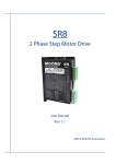
Packaged Stepper Motor System
Sim-Step
A complete system solution
Plug & run simplicity
Programmable positioning
Optional closed loop control
Matching size 17 – 34 frame motors
Motor torque ratings up to 1.5 Nm
Optional planetary gearheads
Geared motor options up to 100Nm
Sim-Step
Mclennan Servo Supplies Ltd. Tel: +44 (0)8707 700 700 www.mclennan.co.uk
4526-f
Page 1/16
Packaged Stepper Motor System
Sim-Step
The Sim-Step integrated stepper motor controller provides
a cost effective solution to a wide range of applications
that require accurate manipulation of the driven
mechanism.
The unit is ‘plug & run’ package that greatly reduces
installation time. Simply connect the intelligent drive to a
PC, motor, travel limits etc & an ac supply using cables
provided and the system is fully operational.
Features:
•
•
•
•
•
•
•
•
•
•
•
•
•
•
•
Integrated Power supply for direct connection to AC Supply
Choice of 115 or 230 Vac, 50 or 60Hz operation
Integrated high efficiency Bi-polar drive stage
400 step/rev. motor resolution provides increased smoothness
Internally adjustable phase current from 0.5-3.5 Amps
Integrated motion controller
RS232 or RS485 communication
Up to 99 units can be daisy chained to a single port
Internal memory stores sequences for stand-line operation
Programmable position, acceleration, deceleration & velocity
8 input & 8 output Digital I/O to interface with other process functions
Optional jog box for manual operation
Choice of matched size 17, 23 & 34 frame motors
All connections by plug & socket for ‘Plug & Run operation’
Modular construction for improved serviceability
Dimensions: mm
Encoder
Limits
I/O signals
A B
Motor
Diagnostics display
Power switch
Fuses
128
in out
RS 232
293
AC Supply
Jog
(Not including handle or connectors)
Rack mounting installation ( front )
Installation
Up to 3 units may be installed in a
single 3U high rack installation or
alternatively the drive may be base
mounted using the mounting bracket
as shown:
Part #’s
506RAC10001 = Simrack 1
506RAC00002 = Simrack 2
506RAC00003 = Simrack 3
142
133
Base mounting ( front )
`
150
483 (19 in )
80
Rear
Mclennan Servo Supplies Ltd. Tel: +44 (0)8707 700 700 www.mclennan.co.uk
Mounting using base bracket
4526-f
Page 2/16
Specification
Sim-Step
Supply
Vac
Motor Drive type
Phase current
Amps
Motor Drive rail
Vdc
Protection
Motion control communication
Number of axes
Internal communication set-up options
Programmable Motion control
functions
Motion control parameters:
115 or 230 50 or 60Hz ( internally selectable )
2 phase Bi-polar, high efficiency chopped constant current
Internally adjustable 0.5 to 3.5 per phase
40
Short circuit, over-temperature
RS232 or RS485:
Up to 99 units may be connected to single communication port
Baud rate & axis address code ( up to 99 )
Open loop or closed loop using scaled encoder feedback
2
Max. acceleration rate
Steps/sec
2
Max. deceleration rate Steps/sec
Max. velocity
Steps/sec
Max move length
Steps
Max creep speed
Steps/sec
Sequences & programmable I/O
Number of pre-programmed
sequences
Number of commands per sequence
Number of user programmable inputs
Number of user programmable outputs
Limits datum & registration inputs
End of travel limit protection
Limit activation
Datum search
Registration
Abort stop input
Acceleration, deceleration, velocity, relative & absolute moves,
creep distance & speed, sequences & I/O states
500,000
500,000
1,200,000 (20,000 Typical with 23HS Motor)
2,000 million
800 (max recommended start / stop rate)
8 stored in non-volatile memory for off-line operation
127
8 Optically isolated digital inputs
8 Optically isolated digital outputs
Direction sensitive via normally closed direction limits
or optional software limits avoid programming errors
Programmable choice of Hard Limit Stop ramp. Independently
programmable deceleration on Limit activation
Via approach signal input & datum stop signal ( normally-open )
Or single datum switch or encoder index using high-speed capture
High speed datum registration up to 1,200,000 steps/sec.
Normally closed signal aborts move.
Typical programmable velocity profile
Programmable positioning features
sv
Set velocity
Set deceleration
Set acceleration
sd
sa
Target
Position
Set creep
speed
mr
Relative move distance
ma
Absolute move position
cr creep distance
sc
time
time
Alternative Over-travel Limit operation
Reliable stopping
@ slow speed
Ramped limits give reliable
position memory for high speed
stopping
Overshoot
detected
High speed datum registration
Datum acquisition with
auto ramp & return
Auto return
Mclennan Servo Supplies Ltd. Tel: +44 (0)8707 700 700 www.mclennan.co.uk
Datum always approached
in same direction
Auto return
4526-f
Page 3/16
Packaged Stepper Motor System
Sim-Step
Up to 99 drives may be controlled from single comms port
The Sim-Step unit may be internally pre-set during commissioning with a unique axis address code so that up
to 99 units may be addressed from a single comms port.
Absolute positioning using ‘ma’ command
The use of the ‘ma’ command enables the absolute
position of a driven mechanism to be programmed
Eg:
1ma6000
1ma4000
1ma0
0
2000
4000
6000
0
2000
4000
6000
Relative moves using ‘mr’ command
The use of the ‘mr’ command controls the move
distance relative to the last position
Eg:
1mr6000
1mr-2000
1mr-4000
Using digital I/O in sequences
Digital I/O ports may be programmed by the user and
incorporated in pre-programmed sequences to
interface with other machine functions when using the
controller in stand-alone applications.
used as
Eg:
1ds1
( define sequence 1 )
1wa00000001 ( wait for ‘1’ signal on input
port 1 to start sequence)
1ma6000
( move instruction )
1we
( wait for end of move )
1wp00000001 ( write ‘1’ signal on output
port 1 )
1wa00000010 ( wait for ‘1’ signal on input
port 2 )
1ma4000
( move instruction )
1we
( wait for end of move )
1wp00000010 ( write ‘1’ signal on output
port 2 )
1wa00000100 ( wait for ‘1’ signal on input
port 3 )
1ma0
1we
( wait for end of move )
1wp00000100 ( write ‘1’ signal on output
port 3 )
1de1000
( dwell for 1 second )
1we
( wait for end of delay )
1wp00000000 ( reset output ports )
1es
end sequence
Input signals
Output signals
0
2000
4000
6000
By sending command: 1xs1 ( execute sequence one ) the above motion programme is executed once. By
adding a 1xs1 command at the end of a sequence before the 1es command, the sequence can be made to
continuously repeat.
Mclennan Servo Supplies Ltd. Tel: +44 (0)8707 700 700 www.mclennan.co.uk
4526-f
Page 4/16
Packaged Stepper Motor System:
Programming Guide
The control systems utilise a powerful motion controller per axis
that provide accurate motion control and integration with other
machine functions. The system may be programmed via an RS232
interface to provide motion in real time on receipt of a movement
command.
Alternatively a series of sequences can be programmed to enable
the unit to operate as a stand-alone system, interfaced to other
machine functions.
Commands are shown below:
Table of commands
GETTING STARTED COMMANDS
HE
HP
QS
HElp pages
Display Previous Page
Query Speeds
HN
IN
QA
Display Next Page
INitialise
Query All
ABORT, STOP & RESET COMMANDS
CONTROL C
AM<mode>
RS
ST
Hard Stop
Set Abort Mode
ReSet
Soft Stop
ESC
AB
QM
Soft Stop
Command ABort
Query Mode
INFORMATION
CO
OC
OD
OS
QA
QS
QM
Display the Current Operation
Output Command position
Output Datum position
Output Status string
Query All
Query Speeds
Query Modes
ID
OA
OV
OF
IDentify Version
Output Actual position (Encoder 1)
Output Velocity
Output Following Error
QP
QL
Query Positions
Query Privelge Level
SET UP
CM<mode>
BO<steps>
TO<value (ms)>
WI<steps>
Set Control Mode
Set Back Off Steps
Set Time Out
Set settling Window
ER<numerator>/<denominator>
CR<steps>
SE<time (ms)>
Set Encoder Ratio
Set CReep steps
Set SEttling time
TO<value ms>
Set Time Out time
FAULT DETECTION FEATURES
SL<mode>
TR<value>
Set Soft Limits
Set TRacking window
DATUMING
CD
HD<direction>
SH<position>
QM
Clear Captured Datum Position
Go Home to Datum
Set Home Position
Query Modes
OD
MD
DM<mode>
Output Datum position
Move to Datum Position
Set Datum Mode
CP<value>
Set Command Position
POSITION COMMANDS
AP<position>
DA<position>
Set Actual Position
Difference Actual position
SPEED, ACCELERATION AND DECELERATION
CV<velocity>
SF<speed>
SV<speed>
SD<deceleration>
Constant Velocity mode
Set Fast jog speed
Set Velocity
Set Deceleration
SC<speed>
SJ<speed>
SA<acceleration>
LD<deceleration>
Mclennan Servo Supplies Ltd. Tel: +44 (0)8707 700 700 www.mclennan.co.uk
Set Creep speed
Set slow Jog speed
Set Acceleration
Set Limit Deceleration
4526-f
Page 5/16
MOVES
BO<steps>
MA<position>
MD
DE<time>
Set BackOff Steps
Move Absolute
Move to Datum Position
Set DElay time
CR<steps>
MR<position>
HD<direction>
Set Creep steps
Move Relative
Go Home to Datum
UL<position>
Set Upper soft Limit
SOFT LIMITS
LL<position>
SL<mode>
Set Lower soft Limit
Set Soft Limits
END OF MOVE
SE<steps>
WE
Set SEttling time
Wait for End of current move
WI<steps>
BO<steps>
Set end of move Window
Number of Back-Off steps
WP<bit pattern>
IF<bit pattern>
Write Port
Do next command If False
READ & WRITE PORTS
RP
WA<bit pattern>
IT<bit pattern>
Read Port
WAit for input event
Do next command If True
JOG / JOYSTICK
JM<mode>
SF<speed>
JR<value>
JT<value>
Set Jog Mode
Set Fast jog speed
Set Joystick Range
Set Joystick Threshold
SJ<speed>
JC<value>
JS<speed>
QJ
Set slow Jog speed
Set Joystick Centre Position
Set Joystick Speed
Query Joystick Settings
SEQUENCES
AE<sequence no.>
DS<sequence no.>
LS<sequence no.>
BS
Auto-Execute sequence
Define Sequence
List Sequence
Backup Sequences
AD
ES
XS<sequence no.>
US<sequence no.>
Auto-Execute Disable
End Sequence definition
EXecute Sequence
Undefine Sequence
HELP
HE
HP
HS
Display HElp Pages
Display Previous Page
Help with Status output message
HN
HM
HC
Display Next Page
Help with Modes Commands
Help with Control Modes
New Pin
Set Privilege Level
PI
QL
Enter PIN
Query Privilege Level
Backup All
Backup Digiloop parameters
BS
Backup Sequences
PRIVILEGE LEVEL
NP<new PIN>
PL
BACKUP
BA
BD
Refer to the Sim-Step and PM600 manuals for further details, these can be downloaded from this link www.mclennan.co.uk/technicalmanuals.html.
Sim-Step user manual
PM600 manual
- “SimStep Single Axis Stepper Drive Manual”
- “PM600 - Motion Controller Manual”
Mclennan Servo Supplies Ltd. Tel: +44 (0)8707 700 700 www.mclennan.co.uk
4526-f
Page 6/16
Packaged System
HS series motor options with leads:
HS series motor features:
•
•
•
•
•
•
•
Choice of 3 frame sizes
High quality hybrid construction
400 step / rev resolution using packaged drive
Optimised for high speed performance
Options with encoders for closed loop control
Choice of gearhead options for increased torque & resolution
Matched cable and connector box for simplified connections
Size 17 motors:
17HS series
Two models provide a choice of body lengths & performance
17HS series
Dimensions: mm
11
42
20
Torque ( Ncm )
L
∅ 22
2
∅ 5
Rear shaft
17HS-020E: L: 34 mm
17HS-240E: L: 46 mm
2 studs
M3 x 5.5 long
31
16
14
12
10
8
6
17HS-020
4
2
0
17HS-240
0
2000 4000 6000 8000 10000 12000
half steps per sec. ( 0.9 degrees )
High speed size 23 motors
23HS series
23HS Mk 2 Series
Two models provide a choice of body lengths & performance
40
optional
rear shaft
1.6
35
∅ 5.2
320 typical
Torque ( Ncm )
4.8
+0
23 HS
Series
∅ 6.35 -0.013
dimension L
23HS-108: L : 52 mm
23HS-309: L: 67 mm
20
23HS-108
15
23HS-309
10
0
47.2
20.6
25
5
∅ 38.1+0.025
19
30
0
57.2
5000
34HS-109
86
2 max
100
83
+0
9.525 -0.013
34 HS 109
69.6
Torque ( Ncm )
5
optional
rear shaft
80
60
40
20
0
5.5
0
28.6
62.3
20000
34HS series
Dimensions: mm
typical
15000
half steps/sec. ( 0.9 degrees )
High speed size 34 motors
300
10000
30.2
10000
15000
20000
half steps per sec ( 0.9 degrees )
73.02
Mclennan Servo Supplies Ltd. Tel: +44 (0)8707 700 700 www.mclennan.co.uk
5000
4526-f
Page 7/16
Packaged System
HSX series motor options with leads:
HSX series motor features:
•
•
•
•
•
•
•
Choice of 2 frame sizes
Hybrid construction featuring high energy magnets
400 step / rev resolution using packaged drive
Optimised for high torque output
Options with encoders for closed loop control
Choice of gearhead options for increased torque & resolution
Matched cable and connector box for simplified connections
High torque size 23 motors
23HS series
23HSX Series
5.0
optional
rear shaft
1.6
∅ 5.0
300 typical
Torque ( Ncm )
+0
∅ Ds
-0.013
∅ 38.1+0.05
19
47.2
dimension L
20.6
Dimension: L
23HSX-206: 55 mm
23HSX-306: 78.5 mm
57.2
∅ Ds
6.35
8.0
100
90
80
70
60
50
40
30
20
10
0
23HSX-206
23HSX-306
0
2000
4000
6000
8000
10000
half steps per sec. ( 0.9 degrees )
High torque size 34 motors
34HSX series
34HSX Series
86
400
typical
8
250
∅ 5.6
1.6 max
optional
rear shaft
+0
∅ 9.525 -0.013
34 HSX
69.6
Series
Torque ( Ncm )
8.4
20
28.5
dimension L
30.2
∅ 73.02
200
34HSX-108
34HSX-208
150
100
50
0
0
Dimension L: 34HSX-108: 67 mm
34HSX-208:: 94 mm
1000 2000 3000 4000 5000 6000
half steps per sec. ( 0.9 degrees )
Ensure the drive current is set appropriately for the rating of the motor.
Standard configuration is set at 3.5 Amps.
Refer to section 6 of the Sim-Step user manual which can be downloaded from www.mclennan.co.uk/technicalmanuals.html - “SimStep Single Axis Stepper Drive Manual”
Mclennan Servo Supplies Ltd. Tel: +44 (0)8707 700 700 www.mclennan.co.uk
4526-f
Page 8/16
Packaged system
HSX series motors with encoders:
When specifying a stepper motor with encoder add the part number of the encoder to that of the motor
Eg:
Stepper motor – encoder
23HSX-206 - CI 500L
23HSX-306 - CI 500L
34HSX-108 - RI 500L
34HSX-208 - RI 500L
Dimensions: mm
Stepper motor
Fitted with
CI Encoder
motor rear
face
460
ribbon cable on
CI...L encoder
or
RI..L Encoder
30
26.3
23 HSX
14.9
motor
18.3
23.3
55
34 HSX
motor
0.5
31
DIMENSIONS: mm.
RI..L Encoder
Motors with connectors & optional encoders:
Model 23HT
Model 34HT
Mclennan Servo Supplies Ltd. Tel: +44 (0)8707 700 700 www.mclennan.co.uk
4526-f
Page 9/16
Packaged System Accessories:
Sim-Step
Motor, datum & limit cables
Motor & datum / limit cables fitted with connectors to plug into the
rear panel of the controller may be specified with alternative lengths:
Note: Alternative cable lengths up to 30m may be specified to special order.
Datum Limit Cable options
Length
1m
2m
3m
5m
10m
type
507LDC01894
507LDC02894
507LDC03894
507LDC05894
507LDC10894
Datum / limit cables
Junction Box type
Type MSA889
Motor cable
Motor cable options
- Limit
Datum
Length
1m
2m
3m
5m
10m
+ Limit
Motor
type
507MOC01892
507MOC02892
507MOC03892
507MOC05892
507MOC10892
Note: Limit switches must be “normally closed” type.
Junction box
Motor cable
Sim-Step controller
The motor cable is provided with a connector
that either plugs into the junction box or a motor
equipped with a connector
HSX motor with leads
Plug & run simplicity
OR
Note: For connections to “HT” type motor, the winding configuration is set by the cable
Parallel = 507MOCxx922
Series = 507MOCxx944
Where xx is the cable length in meters
Mclennan Servo Supplies Ltd. Tel: +44 (0)8707 700 700 www.mclennan.co.uk
4526-f
Page 10/16
Packaged System Accessories:
Sim-Step
Connecting motors to the junction box
MSA 889
Depending on the motor selected it will have either 4 or 8 leads which can be identified as shown below
4 lead 17HS series motor
White
1
8 lead 23 & 34 frame size motors
Red
1
1’
3’ 3
2
2’
4’
2
Yellow Blue
4
Colour Code for 8 lead motors:
Motor
HS Series
Lead identification
1
1’
Red
White/Red
2’
White/Yellow
2
Yellow
3
Black
3’
White/Black
4’
White/Orange
4
Orange
23HSX
Red
White/Red
White/Yellow
Yellow
Orange
White/Orange
White/Brown
Brown
34HSX
Red
White/Red
White/Yellow
Yellow
Black
White/Black
White/Orange
Orange
The motor is connected into the junction box as shown below:
Motor Lead connections
57 mm
4 Lead motors
1’
Link for parallel
Operation
1
1’
2’
2
3
3’
4’
4
126 mm
8 Lead motors
Motor Lead
507 MOC series
Motor leads
1
1’
2’
2
3
3’
4’
4
HS & 34 HSX
23HSX
Junction Box MSA889
Mclennan Servo Supplies Ltd. Tel: +44 (0)8707 700 700 www.mclennan.co.uk
4526-f
Page 11/16
Packaged System Accessories:
Sim-Step
Connecting motors to the junction box
MSA 889
Limit / datum connections
0VLL
+VLL
Upper Limit
+VLL
Lower Limit
+VLL
Datum App
+VLL
Datum stop
+VLL
Abort stop
Limits datum cable
507 LDC series
1’
+over-travel limit
- over-travel limit
datum approach *
datum stop
abort stop **
Allow sufficient deceleration over-travel
deceleration
deceleration
zone
working zone
zone
- Limit
+ Limit
Notes on connection of datum & limits terminals.
General:
All limit and datum signal inputs should utilise normally closed contacts.
Note*
a)
b)
Note **
The datum approach signal is not always required. This is the case when:
The motor is operated at slow ( creep speed ) since it is not necessary to decelerate before
stopping at the datum point. In this case the datum approach terminals should not be
connected.
When the controller is configured to utilise the high speed datum registration feature. In this
case the datum approach connections should be linked.
This connection enables an external open contact to abort a move. However for this feature to
be utilised it is necessary to remove an internal link LK8 within the controller.
Using Over-travel limits as datum inputs.
0VLL
+VLL
Upper Limit
+VLL
Lower Limit
+VLL
Datum Approach
+VLL
Datum Stop
+VLL
Abort stop
In applications where space is limited the end of travel limit
switches may also be used as the datum stop switch. In the
example shown the lower limit switch is also connected to the
datum stop input and the controller is configured to utilise the high
speed datum approach facility.
It should be noted that the end of travel limit switches should be
placed sufficiently within the total travel area to allow the motor to
decelerate from high speed.
Mclennan Servo Supplies Ltd. Tel: +44 (0)8707 700 700 www.mclennan.co.uk
4526-f
Page 12/16
Packaged System Accessories:
Sim-Step
Manual Jog Boxes
JC Series
JC Series Jog boxes provide a convenient way to manually control motor control systems which are equipped Sim-Step.
Three models are available which provide the following manual control functions:
•
•
•
Bi-directional single step ( jog) function by momentary depression of ‘+’ or ‘-’ buttons.
Slow speed continuous operation in desired direction by the depression & holding of the ‘+’ or ‘-’ buttons. Programmable
during commissioning to meet the user’s exact requirements. (programmed in the controller using ‘sj’ command)
Fast speed, continuous operation in desired direction by depressing & holding the ‘F’ button together with either the ‘+ or
‘- button. The fast positioning rates are programmable during commissioning to meet the user’s exact requirements.
(programmed in the controller using ‘sf’ command).
Single axis installations
Sim-Step
For single axis drives
specify JC100 Jog box
and connect it to the
green ‘D’ connector on
the Sim-Step as shown
SINGLE
AXIS
JOG BOX
JC100
JC100
Dual axis installations
For dual axis drives specify JC200 Jog box
and connect it to the green ‘D’ connector on
the Sim-Step as shown
A
DUAL
AXIS
JOG
JC200
JC200
Use jog link cable
Note: Jog link cable is handed, identified by the
colour of the screw heads as shown
1
2
3-15 axis installations
For 3-15 axes drives specify JC809 Jog box
and connect it to the green ‘D’ connector on
the Sim-Step as shown
JC809
Fit terminator
Supplied with
JC809
Use jog link cables 507JDC05021
Mclennan Servo Supplies Ltd. Tel: +44 (0)8707 700 700 www.mclennan.co.uk
4526-f
Page 13/16
Packaged System Accessories:
Sim-Step
Encoder cables
507ENC Series
The Sim-Step control module module may be connected to the encoder
via an encoder cable that is equipped with connectors at each end.
One connector plugs into the controller, the other into
the motor encoder extension cable as shown.
Alternatively, the cable is plugged directly into the motor’s
connector box when a motor of this type is specified.
Encoder cables
- Limit
Datum
+ Limit
Order Code
Cable length
507ENC01893
507ENC02893
507ENC03893
507ENC05893
507ENC10893
1m
2m
3m
5m
10 m
Motor-encoder
Note : Specify connector on encoder
Lead motors equipped with encoders
The following stepper motors are equipped with leads for connection to the MSA889 junction box & encoders
equipped with connectors for direct connection to the Sim-Step controller via a 507ENC cable. The use of the
MSA889 junction box also provides a convenient way of terminating limits & datum signals as previously
described.
Motor encoder options:
Frame size
Motor encoder
Order Code
Size 17
17HS-240 CI 500L
301HSE00052
Size 23
23HSX-206 CI 500L
23HSX-306 CI 500L
301HSE00053
301HSE00054
Size 34
34HSX-108 RI 500L
34HSX-208 RI 500L
301HSE00055
301HSE00056
Mclennan Servo Supplies Ltd. Tel: +44 (0)8707 700 700 www.mclennan.co.uk
4526-f
Page 14/16
Packaged System Accessories:
Sim-Step
I/O cable and Break-out box
.
An I/O cable complete with ‘break-out’ DIN rail mounting terminal box may be specified.
85 mm
70 mm
The I/O break-out box features screw
terminals to enable the 16 Digital I/O to
be easily connected.
-Limit
Datum
The unit is DIN rail mounted so that it can be
Sited next to a typical PLC
control unit
+ Limit
Motor
I/O Break-out box ordering details
I / O break-out box: 506MSC00891
1 m I/O cable
507IOC01895
I / O Break-out box 506MSC00891 Connections:
Output Lines
WP1
WP2
WP3
WP4
WP5
WP6
WP7
WP8
WP com
Diode-com
+VLL
0V
Input Lines
RP1
RP2
RP3
RP4
RP5
RP6
RP7
RP8
RP-com
N/C
+VLL
0V
Typical Output Line
Connections
Typical Input Line
connections
WP
RP
Low current Relay
WP – com
Diode com
+VLL
0V
Mclennan Servo Supplies Ltd. Tel: +44 (0)8707 700 700 www.mclennan.co.uk
RP-com
+VLL
0V
4526-f
Page 15/16
HPE Series Low backlash gearheads for Sim-Step system
HPE series gearheads provide a combination of reduced backlash and economic
prices. They are specifically designed for applications that require long life, high
dynamic repetitive cycle operation and high positional accuracy.
Dimensions: mm
Gearhead
Version
Gearbox Diameter
Output shaft diameter
Gearbox mounting register
Gearbox mounting holes
mounting hole PCD
Shaft fixing bolt diameter
Gearbox Length
Overall Output Shaft length
Gearbox register length
Free shaft length
Adaptor length
Output shaft key width
Output shaft Key length
Key distance to shaft end
Shaft fixing tapped length
Motor adaptor size
Suitable stepper motors
HPE50
HPE50-S
50
12 k6
35 h6
4 x M4
44
tapped
53
24.5
4
18
D1
D2
D3
d4
D4
D5
L1
L2
L3
L4
L5
L6
L7
L8
L9
L10
HPE50-D
50
12 k6
35 h6
8 deep
44
M4
74.5
24.5
4
18
HPE70
HPE70-S
70
16 k6
52 h6
4 x M5
62
tapped
69
36
5
28
4 h9
14
2
8
57.2
23HS (X)
5 h9
25
2
10
83
34HS (X)
18
4 h9
14
2
8
57.2
23HS (X)
∅ D1
22
5 h9
25
2
10
83
34HS (X)
L10
L6
L3
L7
L8
D4
HPE series
GEARHEAD
HS series
stepper motor
HPE90
HPE90-S
90
22 k6
68 h6
4 x M812 deep
80
tapped M8
109
46
5
36
30
6 h9
32
2
13
90
34HS (X)
HPE70-D
70
16 k6
52 h6
10 deep
62
M5
91.5
36
5
28
D5
∅D2
d4
L9
L4
L5
L1
∅ D3
L2
Performance:
Model
Gear Ratio
Options:
n:1
HPE 50-S
5
10
25
50
100
5
10
25
50
100
25
50
100
HPE50-D
HPE 70-S
HPE 70-D
HPE 90-D
Max.
Backlash
( arc. min.)
< 12
Typical
Input
Friction
( Nm )
0.05
Typical
Efficiency
(%)
> 97
< 15
0.04
> 95
< 12
0.14
> 97
< 15
0.12
> 95
< 15
0.51
> 95
Maximum
Continuous
Torque
( Nm )
6.5
5.5
6.5
6.5
5.5
18
16.5
18
18
16.5
45
45
40
Max.
Peak
Torque
( Nm )
15
12
15
15
12
33
30
33
33
30
82
82
72
Maximum
Emergency
Torque
( Nm )
28
Mass
( Kg )
0.8
28
1.0
75
2.0
75
2.5
200
5.3
General specification
Model
HPE 50
HPE 70
HPE 90
Max Radial
Load
(N)
850
1650
2600
Max. Axial
Load
(N)
700
1600
2000
Torsional
Rigidity
( Nm/Arc min.)
1
2
6
Max. input
speed
( rpm )
8,000
6,000
6,000
Lubrication
Paint Finish
Stoved epoxy
gloss
grease
grease
grease
Mclennan Servo Supplies Ltd. Tel: +44 (0)8707 700 700 www.mclennan.co.uk
4526-f
Noise Level
@ 3000 rpm.
Input dB( A )
< 68
< 70
< 72
Page 16/16