1
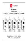
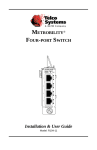
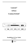
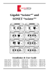
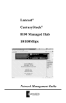
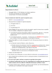
Technical Specifications
Operating Features of the Power Supply
Input Power
ACPS-17HS ___________________ 100-120/200-240V AC
___________________________ 50-60Hz, 2A
DCPS-17HS __________________________ 48V DC, 4.9A
The ACPS-17HS and DCPS-17HS load-sharing power supplies are designed for AC and DC power sources, respectively. Both power supplies are field-replaceable.
Radiance
R5000 Power Supply
Weight
ACPS-17HS ________________________________ 3.25 lb
DCPS-17HS ___________________________________ 3 lb
Environmental
Operating Temperature _____________________ 0º to 50º C
Storage Temperature _____________________ -30º to 70º C
Relative Humidity ___________ 5% to 95% non-condensing
Dimensions ______________________ 7.5"L x 7"W x 3.5"H
___________ (19.1cm L x 17.8cm W x 8.9cm H)
I.T.E.
US E116552
C
PWR
LISTED
DCPS-17HS
DISCONNECT ALL POWER
SOURCES BEFORE SERVICING
_________________
PRODUCT SERVICE
Made
in
USA
DC IN 48V, 4.9A
The information contained in this document is assumed to be correct and
current. The manufacturer is not responsible for errors or omissions and
reserves the right to change specifications at any time without notice.
This publication is protected by the copyright laws of the United States
and other countries, with all rights reserved. No part of this publication
may be reproduced, stored in a retrieval system, translated, transcribed,
or transmitted, in any form, or by any means manual, electric, electronic,
electromagnetic, mechanical, chemical, optical or otherwise, without prior
explicit written permission of METRObility Optical Systems, Inc.
CAUTION
RISK OF ELECTRIC
SHOCK, DO NOT OPEN
C
I.T.E.
US E116552
LISTED
THIS DEVICE COMPLIES WITH PART 15 OF THE FCC RULES,
OPERATION IS SUBJECT TO THE FOLLOWING TWO CONDITIONS:
(1) THIS DEVICE MAY NOT CAUSE HARMFUL INTERFERENCE,
AND (2) THIS DEVICE MUST ACCEPT ANY INTERFERENCE RECEIVED,
INCLUDING INTERFERENCE THAT MAY CAUSE UNDESIRED OPERATION.
PWR
ACPS-17HS
DISCONNECT ALL POWER
SOURCES BEFORE SERVICING
_________________
PRODUCT SERVICE
AC IN
100-120 /
200-240V
50-60Hz,
2A
© 2001 METRObility Optical Systems, Inc.
All rights reserved. Printed in USA.
WARNING
FACTORY DEFAULT
SETTING 115V
CAUTION
RISK OF ELECTRIC
SHOCK, DO NOT OPEN
THIS DEVICE COMPLIES WITH PART 15 OF THE FCC RULES,
OPERATION IS SUBJECT TO THE FOLLOWING TWO CONDITIONS:
(1) THIS DEVICE MAY NOT CAUSE HARMFUL INTERFERENCE,
AND (2) THIS DEVICE MUST ACCEPT ANY INTERFERENCE RECEIVED,
INCLUDING INTERFERENCE THAT MAY CAUSE UNDESIRED OPERATION.
25 Manchester Street, Merrimack, NH 03054 USA
tel: 603-880-1833 • fax: 603-594-2887
www.metrobility.com
Installation and User Guide
5660-000024 B
8/01
Models: ACPS-17HS / DCPS-17HS
When two power supplies are installed in the Radiance
R5000 Central Service Platform, they operate in tandem and
share the load. If the power source to one of the supplies fails
or is removed, the other power supply automatically provides
the entire power load to the platform. This setup provides
both the platform and the network with uninterrupted service.
It also decreases the demand placed upon an individual
power supply, thus prolonging its life.
When the power (PWR) LED on the front panel of the power
supply is lit, it indicates that the power supply is turned on,
connected to an active power source, and providing power to
the platform’s backplane. Because they are load-sharing,
when two power supplies are installed and active in a single
platform, the LEDs on both supplies are lit simultaneously.
An optional display card is available for visible verification of operating status from the
front of the platform. The R500-D, which
must be installed in slot 16 or 17, provides
two LEDs labeled A and B. When lit, these
LEDs indicate that their corresponding
power supplies are installed properly, connected to an active power source, turned on,
and providing power to the platform’s
backplane. When two power supplies are installed and active in a single platform, both
LEDs are lit simultaneously.
PWR
A
B
R500-D
Front Panel
Display Card
Installing the Power Supply
Follow the steps outlined below to install the ACPS-17HS or
DCPS-17HS power supply in the Radiance R5000 Central
Service Platform.
IMPORTANT
Disconnect all power sources before
installing or removing the power supply.
A blank panel must remain installed in any
empty power supply slot.
Do not apply power to the power supply
while it is out of the platform.
Note: The DCPS-17HS is designed to protect against
overheating. The power supply will go into thermal shutdown mode if it is operated above the specified temperature
of 50°C. Normal operation can be reestablished once the
temperature drops to the specified range by power cycling
the unit.
R5000-17HS
I.T.E.
US E116552
C
LISTED
PWR
DCPS-17HS
DISCONNECT ALL POWER
SOURCES BEFORE SERVICING
I.T.E.
US E116552
C
LISTED
PWR
DCPS-17HS
DISCONNECT ALL POWER
SOURCES BEFORE SERVICING
_________________
PRODUCT SERVICE
_________________
PRODUCT SERVICE
Made
in
Made
Caution: A fully loaded platform is rated for 2A AC
maximum current. Make sure that the power supply current is
sufficient to power the platform. Refer to the front panel text
for voltage/current ratings. Reliable grounding of rackmount
equipment must be maintained. Particular attention should
be given to power supply connections other than direct
connections to the branch circuit (e.g. use of power strips).
in
DC IN 48V, 4.9A
CAUTION
RISK OF ELECTRIC
SHOCK, DO NOT OPEN
For AC power supply connections, follow these guidelines:
• Make sure the power switch is in the OFF position (O).
• Plug the AC cord into the connector on the power supply,
then insert the other end of the cord into the AC power
source. If two power supplies have been installed, connect
each power supply to a separate power source.
• Set the power switch to the ON position (I).
• Verify proper connection and operation via the power
(PWR) LED on the power supply front panel. The LED is
lit when the power supply is functioning correctly.
USA
USA
1. Remove the blank panel from the back of the platform.
2. Insert the power supply into the slot. Do not force it into
the platform unnecessarily. It should slide in easily and
evenly.
3. Push gently until the face panel is flush with the platform.
4. Turn the thumb screws clockwise and tighten to secure the
power supply into the platform.
Caution: A fully loaded platform is rated for 4.9A DC
maximum current. Make sure that the power supply current
available is sufficient to power the platform. Refer to front
panel text for voltage/current ratings. The center terminal
connector provides grounding for the platform and must be
maintained. Particular attention should be given to power
supply connections other than direct connections to the
branch circuit (e.g. use of power strips).
DC IN 48V, 4.9A
RISK OF ELECTRIC
SHOCK, DO NOT OPEN
R5000-17HS
C
CAUTION
THIS DEVICE COMPLIES WITH PART 15 OF THE FCC RULES,
OPERATION IS SUBJECT TO THE FOLLOWING TWO CONDITIONS:
(1) THIS DEVICE MAY NOT CAUSE HARMFUL INTERFERENCE,
AND (2) THIS DEVICE MUST ACCEPT ANY INTERFERENCE RECEIVED,
INCLUDING INTERFERENCE THAT MAY CAUSE UNDESIRED OPERATION.
THIS DEVICE COMPLIES WITH PART 15 OF THE FCC RULES,
OPERATION IS SUBJECT TO THE FOLLOWING TWO CONDITIONS:
(1) THIS DEVICE MAY NOT CAUSE HARMFUL INTERFERENCE,
AND (2) THIS DEVICE MUST ACCEPT ANY INTERFERENCE RECEIVED,
INCLUDING INTERFERENCE THAT MAY CAUSE UNDESIRED OPERATION.
I.T.E.
US E116552
LISTED
Important: The terminal block safety cover must be installed
when power is present to prevent burn or energy hazards.
ACPS-17HS
DISCONNECT ALL POWER
SOURCES BEFORE SERVICING
C
I.T.E.
US E116552
LISTED
PWR
ACPS-17HS
DISCONNECT ALL POWER
SOURCES BEFORE SERVICING
_________________
PRODUCT SERVICE
AC IN
100-120 /
200-240V
50-60Hz
2A
Applying Power
DC Power Supply (DCPS-17HS)
For DC power supply connections, follow these guidelines:
• Make sure the power switch is in the OFF position (O).
• Remove the plastic safety cover to expose the terminals.
• Connect the wire leads to the appropriate terminals. There
is one each for a positive, a negative and a platform
ground. To make a connection, loosen the terminal screw,
insert the exposed wire, then tighten the screw. If two
power supplies have been installed, connect each power
supply to a separate power source.
• Replace the plastic safety cover over the terminal block.
• Set the power switch to the ON position (I).
• Verify proper connection and operation via the power
(PWR) LED on the power supply front panel. The LED is
lit when the power supply is functioning correctly.
PWR
_________________
PRODUCT SERVICE
WARNING
CAUTION
RISK OF ELECTRIC
SHOCK, DO NOT OPEN
AC Power Supply (ACPS-17HS)
The ACPS-17HS includes a standard North American 3-pin
power cord which is UL (USA), CSA or CUL (Canada) listed
or approved. For installation in regions outside North
America, replace the power cord with a cord approved by appropriate safety agencies. The cord must have a CEE-22 standard V female connector on one end and meet IEC 320-030
specifications. European power cords must be harmonized
and designated with a HAR marking on the outside of the
cord jacket to comply with the CENELEC Harmonized
Document HD-21.
WARNING
The default voltage setting on the ACPS-17HS is
115V AC. Before applying power, make sure the
voltage switch is set appropriately for the voltage
source in your region.
AC IN
100-120 /
200-240V
50-60Hz
2A
WARNING
FACTORY DEFAULT
SETTING 115V
FACTORY DEFAULT
SETTING 115V
CAUTION
THIS DEVICE COMPLIES WITH PART 15 OF THE FCC RULES,
OPERATION IS SUBJECT TO THE FOLLOWING TWO CONDITIONS:
(1) THIS DEVICE MAY NOT CAUSE HARMFUL INTERFERENCE,
AND (2) THIS DEVICE MUST ACCEPT ANY INTERFERENCE RECEIVED,
INCLUDING INTERFERENCE THAT MAY CAUSE UNDESIRED OPERATION.
RISK OF ELECTRIC
SHOCK, DO NOT OPEN
THIS DEVICE COMPLIES WITH PART 15 OF THE FCC RULES,
OPERATION IS SUBJECT TO THE FOLLOWING TWO CONDITIONS:
(1) THIS DEVICE MAY NOT CAUSE HARMFUL INTERFERENCE,
AND (2) THIS DEVICE MUST ACCEPT ANY INTERFERENCE RECEIVED,
INCLUDING INTERFERENCE THAT MAY CAUSE UNDESIRED OPERATION.
Replacing the Power Supply
To remove an ACPS-17HS or DCPS-17HS power supply
from the Radiance R5000 Central Service Platform, perform
the following steps.
IMPORTANT
Follow all precautions described in the box under
“Installing the Power Supply.”
1. Remove the power cord or wire leads from the power
supply.
2. Turn the thumb screws counterclockwise to loosen the
power supply from the platform.
3. Remove the power supply from the platform.
4. Install another power supply or a blank panel into the
empty slot. Refer to “Installing the Power Supply” for
installation instructions.