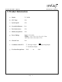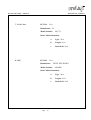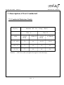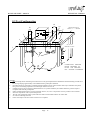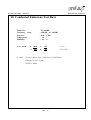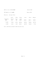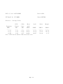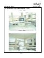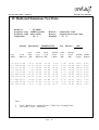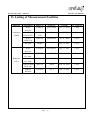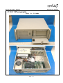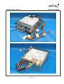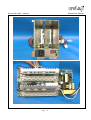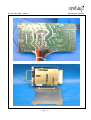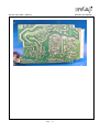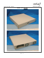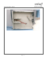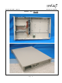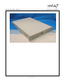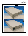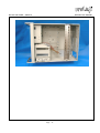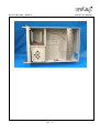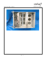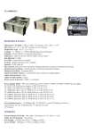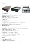
1
NVLAP LAB CODE:200097-0
REPORT NO. :E890381
FCC DoC TEST REPORT
According to
FCC Part 15 Subpart B
Test
: Redundant Power Supply
Item
Model
: TC-300R8, TC-250R8, TC-250R9, TC-300R8A, TC-400R8A,
TC-400R8, TC-300R6, TC-400R6, TC-500R8A
No.
: I-STAR COMPUTER CO., LTD
Responsible
Party
Address
2F, NO.33 LANE42, CHUNG SHIN NORTH ST., SAN
CHUNG CT, TAIPEI, TAIWAN, R. O. C.
Test Engineer :
Test Date
:
Issued Date
: JULY 13. 2002
NVLAP Signature : _______________________
Peter Kao / Director
•The test report shall not be reproduced except in full, without the written approval of
the laboratory.
•The report must not be used by the client to claim product endorsement by NVLAP or any
agency of the United States government.
•This report is only for item test which described in page 4 .
•The testing result in this report are traceable to national and international standard .
PEP TESTING LABORATORY
12-3Fl, No. 27-1, Lane 169, Kang-Ning St., Hsi-Chin.
Taipei Hsien, Taiwan, R. O. C.
TEL : 8862-26922097 FAX : 8862-26956236
Page 1
NVLAP LAB CODE:200097-0
REPORT NO. :E890381
Table of Contents
1.
SCOPE
3
2.
PRODUCT INFORMATION
4
3.
EUT DESCRIPTION AND TEST METHODS
5
4.
MODIFICATION(S)
6
5.
TEST SOFTWARE USED
7
6.
SUPPORT EQUIPMENT USED
8
7.
DESCRIPTION OF TEST CONDUCTED
13
8.
DESCRIPTION OF TEST RADIATED
14
9.
CONDUCTED TEST CONFIGURATION PHOTO.
17
10.
CONDUCTED EMISSIONS TEST DATA
18
11.
RADIATED TEST CONFIGURATION PHOTO.
27
12.
RADIATED EMISSIONS TEST DATA
28
13.
LISTING OF MEASUREMENT FACILITIES
30
14.
DUTIES OF THE RESPONSIBLE PARTY
31
15.
LABELLING REQUIREMENTS
32
16.
INFORMATION TO THE USER
33
17.
EUT PHOTOGRAPHS
34
Page 2
NVLAP LAB CODE:200097-0
REPORT NO. :E890381
1. Scope
Measurement and determination of electromagnetic emissions (EME) of radio frequency devices
including intentional and/or unintentional radiators for compliance with the technical rules and
regulations of the Federal Communications Commission under ET Docket 95-19 Declaration of
Conformity(DoC).
Responsible Party*:
I-STAR COMPUTER CO., LTD
Address: 2F, NO.33 LANE42, CHUNG SHIN NORTH ST., SAN CHUNG CT, TAIPEI,
TAIWAN, R. O. C.
Contact Person: David Yeh / Manager
Phone
No.:
886-2-2999-5951
Fax No. :
² Regulation:
FCC Part 15 & Part 2; Docket 95-19
² Limitation:
CISPR 22 CLASS B
² Test Procedure:
ANSI C63.4(1992)
² Test Item:
Redundant Power Supply
² Model No.:
TC-300R8
² Serial No.:
N/A
² Place of Test:
PEP Testing Laboratory
886-2-2999-5933
12-3Fl, No. 27-1, Lane 169, Kang-Ning St., Hsi-Chin.
Taipei Hsien, Taiwan, R. O. C.
TEL : 8862-26922097 FAX : 8862-26956236
Measurement Uncertainty :
The uncertainty of the testing result is given as below . The method of uncertainty
Calculation is based on NIST Technical Note 1297 .
0.15 ∼ 30
30 ∼ 1000
Frequency ( MHz )
1.77 (dB)
Combined Uncertainty μc
Page 3
2.08 (dB)
NVLAP LAB CODE:200097-0
REPORT NO. :E890381
2. Product Information
a. Model:
TC-300R8
b. CPU Type:
N/A
c.
N/A
System speed:
d. Crystal/Oscillator(s) :N/A
e.
Port/connector(s) :
f.
Memory Expansion: N/A
N/A
g. Power Rating:
Input: 115V-230V
Output: +3.3V/+5V/+12V/-5V/-12V/+5Vsb
14A /30A/ 12A/ 0.5A/ 0.8A/ 0.75A
h. Chassis Used:
N/A
i.
Condition of the EUT :
3 Engineering Sample
□ Prototype Sample
□ Production Sample
j.
Test Item Receipt Date :
JULY
/
Page 4
06
/ 2000
NVLAP LAB CODE:200097-0
REPORT NO. :E890381
3. EUT Description and Test Methods
The equipment under test (EUT) is redundant power supply model No. TC-300R8 ( or
TC-250R8, TC-250R9, TC-300R8A, TC-400R8A, TC-400R8, TC-300R6, TC-400R6,
TC-500R8A) all of models are identical product and identified by applicant , we only tested
model TC-300R8 , for more detail information about EUT , please refer the user’s manual .
Test method : the EUT was put inside a PC system to test and the system was enabled
by “H” character program , the worst case testing result provided in this
report .
As pre-scan , we took radiated emission first , EUT configuration including peripheral devices
placement and data cables coupling was compliant with ANSI C63.4 requirement , test engineer
tried to find the worst data cables coupling in order to perform the final test which conducted
emission and radiated emission would keep the same configuration under test.
Page 5
NVLAP LAB CODE:200097-0
REPORT NO. :E890381
4. Modification(s):
The applicant upon signing the Declaration of Conformity agrees to incorporate the above
modification(s) into all production units (see attached sample Declaration of Conformity).
N/A
Page 6
NVLAP LAB CODE:200097-0
REPORT NO. :E890381
5. Test Software Used
A test program which generates a complete line of continuously repeating “H” pattern is used
as the software test program. The program was executed as follow :
a. Read and write to the disk drives.
b. Send signal to check keyboard .
c. Send H pattern to the parallel port device (Printer).
d. Send H pattern to the serial port device (Modem).
e. Send H pattern to the video port device (Monitor).
f.
Repeat the above steps.
Page 7
NVLAP LAB CODE:200097-0
REPORT NO. :E890381
6. Support Equipment Used
1. Keyboard
FCC ID: E5XKB5121WTH0110
Manufacture: BTC
Model Number: 5121W
Data Cable Information:
a. Type : Shielded , Detachable
b. Length :
1
m
c. Back Shell : Metal
2. Monitor
FCC ID:Declaration of Conformity(DoC)
Manufacture: SAMSUNG
Model Number: 550S
Power Cord:Shielded, Detachable, 1.2m
Data Cable Information:
a. Type : Shielded , Detachable
b. Length :
1
m
c. Back Shell : Metal
3. Printer
FCC ID: B94C2642X
Manufacture: HEWLETT-PACKARD
Model Number: HP400
Power Supply Type: N/A
Power Cord:Shielded, Detachable, 1.2m
Data Cable Information:
a. Type :N/A
b. Length :N/A
c. Back Shell : N/A
Page 8
NVLAP LAB CODE:200097-0
4. Modem
×2
REPORT NO. :E890381
FCC ID: IFAXDM1414
Manufacture: ACEEX
Model Number:
Power Supply Type:
Power Cord:Shielded, Detachable, 1.2m
Data Cable Information:
5. Mouse
a.
Type : Shielded , Detachable
b.
Length :
c.
Back Shell : Metal
m
FCC ID: DZl211106
Manufacture: LOGITECH
Model Number: M-S43
Data Cable Information:
6. Mother Board
a.
Type : N/A
b.
Length : N/A
c.
Back Shell : N/A
FCC ID: N/A
Manufacture: INTEL
Model Number:SE440BX-2
Data Cable Information:
Page 9
a.
Type :N/A
b.
Length :N/A
c.
Back Shell : N/A
NVLAP LAB CODE:200097-0
7. VGA Card
REPORT NO. :E890381
FCC ID: N/A
Manufacture:S3
Model Number: 86C775
Data Cable Information:
8. CPU
a.
Type : N/A
b.
Length : N/A
c.
Back Shell : N/A
FCC ID: N/A
Manufacture: INTEL PEUTIUMⅡ
Model Number: 450MHZ
Data Cable Information:
Page 10
a.
Type : N/A
b.
Length : N/A
c.
Back Shell : N/A
NVLAP LAB CODE:200097-0
9. Ram
REPORT NO. :E890381
FCC ID: N/A
Manufacture:APACER
Model Number: 64MB
Data Cable Information:
10. Hard Disk
a.
Type : N/A
b.
Len gth : N/A
c.
Back Shell : N/A
FCC ID: N/A
Manufacture:QUANDUM
Model Number: 2.1GB
Data Cable Information:
Page 11
a.
Type : N/A
b.
Length : N/A
c.
Back Shell : N/A
NVLAP LAB CODE:200097-0
11. Floppy
REPORT NO. :E890381
FCC ID: N/A
Manufacture:MITSUMI
Model Number:1.44MB
Data Cable Information:
12. CD ROM
a.
Type : N/A
b.
Length : N/A
c.
Back Shell : N/A
FCC ID: N/A
Manufacture:ACER
Model Number:32X 632A-006
Data Cable Information:
Page 12
a.
Type : N/A
b.
Length : N/A
c.
Back Shell : N/A
NVLAP LAB CODE:200097-0
REPORT NO. :E890381
7. Description of Test Conducted
7.1 Conducted Emissions Limits
Frequency
Maximum RF Line Voltage dB(uV)
Class A
Class B
MHz
QUASIPEAK
AVERAGE
QUASIPEAK
AVERAGE
0.15 - 0.50
79
66
66-56
56-46
0.50 - 5.0
73
60
56
46
5.0 - 30
73
60
60
50
Remarks : In the above table, the tighter limit applies at the band edges.
Page 13
NVLAP LAB CODE:200097-0
REPORT NO. :E890381
8. Description of Test Radiated
8.1 Radiated Emissions
Preliminary measurements were made indoors chamber at 3 meter using broadband antennas,
broadband amplifier, and spectrum analyzer to determine the frequency producing the
maximum EME. Appropriate precaution was taken to ensure that all EME from the EUT
were maximized and investigated. The system configuration, clock speed, mode of operation
or video resolution, turntable azimuth with respect to the antenna were noted for each
frequency found. The spectrum was scanned from 30 to 1000 MHz using logbicon antenna.
Above 1GHz, linearly polarized double ridge horn antenna was used.
Final measurements were made outdoors at 10-meter test range using logbicon antenna and
horn antenna. The test equipment was placed on a wooden bench situated on a 1.5x1 meter
area adjacent to the measurement area. Sufficient time for the EUT, support equipment, and
test equipment was allowed in order for them to warm up to their normal operating
condition. Each frequency found during pre-scan measurements was re-examined and
investigated using Quasi-Peak Adapter. The detector function was set to CISPR quasi-peak
mode and the bandwidth of the receiver was set to 120kHz.
The turntable containing the system was rotated; the antenna height was varied 1 to 4
meters and stopped at the azimuth or height producing the maximum emission. Each
emission was maximized by: varying mode of operation or resolution; clock or data
exchange speed; scrolling H pattern to the EUT and/or support equipment, and powering
the monitor from the floor mounted outlet box and the computer aux AC outlet , if
applicable; and changing the polarity of the antenna, whichever determined the worst-case
emission. Photographs of the worst-case emission can be seen in radiated emission test
photo.
Page 14
NVLAP LAB CODE:200097-0
REPORT NO. :E890381
8.2 Test Configuration
10
cm
10
cm
EUT
NONCONDUCTIVE
TABLE 1.5 x 1 METER
5
5
6
80 cm TO
GROUND PLANE
7
4
2
1
8
3
40 cm
8
CONDUCTING GROUND
PLANE EXTENDS AT
LEAST 0.5m BEYOND
EUT SYSTEM FOOTPRINT
LEGEND
1.
Interconnecting cables which hang closer than 40 cm to the ground plane shall be folded back and forth forming a bundle 30 to
40 cm long. hanging approximately in the middle between ground plane and table.
2.
I/O cables which are connected to a peripheral hall be bundled in center. The end of the cable may b terminated if required
using correct terminating impedance. The total length shall not exceed 1 m.
3.
If LISN are kept in the test setup for radiated emissions, it is preferred that they be installed under the ground if requires
receptacle flush with the ground plane.
4.
Cables of hand-operated devices, such as keyboards, mouses, etc., have to be placed as close as possible to the controller.
5.
Non-EUT components of EUT system being tested.
6.
The rear of all components of the system under test shall be located flush with the rear of the table.
7.
No vertical conducting wall used.
8.
Power cords drape to the floor and are routed over to receptacle.
Page 15
NVLAP LAB CODE:200097-0
REPORT NO. :E890381
8.3 Radiated Emission Limits
Limits for radiated disturbance of Class A ITE at
a measuring distance of 10 m
Frequency
MHz
Field Strength
dB(μV/m)
30
to
230
40
230
to
1 000
47
NOTES
1 The lower limit shall apply at the transition frequency.
2 Additional provisions may be required for cases where
interference occurs.
Limits for radiated disturbance of Class B ITE at
a measuring distance of 10 m
Frequency
MHz
Field Strength
dB(μV/m)
30
to
230
30
230
to
1 000
37
NOTES
1 The lower limit shall apply at the transition frequency.
2 Additional provisions may be required for cases where
interference occurs.
Page 16
NVLAP LAB CODE:200097-0
REPORT NO. :E890381
9. Conducted Test Configuration Photo.
< FRONT VIEW >
Page 17
NVLAP LAB CODE:200097-0
REPORT NO. :E890381
10. Conducted Emissions Test Data
Model No.
Frequency range
Detector
Temperature
Humidity
Test Data :
※ Note
#
#
: TC-300R8
: 150KHz to 30MHz
: Peak Value
: 28 ℃
: 65 %
1020
1025
#
#
195
189
< LINE >
< NEUTRAL >
1. Level = Meter read + Cable Loss + LISN Factor
2. Margin = Level – Limit
3. LISN = AMN
Page 18
Page 19
DaTe of test: 06/29/2000
Data #:1020
EUT Model No :TC-300R8
Phase:LINE
Detector : Peak Value
LISN
Cable
Meter
Level
Frequency
Factor
Loss
read
(MHz)
(dB)
(dB)
(dBuV)
(dBuV)
----------------------0.153
0.10
0.90
47.01
48.01
0.157
0.10
0.93
64.20
65.23
0.176
0.10
1.05
53.61
54.76
0.251
0.10
1.58
49.40
51.08
0.461
0.10
1.66
41.80
43.56
0.989
0.10
1.75
41.40
43.25
2.273
0.12
1.70
38.59
40.41
6.951
0.38
1.64
38.59
40.61
11.870
0.58
1.50
38.40
40.48
20.056
0.90
1.58
29.61
32.09
Note: LISN Factor means LISN insertion loss.
Page 20
Limit
Margin
(dBuV)
-----65.82
65.60
64.68
61.73
56.67
56.00
56.00
60.00
60.00
60.00
(dBuV)
------17.81
-0.37
-9.92
-10.65
-13.11
-12.75
-15.59
-19.39
-19.52
-27.91
Page 21
DaTe of test: 06/29/2000
Data #:195
EUT Model No :TC-300R8
Phase:LINE
Detector : Average Value
Frequency
(MHz)
------0.157
0.176
LISN
Factor
(dB)
----0.10
0.10
Cable
Loss
(dB)
---0.93
1.05
Meter
read
(dBuV)
----29.40
45.61
Level
Limit
Margin
(dBuV)
-----30.43
46.76
(dBuV)
-----55.60
54.68
(dBuV)
------25.17
-7.92
Note: LISN Factor means LISN insertion loss.
Page 22
Page 23
DaTe of test: 06/29/2000
Data #:1025
EUT Model No :TC-300R8
Phase:NEUTRAL
Detector : Peak Value
LISN
Cable
Meter
Level
Frequency
Factor
Loss
read
(MHz)
(dB)
(dB)
(dBuV)
(dBuV)
----------------------0.151
0.10
0.88
62.41
63.39
0.253
0.10
1.57
50.80
52.47
0.387
0.10
1.73
44.19
46.02
0.716
0.10
1.73
40.59
42.42
1.203
0.10
1.73
41.60
43.43
2.201
0.11
1.69
37.81
39.61
4.822
0.28
1.74
33.20
35.22
8.367
0.52
1.61
36.00
38.13
14.213
0.86
1.48
37.20
39.54
23.263
1.24
1.66
26.79
29.69
Note: LISN Factor means LISN insertion loss.
Page 24
Limit
Margin
(dBuV)
-----65.96
61.64
58.12
56.00
56.00
56.00
56.00
60.00
60.00
60.00
(dBuV)
------2.57
-9.17
-12.10
-13.58
-12.57
-16.39
-20.78
-21.87
-20.46
-30.31
Page 25
DaTe of test: 06/29/2000
Data #:189
EUT Model No :TC-300R8
Phase:NEUTRAL
Detector : Average Value
LISN
Cable
Meter
Level
Frequency
Factor
Loss
read
(MHz)
(dB)
(dB)
(dBuV)
(dBuV)
----------------------0.151
0.10
0.88
28.20
29.18
0.253
0.10
1.57
44.80
46.47
Note: LISN Factor means LISN insertion loss.
Page 26
Limit
Margin
(dBuV)
-----55.96
51.64
(dBuV)
------26.78
-5.17
NVLAP LAB CODE:200097-0
REPORT NO.:E890381
11. Radiated Test Configuration Photo.
< FRONT VIEW >
< REAR VIEW >
Page 27
NVLAP LAB CODE:200097-0
REPORT NO.:E890381
12. Radiated Emissions Test Data
Model No.
Frequency range
Frequency range
Temperature
Antenna
: TC-300R8
: 30MHz to 1GHz
: above 1GHz
:
28 o C
Detector
Detector
Humidity
polarization : HORIZONTAL ;
Freq.
(MHz)
Over
Level
Limit
(dBuV/m) (dB)
Limit
Read
Line
Level
(dBuV/m) (dB)
Antenna
Factor
(dB/m)
70.224
121.165
140.317
174.728
201.179
255.492
389.314
417.084
479.485
565.129
21.89
18.48
22.90
22.55
21.00
23.40
23.19
28.11
25.39
27.89
30.00
30.00
30.00
30.00
30.00
37.00
37.00
37.00
37.00
37.00
5.14
11.50
10.60
8.67
8.96
12.84
15.34
16.77
17.29
18.75
- 8.11
-11.52
- 7.10
- 7.45
- 9.00
-13.60
-13.81
- 8.89
-11.61
- 9.11
35.16
24.46
29.90
30.88
28.93
26.83
23.28
26.66
23.00
23.39
: Quasi-Peak Value
: Quasi-Peak/Average Value
: 65 %
Test distance :
Cable
Loss
(dB)
1.40
2.20
2.20
2.50
2.71
3.33
4.58
4.78
5.10
5.59
Preamp
Factor
(dB)
Azimuth Antenna
(°
angle) High(m)
19.81
19.68
19.80
19.50
19.60
19.60
20.01
20.10
20.00
19.84
136.1
140.7
140.8
137.6
143.5
140.2
133.8
134.1
142.5
142.9
Note :
1.
2.
Level = Read Level + Antenna Factor + Cable Loss – Preamp Factor
Over Limit = Level – Limit Line
Page 28
10m ;
4.00
4.00
4.00
4.00
4.00
4.00
4.00
1.30
1.30
1.50
NVLAP LAB CODE:200097-0
Model No.
Frequency range
Frequency range
Temperature
REPORT NO.:E890381
: TC-300R8
: 30MHz to 1GHz
: above 1GHz
: 34o C
Antenna polarization :
Over
Freq.
(MHz)
Level
(dBuV/m)
72.005
125.070
148.153
171.094
201.185
252.109
381.419
409.384
433.845
564.318
22.64
22.52
18.00
16.67
22.09
21.11
22.79
25.11
28.06
27.51
Limit
(dB)
- 7.36
- 7.48
-12.00
-13.33
- 7.91
-15.89
-14.21
-11.89
- 8.94
- 9.49
Limit
Detector : Quasi-Peak Value
Detector : Quasi-Peak/Average Value
Humidity :
63 %
VERTICAL ;
Read
Test distance :
Antenna Cable
Preamp
Line
Level
(dBuV/m) (dB)
Factor
(dB/m)
Loss
(dB)
Factor
(dB)
Azimuth
(°
angle)
Antenna
High(m)
30.00
30.00
30.00
30.00
30.00
37.00
37.00
37.00
37.00
37.00
5.42
11.50
10.12
9.10
8.96
12.31
14.88
16.65
16.36
18.76
1.40
2.20
2.36
2.50
2.71
3.31
14.88
16.65
16.36
18.76
19.84
19.60
19.72
19.50
19.60
19.54
19.95
20.10
20.03
19.84
137.6
149.9
136.3
137.7
142.0
138.6
137.2
135.6
141.5
143.5
1.00
1.00
1.00
1.00
1.00
1.00
1.00
1.30
1.40
1.00
35.66
28.42
25.24
24.57
30.02
25.03
23.37
23.81
26.86
23.01
Note :
1.
2.
10m ;
Level = Read Level + Antenna Factor + Cable Loss – Preamp Factor
Over Limit = Level – Limit Line
Page 29
NVLAP LAB CODE:200097-0
REPORT NO.:E890381
13. Listing of Measurement Facilities
Emission
Conduction
(EMI4)
Radiation
(O.P 1)
Instrument
Model No.
Serial No.
Cal. Date
Cal . Interval
R&S
Receiver
ESHS10
830223/008
Oct. 21, 2000
1 Year
Rolf Heine
LISN (EUT)
NNB-4/
63TL
98008
Non-EUT LISN
N/A
R&S
LISN (2’d)
ESH3-Z5
844982/039
Jul. 21, 2000
1 Year
RF cable
RG400
Apr. 15, 2001
1 Year
R&S
Receiver
ESVS30
863342/012
Apr. 17, 2001
1 Year
R&S
Pre-Amp.
ESMI-Z7
612278/011
May 19, 2001
1 Year
Anritsu
Pre-Amp.
MH648A
M15080
Jun. 01, 2001
1 Year
COM-POWER
Horn Ant.
AH-118
10056
Aug. 24, 2000
1 Year
EMCO
RF bable
175 series
No. 1
Apr. 15, 2001
1 Year
Page 30
NVLAP LAB CODE:200097-0
REPORT NO.:E890381
14. Duties of The Responsible Party
The responsible party upon signing or accepting the Declaration of Conformity as specified in
Section 2.906 of the FCC Rules hereby agrees to the duties listed below.
§
2.1073(a).
The responsible party warrants that each unit of equipment marketed under DoC is identical to the unit
tested and found acceptable with the standards and that the records maintained by the responsible party
continue to reflect the equipment being produced is within the variation that can be expected due to
quantity production and testing on a statistical bass.
§
2.1073(b).
The responsible party must have a written statement from the manufacturer or accredited test laboratory
that the equipment complies with the appropriate technical standards.
§
2.1073(c).
In case of transfer of control of equipment, as in the case of sale or merger, the new responsible party
shall bear the responsibility of continued compliance of the equipment.
§
2.1073(d).
Equipment shall be retested if any modifications or changes are made that could adversely affect the
emanation characteristics of the equipment.
§
2.1073(e).
If any modifications or changes made by anyone other than the responsible party, the party making the
modifications of changes, if located within the U.S., becomes the new responsible part. The new
responsible party must comply with all provisions for the DoC, including having test data on file
demonstrating that the product continues to comply with all of the applicable technical standards.
§
2.1075(a)(1).
The responsible party shall maintain records of the original design drawings and specifications and all
changes made to the product that may affect compliance.
§
2.1075(a)(2).
The responsible party shall maintain records of the procedures used for production inspection and
testing to insure the conformance with the FCC Rules.
§
2.946(a)(1).
The test report data shall be provided to the FCC within 14 days of delivery of request. The test
sample(s) shall be provided within 60 days of delivery of request.
§
2.946(b)
In case involving harmful interference or safety of life or property, the production sample must be
provided within 60 days, but not less than 14 days. Failure to comply with such a request with the
time frame shown may be cause for forfeiture, pursuant to Section 1.80 of Part 1 of the FCC Rules.
*The Responsible Party is the manufacturer, system integrator, or the importer as defined in Section
2.909 of the FCC Rules. The Rules. The Responsible Party for a DoC must be located within the
United States as specified in Section 2.1077.
Page 31
NVLAP LAB CODE:200097-0
REPORT NO.:E890381
15. Labelling Requirements
per §
§
2.1074 & 15.19; Docket 95-19
The sample label shown below shall be permanently affixed at a conspicuous location on the
device, instruction manual or pamphlet supplied to the user and be readily visible to the
purchaser at the time of purchase. However, when the device is so small wherein placement
of the label with specified statement is not practicable, only the trade name, model number,
and the FCC logo must be displayed on the device per Section §
15.19 (b)(2).
Trade Name
Model Number
Tested To Comply
With FCC Standards
FOR HOME OR OFFICE USE
Page 32
NVLAP LAB CODE:200097-0
REPORT NO.:E890381
16. Information To The User
For a Class B digital device or peripheral, the instructions furnished the user shall include the
following or similar statement, placed in a prominent location in the text of the manual:
Federal Communications Commission (FCC) Statement
This equipment has been tested and found to comply with the limits for a Class B digital
device, pursuant to Part 15 of the FCC Rules. These limits are designed to provide reasonable
protection against harmful interference in a residential installation. This equipment generates,
uses and can radiate radio frequency energy and, if not installed and used in accordance with
the instruction, may cause harmful interference to radio communications. However, there is
no guarantee that interference will not occur in a particular installation. If this equipment does
cause harmful interference to radio or television reception, which can be determined by
turning the equipment off and on, the user is encouraged to try to correct the interference by
one or more of the following measures :
-
Reorient or relocate the receiving antenna.
Increase the separation between the equipment and receiver .
Connect the equipment into an outlet on a circuit different from that
to which the receiver is connected .
Consult the dealer or an experienced radio / TV technician for help .
Page 33
NVLAP LAB CODE:200097-0
REPORT NO.:E890381
17. EUT Photographs
Model
No. : TC-300R8
Page 34
NVLAP LAB CODE:200097-0
REPORT NO.:E890381
Page 35
NVLAP LAB CODE:200097-0
REPORT NO.:E890381
Page 36
NVLAP LAB CODE:200097-0
REPORT NO.:E890381
Page 37
NVLAP LAB CODE:200097-0
REPORT NO.:E890381
Page 38
NVLAP LAB CODE:200097-0
REPORT NO.:E890381
Page 39
NVLAP LAB CODE:200097-0
REPORT NO.:E890381
MODEL
NO. : JOY-294A
Page 40
NVLAP LAB CODE:200097-0
REPORT NO.:E890381
Page 41
NVLAP LAB CODE:200097-0
REPORT NO.:E890381
MODEL
NO. : JOY-298
Page 42
NVLAP LAB CODE:200097-0
REPORT NO.:E890381
Page 43
NVLAP LAB CODE:200097-0
REPORT NO.:E890381
MODEL
NO. :JOY- 528E
Page 44
NVLAP LAB CODE:200097-0
REPORT NO.:E890381
Page 45
NVLAP LAB CODE:200097-0
REPORT NO.:E890381
MODEL
NO. : JOY-565ATX
Page 46
NVLAP LAB CODE:200097-0
REPORT NO.:E890381
Page 47
NVLAP LAB CODE:200097-0
REPORT NO.:E890381
MODEL
NO. : JOY-587ATX
Page 48
NVLAP LAB CODE:200097-0
REPORT NO.:E890381
Page 49
NVLAP LAB CODE:200097-0
REPORT NO.:E890381
MODEL
NO. : JOY-828CATX
Page 50
NVLAP LAB CODE:200097-0
REPORT NO.:E890381
Page 51
NVLAP LAB CODE:200097-0
REPORT NO.:E890381
MODEL
NO. : JOY-888ATX
Page 52
NVLAP LAB CODE:200097-0
REPORT NO.:E890381
Page 53
DECLARATION OF CONFORMITY CERTIFICATE
Responsible Party :
I-STAR COMPUTER CO., LTD
Address :
2F, NO.33 LANE42, CHUNG SHIN NORTH ST., SAN CHUNG CT,
TAIPEI, TAIWAN, R. O. C.
Contact Person :
David Yeh / Manager
Equipment :
Redundant Power Supply
Model No.:
TC-300R8, TC-250R8, TC-250R9, TC-300R8A, TC-400R8A,
TC-400R8, TC-300R6, TC-400R6, TC-500R8A
Traceability:
FCC Part 15 & Part 2; Docket 95-19
Limitation:
CISPR 22 CLASS B
Date of issued:
JULY 13, 2002
Report No.:
E890381
The device bearing the trade name and model specified above has been shown to comply with the
applicable technical standards as indicated in the measurement report and was tested in accordance
with the measurement procedures specified in ANSI C63.4-1992. (See Test Report if any
modifications were made for compliance.)
PEP certifies that no party to this application has been denied the FCC benefits pursuant to Section
5301 of the Anti-Drug Abuse Act of 1988, 21 U.S.C. 853(a).
NVLAP LAB CODE:200097-0
Peter Kao/NVLAP Signatory
DECLARATION OF CONFORMITY
This device complies with Part 15 of the FCC Rules. Operation is subject
to the following two conditions: (1) this device may not cause harmful
interference, and (2) this device must accept any interference received,
including interference that may cause undesired operation.
Responsible Party:
I-STAR COMPUTER CO., LTD
Address:
2F, NO.33 LANE42, CHUNG SHIN NORTH ST.,
SAN CHUNG CT, TAIPEI, TAIWAN, R. O. C.
Contact Person:
David Yeh / Manager
Phone
886-2-2999-5951
No.:
Equipment
Model No.
:
:
Fax No.:
886-2-2999-5933
Redundant Power Supply
TC-300R8, TC-250R8, TC-250R9, TC-300R8A, TC-400R8A,
TC-400R8, TC-300R6, TC-400R6, TC-500R8A
We hereby declare that the equipment bearing the trade name and model number
specified above was tested conforming to the applicable FCC Rules under the
most accurate measurement standards possible, and that all the necessary steps
have been taken and are in force to assure that production units of the same
equipment will continue to comply with the Commission s requirements.
Signature
Date