1
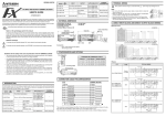
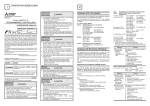
JY997D29701A TYPE QTY DEVICE TYPE MASS Kg (lbs) - - 0.15(0.33) 32 24V DC Sink - - - 0.2(0.44) FX2NC-16EYT - - 16 Transistor Sink 0.15(0.33) FX2NC-32EYT - - 32 Transistor Sink 0.2(0.44) Safety Precaution (Read these precautions before use.) FX2NC-16EX-T 16 24V DC Sink - - - 0.15(0.33) This manual classifies the safety precautions into two categories: FX2NC-16EYR-T - 16 Relay - 0.2(0.44) Operation indication LED is lit when coil is energized *1 For the product life of relay contacts, refer to the FX3UC Series User's Manual Hardware Edition. 2.4 External Dimensions 2.4.1 FX2NC-16EX, FX2NC-32EX, FX2NC-16EYT, FX2NC-32EYT Indicates that incorrect handling may cause hazardous conditions, resulting in medium or slight personal injury or physical damage. 2.1 General Specifications JY997D28601 Extractions of descriptions of input/output specifications, wiring and installation of FX 3UC - MT/D, FX 3UC - MT/DSS from FX 3U C S eries User's Manual Hardware Edition. For the detailed explanation, refer to the FX3UC Series User's Manual - Hardware Edition. JY997D28701 FX3UC Series User’s Manual MODEL CODE: - Hardware Edition 09R519 Explains the FX3UC Series PLC specifications for I/O, wiring, installation, and maintenance. How to obtain manuals For product manuals or documents, consult with the Mitsubishi Electric dealer from where you purchase your product. DESIGN PRECAUTIONS • Make sure to have the following safety circuits outside of the PLC to ensure safe system operation even during extension power supply unit or PLC failure.Otherwise,malfunctions may cause serious accidents. 1) Most importantly, have the following: an emergency stop circuit, a protection circuit, an interlock circuit for opposite movements (such as normal vs. reverse rotation), and an interlock circuit (to prevent damage to the equipment at the upper and lower positioning limits). X0 X0 X0 X0 X1 X1 X1 X1 X2 X2 X2 X2 X3 X3 X3 X3 X4 X4 X4 X4 X5 X5 X5 X5 X6 X6 X6 X6 X7 X7 X7 X7 COM COM COM COM IN X0 X1 X2 X3 X4 X5 X6 X7 COM COM X0 X1 X2 X3 X4 X5 X6 X7 COM COM FX2NC-16EX,FX2NC-32EX,FX2NC-16EX-T Input voltage 24V DC +20%, -15% Input switching current 24V DC, 5mA OFF Æ ON >3.5mA ON Æ OFF <1.5mA Response time 10ms Circuit isolation Photocoupler Operation indication Transistor Output Specifications FX2NC-16EYT, FX2NC-32EYT Switched voltage (resistive load) 5 - 30V DC Rated current / N points 0.1A/1point Make sure that the total load current of the 8 resistance load points is 0.8 A or less. Max. Inductive load 2.4W/24V DC Response time (approx.) OFF Æ ON ON Æ OFF Open circuit current leakage Power supply connectors for input extension blocks FX2NC-16EYT LED is lit 2.3 Output Specifications 2.3.1 DIN Rail: 35mm (1.38) <0.2ms (100mA/24V DC), <0.2ms (100mA/24V DC), 0.1mA/30V DC Circuit isolation Photocoupler Operation indication LED is lit when photocoupler is driven OUT Y0 Y0 Y1 Y1 Y2 Y2 Y3 Y3 Y4 Y4 Y5 Y5 Y6 Y6 Y7 Y7 COM1 COM1 FX2NC-32EYT OUT OUT Y0 Y0 Y0 Y0 Y1 Y1 Y1 Y1 Y2 Y2 Y2 Y2 Y3 Y3 Y3 Y3 Y4 Y4 Y4 Y4 Y5 Y5 Y5 Y5 Y6 Y6 Y6 Y6 Y7 Y7 Y7 Y7 COM1 COM1 COM2 COM2 FX2NC-16EYR-T Lower Description FX2NC-16EX-T IN 2.2 Input Specifications Input current Manual No. X0 X0 X1 X1 X2 X2 X3 X3 X4 X4 X5 X5 X6 X6 X7 X7 COM COM IN The general specifications are equivalent to the PLC main unit. For the general specifications, refer to the FX3UC (D,DSS) Series Hardware Manual. 13 (0.51) may FX2NC-32EX IN Lower 2. Specifications 2.5 Terminal Layouts FX2NC-16EX FX2NC-32E 26.2(1.03) FX2NC-16E 14.6(0.57) 90(3.54) Indicates that incorrect handling may cause hazardous conditions, resulting in death or severe injury. Associated Manuals FX3UC (D,DSS) Series Hardware Manual - DIN Rail: 35mm (1.38) 10ms by relay . Depending on the circumstances, procedures indicated by also cause severe injury. It is important to follow all precautions for personal safety. Manual name FX2NC-32EX ON Æ OFF Circuit isolation 87(3.43) 74(2.91) and 16 Response time (approx.) 10ms OUT Y0 Y1 Y2 Y3 Y4 Y5 Y6 Y7 COM1 COM1 Upper © 2007 Mitsubishi Electric Corporation QTY FX2NC-16EX OFF Æ ON Upper Effective September 2007 Specifications are subject to change without notice. MODEL When supply voltage < 24V DC allow at least 5mA flow Lower OUTPUT Minimum load Upper INPUT 80VA*1 Upper This manual supplements the contents of the FX3UC (D,DSS) Series Hardware Manual (Manual Number: JY997D28601A). This manual covers basic hardware details for the following FX2NC Series Extension Block. For details, refer to FX3UC SERIES USER'S MANUAL - Hardware Edition (Manual number: JY997D28701). Max. Inductive load Lower This manual supplements the contents of the FX3UC (D,DSS) Series Hardware Manual (Manual Number: JY997D28601A). For details, refer to FX3UC SERIES USER'S MANUAL - Hardware Edition (Manual number: JY997D28701). Before use, read this manual and the manuals of all relevant products fully to acquire proficiency in handling and operating the product. Make sure to learn all the product information, safety information, and precautions. Store this manual in a safe place so that it can be taken out and read whenever necessary. Always forward it to the end user. Registration: The company and product names described in this manual are registered trademarks or the trademarks of their respective companies. 1. Introduction Lower September 2007 90(3.54) A Date 15 (0.6) Revision Rated current / N points 2A/1point If one COM is used, make sure that the total load current of the 8 resistance load points is 4 A or less. When connecting two COM (number) terminals externally, the total load current for 8 resistance load points is 8A. 89(3.50) JY997D29701 FX2NC-16EYR-T 24.2(0.95) FX2NC-16EX-T 20.2(0.80) ≤ 240V AC, ≤ 30V DC Switched voltage (resistive load) (250V AC or less when the unit does not comply with CE, UL or cUL standards) Upper Manual Number 2) Note that when the PLC CPU detects an error, such as a watchdog timer error, during self-diagnosis, all outputs are turned off. Also, when an error that cannot be detected by the PLC CPU occurs in an input/output control block, output control may be disabled. External circuits and mechanisms should be designed to ensure safe machinery operation in such a case. 3) Note that when an error occurs in a relay, triac or transistor output device, the output could be held either on or off. For output signals that may lead to serious accidents, external circuits and mechanisms should be designed to ensure safe machinery operation in such a case. FX2NC-16EX-T, FX2NC-16EYR-T Upper SUPPLEMENTARY MANUAL FX2NC-16EYR-T Lower FX3UC- MT/D 2.4.2 Relay Output Specifications 74(2.91) 2.3.2 DESIGN PRECAUTIONS Y0 Y1 Y2 Y3 Y4 Y5 Y6 Y7 COM2 COM2 3. Installation 4.1 Input 4.2.2 1 3 The extension block can be installed on a DIN46277 rail (35 mm (1.38") wide). (Cannot be installed directly in the enclosure.) For details, refer to the FX3UC Series User's Manual - Hardware Edition. 1 2 INSTALLATION PRECAUTIONS • Use the product within the generic environment specifications described in PLC main unit manual (Hardware Edition). Never use the product in areas with excessive dust, oily smoke, conductive dusts, corrosive gas (salt air, Cl 2 , H 2 S, SO 2 , or NO 2 ), flammable gas, vibration or impacts, or exposed to high temperature, condensation, or rain and wind. If the product is used in such conditions, electric shock, fire, malfunctions, deterioration or damage may occur. • Make sure to cut off all phases of the power supply externally before attempting installation or wiring work. Failure to do so may cause electric shock. • Use screwdrivers carefully when performing installation work, thus avoiding accident or product damage. • When drilling screw holes or wiring, make sure cutting or wire debris does not enter the ventilation slits. Failure to do so may cause fire, equipment failures or malfunctions. 4. Example Wiring WIRING PRECAUTIONS • Make sure to cut off all phases of the power supply externally before attempting installation or wiring work. Failure to do so may cause electric shock or damage to the product. For details, refer to the FX3UC Series User's Manual - Hardware Edition. COM1 8 5 COM1 Y000 Y001 Y002 7 3 COM COM X000 X001 4 5 5 5 2 6 4 No. Description 1 External power supply 24V DC +20% -15% 2 Breaker, Circuit protector, Fuse etc. 1 FX2NC Extension block 3 Fuse 2 AC power supply 4 MPU main processing unit (main unit) 3 Emergency stop 5 Class D grounding (grounding resistor 100Ω or less) 4 Fuse 6 FX2NC Extension block 5 Load 7 Contact 8 Three wire sensor No. Description 4.2 Output 4.2.1 WIRING PRECAUTIONS • Connect the DC power supply wiring to the dedicated terminals specified in this manual. If an AC power supply is connected to a DC input/output terminal or DC power supply terminal, the PLC will burn out. • Connect the AC power supply wiring to the dedicated terminals specified in this manual. If an AC power supply is connected to a DC input/output terminal or DC power supply terminal, the PLC will burn out. • Do not wire vacant terminals externally. Doing so may damage the product. • Perform class D grounding (grounding resistance: 100Ω or less) to the grounding terminal on the main unit. Do not use common grounding with heavy electrical systems (refer to the manual of the PLC main unit). • When drilling screw holes or wiring, make sure cutting or wire debris does not enter the ventilation slits. Failure to do so may cause fire, equipment failures or malfunctions. Relay Output Type Transistor Output Type 1 COM1 COM1 Y000 3 Y001 5 Y002 5 5 2 4 No. Description 1 FX2NC Extension block 2 DC power supply 3 Emergency stop 4 Fuse 5 Load This manual confers no industrial property rights or any rights of any other kind, nor does it confer any patent licenses. Mitsubishi Electric Corporation cannot be held responsible for any problems involving industrial property rights which may occur as a result of using the contents noted in this manual. Warranty Mitsubishi will not be held liable for damage caused by factors found not to be the cause of Mitsubishi; opportunity loss or lost profits caused by faults in the Mitsubishi products; damage, secondary damage, accident compensation caused by special factors unpredictable by Mitsubishi; damages to products other than Mitsubishi products; and to other duties. For safe use • This product has been manufactured as a general-purpose part for general industries, and has not been designed or manufactured to be incorporated in a device or system used in purposes related to human life. • Before using the product for special purposes such as nuclear power, electric power, aerospace, medicine or passenger movement vehicles, consult with Mitsubishi Electric. • This product has been manufactured under strict quality control. However when installing the product where major accidents or losses could occur if the product fails, install appropriate backup or failsafe functions in the system. HEAD OFFICE : TOKYO BUILDING, 2-7-3 MARUNOUCHI, CHIYODA-KU, TOKYO 100-8310, JAPAN HIMEJI WORKS : 840, CHIYODA CHO, HIMEJI, JAPAN