1
JY997D15901B
Manual Number
JY997D15901
Revision
B
Date
November 2007
This manual describes the part names, dimensions, mounting, and
specifications of the product. Before use, read this manual and the manuals of
all relevant products fully to acquire proficiency in handling and operating the
product. Make sure to learn all the product information, safety information, and
precautions.
Store this manual in a safe place so that it can be taken out and read whenever
necessary. Always forward it to the end user.
Registration:
The company and product name described in this manual are registered
trademarks or the trademarks of their respective companies.
© 2005 Mitsubishi Electric Corporation
Safety Precaution (Read these precautions before use.)
This manual classifies the safety precautions into two categories:
and
[1]
• Configure an interlock circuit in the sequence program so that the system
operates safely and uses the communication information in case of a
communication error.
• Do not bundle the communication cable or the 24V power supply together with the
main circuit or power line. Lay them at least 100mm (3.94") apart from each other.
Failure to do so may result in noise and malfunctions.
• Ensure that the unit and cable are not subjected to excessive force. Failure to do
so may result in wire damage/breakage or PLC failure.
.
Indicates that incorrect handling may cause hazardous
conditions, resulting in death or severe injury.
Indicates that incorrect handling may cause hazardous
conditions, resulting in medium or slight personal injury
or physical damage.
may also
Associated Manuals
Manual name
Manual No.
Description
FX3U -ENET
INSTALLATION
MANUAL
JY997D15901
This manual
FX3U -ENET
User’s Manual
JY997D18101
Describes the specifications,
wiring, installation, maintenance,
and operations of the FX3U ENET.
JY997D18801
Briefly describes the I/O
specifications, wiring, and
installation of the FX3U Series
PLC.
FX3U Series
HARDWARE MANUAL
FX3U Series
User’s Manual
- Hardware Edition
JY997D16501
MODEL CODE:
09R516
Describes the I/O specifications,
wiring, installation, and
maintenance of the FX3U Series
PLC in detail.
FX3U /FX3UC Series
Programming Manual
- Basic & Applied
Instruction Edition
JY997D16601
MODEL CODE:
09R517
Describes PLC programming for
basic/applied instructions and
devices.
FX3UC (D, DSS)
Series
HARDWARE MANUAL
JY997D28601
Briefly describes the I/O
specifications, wiring, and
installation of the FX3UC Series
PLC.
FX3UC Series
User’s Manual
- Hardware Edition
JY997D28701
MODEL CODE:
09R519
Describes the I/O specifications,
wiring, installation, and
maintenance of the FX3UC Series
PLC in detail.
FX Configurator-EN
Operation Manual
JY997D20501
Describes the operation method
of FX Configurator-EN.
Only this INSTALLATION MANUAL is supplied with the FX3U -ENET.
For more details regarding the FX3U /FX3UC Series hardware, PLC programming
commands, and special function blocks/units, refer to the appropriate manuals.
RUN
INIT.
100M
SD
RD
ERR.
COM. ERR.
[2]
POWER
FX3U-ENET
10BASE-T/100BASE-TX
C1
C2
C3
C4
C5
C6
C7
C8
[3]
For 10BASE-T
Category 5e, shielded twisted-pair cable
Category 5, shielded twisted-pair cable
Category 3, shielded twisted-pair cable
For 100BASE-TX
Category 5e, shielded twisted-pair cable
Category 5, shielded twisted-pair cable
[16]
[5]
[6]
[7]
[8]
[9]
[10]
[11]
[12]
[13]
[17]
10BASE-T/100BASE-TX
[14]
[15]
Top cover is
removed
Applicable Standard
2. Installation
INSTALLATION
PRECAUTIONS
• Make sure to cut off all phases of the power supply externally before attempting
installation or wiring work.
Failure to do so may cause electric shock.
• Before attaching or replacing the main unit or extension unit, externally cut off
all phases of the power supply. If not, it may cause malfunctions or
misoperations.
INSTALLATION
PRECAUTIONS
Certification of UL, cUL standards
The following product has UL and cUL certification.
UL, cUL File Number:E95239
Models:
MELSEC FX3U series manufactured
FX3U -ENET
Unit:mm(inches)
MASS(Weigth):0.3kg(0.66lbs)
This notification and its contents do not guarantee that an entire mechanical module
will comply with the following standards.
Compliance to EMC and LVD directives for the entire mechanical module should be
checked by the user / manufacturer. For more details please contact your local
Mitsubishi Electric sales site.
Requirement for Compliance with EMC directive
Through direct testing (of the identified standards below) and design analysis (through
the creation of a technical construction file), the following products have shown
compliance to the European Directive for Electromagnetic compatibility (89/336/EEC)
when used as directed by the appropriate documentation.
Type:
Programmable Controller (Open Type Equipment)
Models:
MELSEC FX3U series manufactured
from August 1st, 2005 FX 3U-ENET
Standard
Depending on circumstances, procedures indicated by
cause severe injury.
It is important to follow all precautions for personal safety.
55(2.17")
[4]
80(3.15")
DESIGN
PRECAUTION
Compliance with EC directive (CE Marking)
Effective Nov. 2007
Specifications are subject to change without notice.
87(3.43")
9(0.36")
Cables to be used
2424+
INSTALLATION MANUAL
2-φ4.5
mounting
holes
(M4 screw)
FX3U-ENET
FX3U-ENET
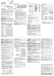
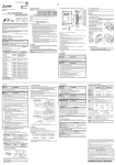
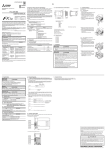
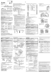
1.2 External Dimensions and Part Names
90(3.55")
How to obtain manuals
For the necessary product manuals or documents, consult with the Mitsubishi Electric
dealer from who you purchased this product.
How to obtain FX Configurator-EN
The parameter setting software, FX Configurator-EN is not supplied with this product.
Consult with the Mitsubishi Electric dealer from who you purchased this product
Remark
EN61131-2:2003
Compliance with all relevant aspects of the
Programmable controllers
standard.
- Equipment requirements and • Radiated Emissions
tests
• Mains Terminal Voltage Emissions
• RF immunity
• Fast Transients
• ESD
• Conducted
• Surge
• Power magnetic fields
[1] Direct mounting hole:2 holes of φ4.5
Used when ENET is directly mounted.
Not used when DIN rail is mounted.
[2] DIN rail mounting groove
[3] DIN rail mounting hook
[4] Extension cable
[5] RUN LED
[6] INIT. LED
[7] 100M LED
[8] SD LED
[9] RD LED
[10] ERR. LED
[11] COM.ERR. LED
[12] Not available
[13] POWER LED
[14] C1 to C8 LEDs
[15] RJ45 modular jack
[16] Terminal block for power supply (24V DC) (M3 terminal block screw)
[17] Extension connector
Indications of LEDs
FX3U-ENET is an Ethernet unit for the FX3U/FX3UC Series (Ver.2.21 or later) PLC that
is compliant with 100BASE-TX/10BASE-T and has the features as follows.
1) Data and programs within the PLC can be sent and received via Ethernet by using
GX Developer Ver.8.25B or later.
2) Communication between PLCs or with a general Ethernet device is possible by
fixed buffer communication. (TCP/IP or UDP/IP)
3) Users can develop custom software to communicate with the PLC by using MC
(MELSEC Communication) protocol (A-compatible 1E frame subset, for details,
refer to user's manual). (TCP/IP or UDP/IP)
4) E-mail can be sent and received. (SMTP or POP3 protocol)
5) The FX3U -ENET parameters can be set easily using FX Configurator-EN.
6) The diagnostic functions of FX Configurator-EN enables easy diagnostics and
troubleshooting of the FX3U-ENET.
1.1 Incorporated Items
Indication ({: Off, ●: On)
● : Normal operation
{ : Operation error
INIT.
● : Normal completion of initial processing
{ : Initial processing not yet completed
100M
● : 100Mbps
{ : 10Mbps not connected
SD
● : Sending data
{ : Not sending data
RD
● : Receiving data
{ : Not receiving data
ERR
● : Setting error*
{ : No setting error
COM ERR ● : Communication error
{ : Normal communication
POWER
● : Power on
{ : Power off
C1 to C8
● : Channel is open
{ : Channel is closed
LED
RUN
RUN
INIT.
100M
SD
RD
ERR.
COM.ERR.
POWER
C1
C2
C3
C4
C5
C6
C7
C8
Notes for compliance to EMC regulation.
The (FX3U-ENET) must be installed in a shielded metal control panel.
For more details please contact your local Mitsubishi Electric sales site.
1. Outline
• Use this product in the environment within the general specifications described
in this manual.
Never use the product in areas with excessive dust, oily smoke, conductive
dusts, corrosive gas (salt air, Cl2, H2S, SO 2, or NO2), flammable gas, vibration
or impacts, or expose it to high temperature, condensation, or rain and wind.
Doing so may cause electrical shock, fire, malfunctions, or damage or critical
deterioration to the product.
• When tightening the terminal screws, stay within the specified torque range.
When tightened insufficiently, short-circuit or failure may occur. When tightened
too much, the screws or the unit may be damaged, causing the unit disposal,
short-circuit, or failure.
• Do not touch the conductive part or electric parts of this unit directly.
Doing so may cause failure or malfunctions.
• Install the unit on a flat surface.
If the mounting surface is rough, undue force will be applied to the PC board,
thereby causing nonconformities.
2.1 Mounting
The FX3U-ENET can be mounted directly using screws or on a DIN rail (DIN46227).
2.1.1 Direct Mounting
The FX3U-ENET can be mounted with M4 screws by using the direct mounting
holes.
A space of 1 to 2 mm (0.04” to 0.08”) between each unit is necessary.
→ For the mounting hole pitch information, refer to Section 1.2
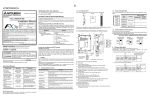
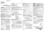
2.1.2 DIN Rail Mounting
The FX3U-ENET can be mounted on a DIN rail (DIN46227, 35mm width).
1) Fit the upper edge of the DIN rail mounting
groove (fig. A) onto the DIN rail.
2) Push the unit onto the DIN rail.
1)
A
*The ERR LED illuminates in the following cases:
- When an operational error occurs in the PLC CPU
- When an error is found in the Ethernet unit (H/W error)
2)
Pin Configuration
The pin configuration of ENET RJ45 type modular jack (for category 5 or category 3)
is as follows:
8
1
Pin No.
Signal
Direction
Contents
1
TD+
Out
+ side of sending data
2
TD−
Out
− side of sending data
3
RD+
In
+ side of receiving data
4
Not used
-
5
Not used
-
Product
Ethernet unit for the FX3U/FX 3UC Series PLC
6
RD−
In
7
Not used
-
Included items
Installation Manual (this manual)
Dust sheet
Label for indication of special function unit/block number
8
Not used
-
− side of receiving data
2.1.3 Procedure for connecting with the FX3U Series PLC
When connecting to an FX3U :
1)
Before connections, turn off the power to the PLC.
1) Remove the extension device connector cover
of the main unit.
2) Fold and insert the extension cable in the
corresponding connector as shown to the right.
2)
3) Reattach the extension device connector cover
on the main unit.
3)
When connecting to an FX3UC:
When connecting the FX 3U-ENET, either
the FX 3UC-1PS-5V or FX 2NC-CNV-IF is
required.
Connector cover
(A)
FX3UC-1PS-5V
1) The connector cover (A) of the
FX3UC -1PS-5V is removed as
shown in the figure to the right.
The FX2NC-CNV-IF does not have a
connector cover.
2) Connect the extension cable as
shown to the right.
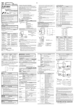
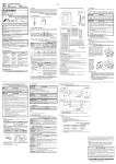
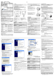
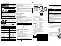
4. System configuration
DISPOSAL
PRECAUTIONS
System configuration example
• Please contact a certified electronic waste disposal company for the
environmentally safe recycling and disposal of your device.
TRANSPORT AND
STORAGE PRECAUTIONS
Extension cable on
the right side
• The product is a precision instrument. During transportation, avoid any impacts.
Failure to do so may cause failures in the product.
• After transportation, verify the operations of the product.
For the general specifications, refer to the manual of FX Series PLC.
FX3UC-1PS-5V or
FX2NC-CNV-IF
2.2 Wire end treatment
The solderless terminal size depends on the terminal screw size and wiring
method.
- Use solderless terminals of the following size.
- Tighten the terminals to a torque of 0.5 N•m to 0.8 N•m.
When using M3 terminal screw
For the main unit, input/output powered extension unit/block and special function
unit/block
• When one wire is connected to one terminal
Terminal Crimp
screw
terminal
φ 3.2(0.13")
6.2mm(0.24")
or less
6.2mm(0.24")
or less
φ 3.2(0.13")
• When two wires are connected to one terminal
φ 3.2(0.13")
6.2mm(0.24")
or less
6.3mm(0.25")
or more
Item
General
specification
Transmission
specifications
Terminal
Terminal
screw
Crimp
terminal
φ 3.2(0.13")
6.2mm(0.24")
or less
PC
- GX Developer
- FX Configurator-EN
Terminal
6.3mm(0.25")
or more
3. Specification
STARTUP AND
MAINTENANCE
PRECAUTIONS
• Do not touch any terminals or connector while the PLC's power is on.
Doing so may cause electrical shock or malfunctions.
• Before cleaning or retightening screws, externally cut off all phases of the
power supply.
Failure to do so may cause malfunction or failure of this unit.
When the screws are tightened insufficiently, they may fall out and cause a
short-circuit or malfunction. When tightened too much, the screws or the unit
may be damaged, resulting in short-circuit, or malfunction.
• When controlling the PLC (especially when changing data, the program or
changing the operating conditions) during operation, ensure that it is safe to
do so.
STARTUP AND
MAINTENANCE
PRECAUTIONS
• Do not disassemble or modify the unit.
Doing so may cause fire, equipment failures, or malfunctions.
• The unit case is made of resin. If dropped or subjected to strong impact, the
unit may be damaged.
• When this unit is installed or removed from the panel, make sure to externally
cut off all phases of the power supply. Failure to do so may cause malfunction
or failure of this unit.
0 to 55°C (32 to 131°F) when operating and -20
to 75°C (-4 to 167°F) when stored
Dielectric withstand
voltage
500 V AC for one minute
Insulation resistance
5MΩ or more by 500V DC
Baud rate
100Mbps
Communication
method
Full-duplex/Half-duplex
Transmission method
Base band
Max i mum length of
segment
100m(328’2”)*1
Maximum number of
nodes/connections
Cascade connection 2 Cascade connection 4
stages max.
stages max.
Conforming to
JEM-1021
Between all
terminals and the
ground terminal
10Mbps
Number of available
Sending/ files opened
simultaneously
receiving data
capacity Fixed buffer
specifiAttached file
cations
E-mail
Body text
1023 word × 8
Number of I/O occupied points
8 points
Power
supply
specifications
24V DC
+20%, -15%, ripple (p-p) less than 5%
Current consumption
FX3U/
FX3UC
FX3UENET
FX3U/
FX3UC
FX3UENET
FX3U/
FX3UC
FX3UENET
Specifications
Ambient temperature
Power supply
HUB
8 connections
(Available connections for sequence program)
2048 word × 1*2
256 word × 1*2
240mA
External dimensions
90(H) × 55(W) × 87(D) [mm]
3.55"(H) × 2.17"(W) × 3.43"(D) [inches]
MASS (Weight)
0.3kg(0.66lbs)
Number of connectable units to
1
the main unit
*1 Length between a hub and a node
*2 Refer to the FX3U-ENET User's Manual of e-mail sending/receiving function
specifications.
PLC
Ethernet unit
LAN cable
FX3U Series PLC
FX3UC Series PLC
+ FX2NC-CNV-IF FX3U-ENET
Shielded twisted-pair cable
10BASE-T : Category 5e, 5 or 3
100BASE-T : Category 5e or 5
FX3UC Series PLC
+ FX3UC-1PS-5V
FX Configurator-EN
Ver.1.00 or later
GX Developer applicable version
Ver.8.25B or later
FX3U/FX3UC PLC applicable version
Ver.2.21 or later
5. Wiring
WIRING
PRECAUTIONS
• Make sure to cut off all phases of the power supply externally before attempting
wiring work.
Failure to do so may cause electric shock or damage to the product.
WIRING
PRECAUTIONS
• Before wiring the unit, confirm that the rated voltage and terminal allocation of
the unit are correct. An incorrect voltage supply and/or incorrect wiring may
cause fire, malfunction, or failure.
• Perform class D grounding (grounding resistance: 100Ω or less) to the
grounding terminal on the main unit.
Do not use common grounding with heavy electrical systems.
• Prevent cutting or wiring debris from entering the main unit. Failure to do so
cause fire, malfunctions, or failures.
• Place a label that warns of electrical shock (417-IEC-5036) on the enclosure of
the final equipment.
PLC
Other
equipment
Independent grounding
Best condition
PLC
Other
equipment
PLC
Shared grounding
Good condition
Other
equipment
Common grounding
Not allowed
Wiring and power supply wiring between PLC and FX3U -ENET
Example usage of FX3U
Externally supplied
for ENET
24+
24-
D Grounding
(100 Ω or less)
24+
24FX3U
ENET
LAN
HUB
Ethernet
modular jack
(RJ-45)
This manual confers no industrial property rights or any rights of any other kind,
nor does it confer any patent licenses. Mitsubishi Electric Corporation cannot be
held responsible for any problems involving industrial property rights which may
occur as a result of using the contents noted in this manual.
Warranty
Mitsubishi will not be held liable for damage caused by factors found not to be
the cause of Mitsubishi; opportunity loss or lost profits caused by faults in the
Mitsubishi products; damage, secondary damage, accident compensation
caused by special factors unpredictable by Mitsubishi; damages to products
other than Mitsubishi products; and to other duties.
For safe use
• This product has been manufactured as a general-purpose part for general
industries, and has not been designed or manufactured to be incorporated in
a device or system used in purposes related to human life.
• Before using the product for special purposes such as nuclear power, electric
power, aerospace, medicine or passenger movement vehicles, consult with
Mitsubishi Electric.
• This product has been manufactured under strict quality control. However
when installing the product where major accidents or losses could occur if the
product fails, install appropriate backup or failsafe functions in the system.
HEAD OFFICE : TOKYO BUILDING, 2-7-3 MARUNOUCHI, CHIYODA-KU, TOKYO 100-8310,
JAPAN
HIMEJI WORKS : 840, CHIYODA CHO, HIMEJI, JAPAN