1
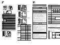
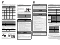
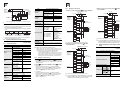
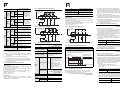
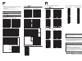
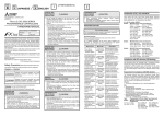
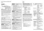
JY997D50501C Side B Side A JAPANESE Side B ENGLISH FX3UC (D, DS, DSS) SERIES PROGRAMMABLE CONTROLLERS HARDWARE MANUAL Manual Number JY997D50501 Revision C Date April 2015 This manual describes the part names, dimensions, mounting, cabling and specifications for the product. This manual is extracted from FX3UC (D,DS,DSS) Series User's Manual - Hardware Edition. Refer to FX3UC Series User's Manual - Hardware Edition details. Before use, read this manual and manuals of relevant products fully to acquire proficiency in the handling and operating the product. Make sure to learn all the product information, safety information, and precautions. And, store this manual in a safe place so that it can be taken out and read whenever necessary. Always forward it to the end user. Registration The company name and the product name to be described in this manual are the registered trademarks or trademarks of each company. Effective April 2015 Specifications are subject to change without notice. © 2013 Mitsubishi Electric Corporation Safety Precaution (Read these precautions before use.) This manual classifies the safety precautions into two categories: and . Indicates that incorrect handling may cause hazardous conditions, resulting in death or severe injury. Indicates that incorrect handling may cause hazardous conditions, resulting in medium or slight personal injury or physical damage. Depending on the circumstances, procedures indicated by may also cause severe injury. It is important to follow all precautions for personal safety. STARTUP AND MAINTENANCE PRECAUTIONS TRANSPORTATION AND STORAGE PRECAUTIONS Do not touch any terminal while the PLC's power is on. Doing so may cause electric shock or malfunctions. Before cleaning or retightening terminals, cut off all phases of the power supply externally. Failure to do so may cause electric shock. Before modifying or disrupting the program in operation or running the PLC, carefully read through this manual and the associated manuals and ensure the safety of the operation. An operation error may damage the machinery or cause accidents. Do not change the program in the PLC from two or more peripheral equipment devices at the same time. (i.e. from a programming tool and a GOT) Doing so may cause destruction or malfunction of the PLC program. Use the battery for memory backup correctly in FX3UC Series User's Manual - Hardware Edition. - Use the battery only for the specified purpose. - Connect the battery correctly. - Do not charge, disassemble, heat, put in fire, short-circuit, connect reversely, weld, swallow or burn the battery, or apply excessive forces (vibration, impact, drop, etc.) to the battery. - Do not store or use the battery at high temperatures or expose to direct sunlight. - Do not expose to water, bring near fire or touch liquid leakage or other contents directly. - Incorrect handling of the battery may cause heat excessive generation, bursting, ignition, liquid leakage or deformation, and lead to injury, fire or failures and malfunctions of facilities and other equipment. Before transporting the PLC, turn on the power to the PLC to check that the BAT LED is off, and check the battery life. If the PLC is transported with the BAT LED on or the battery exhausted, the battery-backed data may be unstable during transportation. The PLC is a precision instrument. During transportation, avoid impacts larger than those specified in Section 2.1. Failure to do so may cause failures in the PLC. After transportation, verify the operations of the PLC. When transporting lithium batteries, follow required transportation regulations. (For details of the regulated products, refer to FX3UC Series User's Manual - Hardware Edition.) Turn off the power to the PLC before attaching or detaching the memory cassette. If the memory cassette is attached or detached while the PLC's power is on, the data in the memory may be destroyed, or the memory cassette may be damaged. Do not disassemble or modify the PLC. Doing so may cause fire, equipment failures, or malfunctions. For repair, contact your local Mitsubishi Electric representative. Turn off the power to the PLC before connecting or disconnecting any extension cable. Failure to do so may cause equipment failures or malfunctions. Turn off the power to the PLC before attaching or detaching the following devices. Failure to do so may cause equipment failures or malfunctions. - Peripheral devices, extension units/blocks, connector conversion adapter, extension power supply units, special adapters, and FX Series terminal blocks. - Battery and memory cassettes DISPOSAL PRECAUTIONS Please contact a certified electronic waste disposal company for the environmentally safe recycling and disposal of your device. When disposing of batteries, separate them from other waste according to local regulations. (For details of the Battery Directive in EU countries, refer to FX3UC Series User's Manual - Hardware Edition.) Manual name How to obtain manuals For the necessary product manuals or documents, consult with your local Mitsubishi Electric representative. Associated manuals FX3UC (D, DS, DSS) Series PLC (main unit) comes with this document (hardware manual). For a detailed explanation of the FX3UC Series hardware and information on instructions for PLC programming and special extension unit/block, refer to the relevant documents. Manual No. Description FX3UC Series User's Manual - Hardware Edition Explains FX3UC Series JY997D28701 PLC specification details MODEL CODE: for I/O, wiring, installation, 09R519 and maintenance. FX3S/FX3G/FX3GC/ FX3U/FX3UC Series Programming Manual - Basic & Applied Instruction Edition Describes PLC JY997D16601 programming for basic/ MODEL CODE: applied instructions STL/ 09R517 SFC programming and devices. MELSEC-Q/L/F SH-080782 Structured MODEL CODE: Programming Manual 13JW06 (Fundamentals) Programming methods, specifications, functions, etc. required to create structured programs. FXCPU Structured JY997D26001 Devices, parameters, etc. Programming Manual MODEL CODE: provided in structured [Device & Common] 09R925 projects of GX Works2. FXCPU Structured JY997D34701 Sequence instructions Programming Manual MODEL CODE: provided in structured [Basic & Applied 09R926 projects of GX Works2. Instruction] FXCPU Structured JY997D34801 Application functions Programming Manual MODEL CODE: provided in structured [Application 09R927 projects of GX Works2. Functions] FX Series User’s Manual - Data Communication Edition Description JY997D16701 MODEL CODE: 09R619 Describes specifications for analog control and programming methods for FX3S/FX3G/FX3GC/FX3U/ FX3UC Series PLC. FX3S/FX3G/FX3GC/ FX3U/FX3UC Series User's Manual - Positioning Control Edition Explains the specifications JY997D16801 for positioning control of MODEL CODE: FX3S/FX3G/FX3GC/FX3U/ 09R620 FX3UC Series and programming procedures Certification of UL, cUL standards FX3UC series main units, FX3U series special adapter, extension power supply unit and FX2N/FX2NC series input/output extension blocks supporting UL, cUL standards are as follows: Associated manuals Manual name STARTUP AND MAINTENANCE PRECAUTIONS Manual No. FX3S/FX3G/FX3GC/ FX3U/FX3UC Series User's Manual - Analog Control Edition Explains N:N link, parallel JY997D16901 link, computer link, no MODEL CODE: protocol communication 09R715 by RS instructions/FX2N232IF. UL, cUL file number: E95239 Models: MELSEC FX3U(C) series manufactured FX3UC-MT/D FX3UC-MT/DSS Where indicates: 16, 32, 64, 96 FX3UC-16MR/D-T FX3UC-16MR/DS-T FX3U-232ADP(-MB) FX3U-485ADP(-MB) FX3U-CF-ADP FX3U-ENET-ADP FX3U-4AD-ADP FX3U-4DA-ADP FX3U-3A-ADP FX3U-4AD-PT-ADP FX3U-4AD-PTW-ADP FX3U-4AD-PNK-ADP FX3U-4AD-TC-ADP FX3UC-1PS-5V Models: MELSEC FX2NC series manufactured FX2NC-32EX(-DS) FX2NC-16EX(-DS) FX2NC-16EYT(-DSS) FX2NC-32EYT(-DSS) FX2NC-16EX-T(-DS) FX2NC-16EYR-T(-DS) Models: MELSEC FX2N series manufactured FX2N-8EX-ES/UL FX2N-8ER-ES/UL FX2N-8EYR-ES/UL FX2N-8EYR-S-ES/UL FX2N-8EYT-ESS/UL FX2N-8EX-UA1/UL FX2N-16EYR-ES/UL FX2N-16EX-ES/UL FX2N-16EYT-ESS/UL FX2N-16EYS Compliance with EC directive (CE Marking) This document does not guarantee that a mechanical system including this product will comply with the following standards. Compliance to EMC directive and LVD directive of the entire mechanical system should be checked by the user / manufacturer. For more details please contact the local Mitsubishi Electric sales site. Requirement for Compliance with EMC directive The following products have shown compliance through direct testing (of the identified standards below) and design analysis (through the creation of a technical construction file) to the European Directive for Electromagnetic Compatibility (2004/108/EC) when used as directed by the appropriate documentation. Attention This product is designed for use in industrial applications. Note Authorized Representative in the European Community: Mitsubishi Electric Europe B.V. Gothaer Str. 8, 40880 Ratingen, Germany Type: Models: Programmable Controller (Open Type Equipment) MELSEC FX3U(C) series and FX2NC series manufactured from May 1st, 2005 FX3U-FLROM-16 FX3U-FLROM-64L from June 1st, 2005 FX3U-232ADP FX3U-485ADP FX3U-4AD-ADP FX3U-4DA-ADP FX3U-4AD-PT-ADP FX3U-4AD-TC-ADP FX3U-FLROM-64 from April 1st, 2007 FX3U-232ADP-MB FX3U-485ADP-MB from September 1st, 2007 FX3UC-MT/D FX3UC-MT/DSS Where indicates: 16, 32, 64, 96 from October 1st, 2007 FX3UC-1PS-5V FX2NC-EX FX2NC-EYT FX2NC-EX-DS FX2NC-EYT-DSS Where indicates: 16, 32 FX2NC-16EX-T FX2NC-16EX-T-DS from December 1st, 2007 FX3U-4AD-PTW-ADP FX3U-4AD-PNK-ADP from June 1st, 2009 FX3U-3A-ADP FX3U-CF-ADP from September 1st, 2010 FX3UC-16MR/D-T FX3UC-16MR/DS-T from May 1st, 2011 FX3U-FLROM-1M from February 1st, 2012 FX3U-ENET-ADP Standard Remark EN61131-2: 2007 Programmable controllers - Equipment requirements and tests Compliance with all relevant aspects of the standard. EMI Radiated Emission Conducted Emission EMS Radiated electromagnetic field Fast transient burst Electrostatic discharge High-energy surge Voltage drops and interruptions Conducted RF Power frequency magnetic field Models: MELSEC FX2NC series manufactured from March 1st, 1999 FX2NC-EX-DS FX2NC-EYT-DSS Where indicates: 16, 32 from August 1st, 1999 FX2NC-16EX-T-DS FX2NC-16EYR-T-DS from October 1st, 2007 FX2NC-EX FX2NC-EYT Where indicates: 16, 32 FX2NC-16EX-T FX2NC-16EYR-T Standard Models: MELSEC FX2N series manufactured from July 1st, 1997 FX2N-16EX-ES/UL FX2N-16EYR-ES/UL FX2N-16EYT-ESS/UL FX2N-8EX-ES/UL from August 1st, 2005 FX2N-8ER-ES/UL FX2N-8EYR-ES/UL FX2N-8EYT-ESS/UL from September 1st, 2010 FX2N-8EYR-S-ES/UL For the products above, PLC’s manufactured before March 31st, 2002 are compliant with EN50081-2 (EN610006-4) and EN50082-2 only. PLC’s manufactured from April 1st, 2002 to April 30th, 2006 are compliant with EN50081-2 (EN61000-6-4) and EN61131-2: 1994 +A11: 1996 +A12: 2000 PLC’s manufactured after May 1st, 2006 are compliant with EN61131-2: 2007 Standard Compliance with all relevant aspects of the standard. Emission-Enclosure port Emission-Low voltage AC mains port Emission-Telecommunications/ network port EN50082-2: 1995 Electromagnetic compatibility - Generic immunity standard Industrial environment Compliance with all relevant aspects of the standard. RF immunity Fast Transients ESD Conducted Power magnetic fields EN61131-2: 1994 /A11: 1996 /A12: 2000 Programmable controllers - Equipment requirements and tests Compliance with all relevant aspects of the standard. Radiated electromagnetic field Fast transient burst Electrostatic discharge Damped oscillatory wave EN61131-2: 2007 Programmable controllers - Equipment requirements and tests Compliance with all relevant aspects of the standard. EMI Radiated Emission Conducted Emission EMS Radiated electromagnetic field Fast transient burst Electrostatic discharge High-energy surge Voltage drops and interruptions Conducted RF Power frequency magnetic field Remark EN61000-6-4: 2007 - Generic emission standard Industrial environment EN50081-2: 1993 Electromagnetic compatibility Compliance with all relevant aspects of the standard. Emission-Enclosure port Emission-Low voltage AC mains port Emission-Telecommunications/ network port EN61000-6-2: 2005 - Generic immunity standard Industrial environment Compliance with all relevant aspects of the standard. Radio-frequency electromagnetic field. Amplitude modulated Fast transients Electrostatic discharge Surges Voltage dips Voltage interruptions Radio-frequency common mode Power-frequency magnetic field Remark EN61000-6-4: 2007 - Generic emission standard Industrial environment EN50081-2:1993 Electromagnetic compatibility Requirement for Compliance with LVD directive The following products have shown compliance through direct testing (of the identified standards below) and design analysis (through the creation of a technical construction file) to the European Directive for Low Voltage (2006/95/EC) when used as directed by the appropriate documentation. Type: Programmable Controller (Open Type Equipment) Models: MELSEC FX3UC series manufactured from September 1st, 2010 FX3UC-16MR/D-T FX3UC-16MR/DS-T Standard EN61131-2: 2007 Programmable controllers - Equipment requirements and tests Remark The equipment has been assessed as a component for fitting in a suitable enclosure which meets the requirements of EN61131-2: 2007 Models: MELSEC FX2NC series manufactured from August 1st, 1999 FX2NC-16EYR-T-DS from October 1st, 2007 FX2NC-16EYR-T Standard IEC1010-1: 1990 /A1: 1992 BSEN61010-1: 1993 (*) Safety requirements for electrical equipment for measurement, control, and laboratory use - General requirements ( *) Remark The equipment has been assessed as a component for fitting in a suitable enclosure which meets the requirements of IEC 1010-1: 1990 +A1: 1992 Compliance to BSEN61010-1 is claimed through virtue of direct compliance to IEC1010-1 and Amendment 1. Models: MELSEC FX2N series manufactured from July 1st, 1997 FX2N-16EYR-ES/UL from August 1st, 2005 FX2N-8ER-ES/UL FX2N-8EYR-ES/UL from September 1st, 2010 FX2N-8EYR-S-ES/UL For the products above, PLC’s manufactured before March 31st, 2002 are compliant with IEC1010-1 PLC’s manufactured from April 1st, 2002 to April 30th, 2006 are compliant with EN61131-2: 1994 +A11: 1996 +A12: 2000 PLC’s manufactured after May 1st, 2006 are compliant with EN61131-2: 2007 Standard Remark IEC1010-1: 1990 /A1: 1992 Safety requirements for electrical equipment for measurement, control, and laboratory use - General requirements The equipment has been assessed as a component for fitting in a suitable enclosure which meets the requirements of IEC 1010-1: 1990 +A1: 1992 EN61131-2: 1994 : 2007 /A12: 2000 /A11: 1996 Programmable controllers - Equipment requirements and tests The equipment has been assessed as a component for fitting in a suitable enclosure which meets the requirements of EN61131-2: 1994 +A11: 1996 +A12: 2000 : 2007 Caution for Compliance with EC directive Installation in Enclosure Programmable logic controllers are open-type devices that must be installed and used within conductive control boxes. Please use the FX3UC (D, DS, DSS) Series programmable logic controllers while installed in conductive shielded control boxes. Please secure the control box lid to the control box (for conduction). Installation within a control box greatly affects the safety of the system and aids in shielding noise from the programmable logic controller. Caution for Analog Products in use The analog special adapters have been found to be compliant to the European standards in the aforesaid manual and directive. However, for the very best performance from what are in fact delicate measuring and controlled output device Mitsubishi Electric would like to make the following points; As analog devices are sensitive by nature, their use should be considered carefully. For users of proprietary cables (integral with sensors or actuators), these users should follow the manufacturers’ installation requirements. Mitsubishi Electric recommends that shielded cables be used. If no other EMC protection is provided, then users may experience temporary loss of accuracy between +10 %/-10 % in very heavy industrial areas. However, Mitsubishi Electric suggests that when adequate EMC precautions are followed with general good EMC practice for the users complete control system. - Sensitive analog cables should not be laid next to or bound with high voltage cabling. Where possible, users should run analog cables separately. - Good cable shielding should be used. When grounding the shield - ensure that no loops are accidentally created. - When reading analog values, EMC induced errors can be smoothed out by averaging the readings. This can be achieved either through functions on the analog special adapter/block or through the user’s program in the FX3UC Series PLC main unit. Incorporated Items Verify that the following product and items are included in the package. Included Items Main units Product FX3UC-MT/D FX3UC-16MR/D-T 1 unit FX2NC-100MPCB [1 m (3’ 3"), three wire] 1 cable FX2NC-100BPCB [1 m (3’ 3"), two wire] 1 cable Manuals [Japanese/English] 1 manual Product FX3UC-MT/DSS FX3UC-16MR/DS-T 1 unit FX2NC-100MPCB [1 m (3’ 3"), three wire] 1 cable Manuals [Japanese/English] 1 manual Input/output extension blocks FX2NC-EX FX2NC-16EX-T Product 1 unit FX2NC-10BPCB1 [0.1 m (3.93"), double-ended] FX2NC-EX-DS FX2NC-16EX-T-DS FX2NC-EYT Product FX2NC-EYT-DSS FX2NC-16EYR-T FX2NC-16EYR-T-DS 1. 1.1 1 cable 1 unit Outline Part names [2] Front panel [12] [6] Under side [5] [11] [14] [7] [9] [2] [4] [8] [2] [10] [15] [6] [6] [4] Left side Main units (Terminal block type) Right side [6] [2] Unit: mm(inches) [1] [3] [4] [6] [2] [5] Display LED [4] INSTALLATION PRECAUTIONS 15 (0.60") W 74(2.92") No. Name Memory cassette dummy cover [2] Special adapter connecting hooks [3] Special adapter connector cover [4] DIN rail mounting hooks [5] POW LED On while power is on the PLC. RUN LED On while the PLC is running. BAT LED Lights when the battery voltage drops. ERR LED [6] W (13) (0.52") 74(2.91") FX2NC input/output extension blocks (Terminal block type) Unit: mm(inches) Flashing when a program error occurs. 90 [1] 90(3.54") Unit: mm(inches) Lights when a CPU error occurs. FX2NC/FX3UC Extension block connecting hooks [7] Input LED [8] Output LED [9] Input connector (-T indicates terminal block type) W 15 (0.60") [11] Peripheral device connecting connector (RS-422) Type [12] RUN/STOP switch [13] FX2NC/FX3UC Extension block connecting connector cover [14] Power connector for main unit Main units (Connector type) [15] Battery cover 1.2 External dimensions/weight Main units (Connector type) 90(3.54") Unit: mm(inches) W (13) (0.52") 74(2.91") Main units (Terminal block type) Input/output extension blocks (Connector type) Input/output extension blocks (Terminal block type) Model name INSTALLATION PRECAUTIONS Use the product within the generic environment specifications described in section 2.1 of this manual. Never use the product in areas with excessive dust, oily smoke, conductive dusts, corrosive gas (salt air, Cl2, H2S, SO2 or NO2), flammable gas, vibration or impacts, or expose it to high temperature, condensation, or rain and wind. If the product is used in such conditions, electric shock, fire, malfunctions, deterioration or damage may occur. Do not touch the conductive parts of the product directly. Doing so may cause device failures or malfunctions. Install the product securely using a DIN rail or mounting screws. Install the product on a flat surface. If the mounting surface is rough, undue force will be applied to the PC board, thereby causing nonconformities. When drilling screw holes or wiring, make sure that cutting and wiring debris do not enter the ventilation slits. Failure to do so may cause fire, equipment failures or malfunctions. W: mm MASS (Weight): (inches) kg (lbs) FX3UC-16MT/D(SS) 34.0 (1.34) Approx. 0.2 (0.44) FX3UC-32MT/D(SS) 34.0 (1.34) Approx. 0.2 (0.44) FX3UC-64MT/D(SS) 59.7 (2.36) Approx. 0.3 (0.66) FX3UC-96MT/D(SS) 85.4 (3.37) Approx. 0.35 (0.77) FX3UC-16MR/D(S)-T 34.0 (1.34) Approx. 0.25 (0.55) FX2NC-16EX(-DS) 14.6 (0.57) Approx. 0.15 (0.33) FX2NC-32EX(-DS) 26.2 (1.03) Approx. 0.2 (0.44) FX2NC-16EYT(-DSS) 14.6 (0.57) Approx. 0.15 (0.33) FX2NC-32EYT(-DSS) 26.2 (1.03) Approx. 0.2 (0.44) FX2NC-16EX-T(-DS) 20.2 (0.57) Approx. 0.15 (0.33) FX2NC-16EYR-T(-DS) 24.2 (0.95) Approx. 0.2 (0.44) Generic specifications [Main unit] Item Be sure to remove the dust proof sheet from the PLC's ventilation port when installation work is completed. Failure to do so may cause fire, equipment failures or malfunctions. Connect the extension cables, peripheral device cables, input/ output cables and battery connecting cable securely to their designated connectors. Loose connections may cause malfunctions. Turn off the power to the PLC before attaching or detaching the following devices. Failure to do so may cause device failures or malfunctions. - Peripheral devices, extension units/blocks, connector conversion adapter, extension power supply units, special adapters, and FX Series terminal blocks - Battery and memory cassettes Notes When a dust proof sheet is supplied with an extension unit/ block, keep the sheet applied to the ventilation slits during installation and wiring work. To prevent temperature rise, do not install the PLC on a floor, a ceiling or a vertical surface. Install it horizontally on a wall as shown in section 2.2. Keep a space of 50 mm (1.97”) or more between the unit main body and another device or structure (section 2.2 part A). Install the unit as far away as possible from high-voltage lines, highvoltage devices and power equipment. Specification Ambient 0 to 55 C (32 to 131 F) when operating and -25 to temperature 75 C (-13 to 167 F) when stored Vibration resistance (*1) 5 to 95 %RH (no condensation) when operating Frequency (Hz) When 10 to 57 installed 57 to on DIN 150 rail Acceleration (m/s2) Half amplitude (mm) - 0.035 4.9 - Sweep Count for X, Y, Z: 10 times (80 min. in each direction) Shock resistanc (*1) (147 m/s2 Acceleration, Action time: 11 ms, 3 times by half-sine pulse in each direction X, Y, and Z) Noise resistance By noise simulator at noise voltage of 1,000 Vp-p, noise width of 1 s, rise time of 1ns and period of 30 to 100 Hz Dielectric withstand voltage 500 V AC for one minute Insulation resistance 5 M or more by 500 V DC megger Grounding Class D grounding (grounding resistance: 100 or less) <Common grounding with a heavy electrical system is not allowed.> (*2) Between batch of all terminals and ground terminal Working Free from corrosive or flammable gas and excessive atmosphere conductive dusts Working altitude INSTALLATION PRECAUTIONS 74(2.91") [10] Output connector (-T indicates terminal block type) 2.1 Ambient humidity Make sure to cut off all phases of the power supply externally before attempting installation or wiring work. Failure to do so may cause electric shock or damage to the product. FX2NC input/output extension blocks (Connector type) Green Green Red Red General specifications and Installation For more details, refer to the FX3UC Series User's Manual Hardware Edition 90(3.54") [13] 2. <2000 m (*3) (*1) The criterion is shown in IEC61131-2. (*2) For common grounding, refer to section 3.2. (*3) The PLC cannot be used at a pressure higher than the atmospheric pressure to avoid damage. 2.2 Installation Location Install the PLC in an environment conforming to the generic specifications (section 2.1), installation precautions and notes. For more details, refer to FX3UC Series User's Manual Hardware Edition. Installation location in enclosure Space in enclosure Extension devices can be connected on the left and right sides of the PLC main unit. If you intend to add extension devices in the future, keep extra space on the left and right sides open. 3) Align the upper side of the DIN rail mounting groove with the DIN rail ( in the figure on the right). 2.5 2 Configuration without extension cable FX2NC-16EX FX2NC-16EYT FX3UC Main unit A A A 4) While pressing the main unit onto the DIN rail, lock the DIN rail mounting hooks as shown in the figure below B . B A A ≥ 50 mm (1.97") Configuration with extension cable FX2N-10PG FX2NC-16EX A A FX2N-CNV-BC A 2.3.2 2) Disconnect all connected cables including the power cable and I/O cable. 3 Other equipment 2 4) Lever the screwdriver slightly toward direction , to pull out the DIN rail mounting hooks, allowing them to come off the DIN rail. A ≥ 50 mm A (1.97") Procedures for installing to and detaching from DIN rail Installing methods 6) Push the DIN rail mounting hooks as shown in the figure on the right . 2) Push the DIN rail mounting hooks of all connected units/blocks as shown in the figure on the right A . 1 A 1 2) Input/output cables (available from Mitsubishi) Input/output cables with attached connectors are available. FX-16E500CAB-S 5m (16’4”) 2) Pinch the power cable connector "a" and disconnect it in the direction of the arrow (see figure on the right). FX-16E150CAB 1.5 m (4’11”) FX-16E300CAB 3m (9’10”) FX-16E500CAB 5m (16’4”) FX-16E150CAB-R 1.5 m (4’11”) FX-16E300CAB-R 3m (9’10”) FX-16E500CAB-R 5m (16’4”) FX-A32E150CAB 1.5 m (4’11”) FX-A32E300CAB 3m (9’10”) FX-A32E500CAB 5m (16’4”) 4 Type Model A Power cable for main unit FX2NC100MP CB B Input power cable for FX2NC series input FX2NCextension blocks and 100BP FX2NC/FX3UC series CB special function blocks 1m (3’ 3") C Input power crossover cable for FX2NC FX2NCseries input extension 10BPC blocks and FX2NC/ B1 FX3UC series special function blocks FX2NC-EX, FX2NC-16EX-T, 0.1 m and (3.93") FX2NC/FX3UC series special function blocks Connection of power supply connector Length Cable supplied with Application 1m (3’ 3") FX3UC-MT/ D(SS), FX3UC-16MR/ D(S)-T FX3UC-MT/D, FX3UC-16MR/D-T The crossover cable (type "C") can skip up to 4 16-point output blocks to connect units. If more blocks should be skipped to supply power to an input block, use cable type "B". Output Y 1) Compliant connectors (commercially available connectors) Use a 20-pin (1-key) socket connector conforming to MIL-C83503. Confirm in advance that the connectors do not interfere with other parts including connector covers. 1) Turn the power supply OFF. Power Cable types "A" and "B" are supplied with the main unit, while type "C" is supplied with the FX2NC-EX, FX2NC-16EX-T, and FX2NC/FX3UC series special function blocks. Use the dedicated built-in power connector to supply power to the main unit. The power should be supplied to the main unit, FX2NC Series I/O extension blocks and FX2NC/FX3UC Series special extension blocks. Some (FX2NC-EX(-T)) of FX2NC Series I/O extension blocks require power cable types B and C shown on the right, while others (FX2NC-EX(-T)-DS) do not require them. For details, refer to FX3UC Series User's Manual - Hardware Edition. When connecting two or more extension blocks which require power cables "B" and "C" shown on the right, perform crossover wiring between the extension blocks using two (upper and lower) power connectors. Input X Length a Press here 5) Remove the main unit from the DIN rail ( in the figure on the right). 2.4 1) Turn the power supply OFF. 1 Connection to input/output connector The input/output connectors of the Main units (Connector type) conform to MIL-C-83503. Refer to Chapter 4 for the I/O connector pin arrangement. Model names Removal of the power cable 3) Insert a flathead screwdriver to the DIN rail mounting hook ( in the figure on the right). The main unit can be installed on a DIN46277 rail [35 mm (1.38”) wide]. For detail, refer to the following manual. Refer to FX3UC Series User's Manual - Hardware Edition. 2.3.1 Removal methods 1) Turn the power supply OFF. FX0N-65EC FX0N-30EC A Other equipment 2.3 FX2NC-CNV-IF FX3UC Main unit FX3U-4AD-ADP Other equipment A A The figure below shows the pin numbers of the power connectors. Input extension block Extension block Output extension block Main unit 1 (Red) 1 (Red) Input extension block 2 (Black) 2 (Black) 3 Ground (Green) Two power connectors of each extension block are connected in parallel inside the block. A Accordingly, there is no Red discrimination between the entrance Black side and the exit side of the power Green C supply. Either (upper or lower) Red Ground connector can be connected. B Black At shipment from the factory, a resin cover is attached to the lower connector. Connect the upper connector first. Remove the resin cover from the lower connector when performing crossover wiring for the later block. (In case of the FX2NC-EX(-T)-DS, removal of the connector cover is unnecessary.) Main unit Description Shape Single wire (Wire color: red) General-purpose input/output cable PLC side: A 20-pin connector Cables for connecting the FX Series terminal block with input/ output connectors. For terminal block connection, refer to FX3UC Series User's Manual Hardware Edition. Cables for connecting the A Series Model A6TBXY36 connector/ terminal block conversion unit and input/output connector type Flat cables (with tube) A 20-pin connector at both ends Round multicore cables A 20-pin connector at both ends Flat cables (with tube) PLC side: Two 20pin connectors in 16-point units. Terminal block side: A dedicated connector One common terminal covers 32 input/output terminals. 3) Connectors for user-made input/output cables (available from Mitsubishi) Users should provide electric wires and a pressure bonding tool. Model name and composition of input/output connector Applicable electric wire (UL-1061 are recommended) and tool Details of part (made by DDK Ltd.) Pressure bonding tool (made by DDK Ltd.) Our model name Solderless 10connector piece FRC2set A020-30S FX2C-I/OCON for flat cable Housing HU-200S2FX2C-I/O5001 CON-S piece Solderless for bulk wire set contact HU-411S Housing HU-200S2FX2C-I/O5001 CON-SA piece Solderless for bulk wire set contact HU-411SA Electric wire size AWG28 (0.1 mm2) 1.27 pitch, 20-core 357J-4674D: Main body 357J-4664N: Attachment AWG22 (0.3 mm2) 357J-5538 AWG20 (0.5 mm2) Wire size Single wire 0.3 mm2 to 0.5 mm2 (AWG22 to 20) Double wire 0.3 mm2 (AWG22)2 2) Termination Strip the coating of strand wire and twist the cable core before connecting it, or strip the coating of single wire before connecting it. An alternative connection is to use a ferrule with insulating sleeve. <Reference> Phoenix Contact Model AI 0.5-8WH Caulking tool CRIMPFOX 6 (*1) (or CRIMPFOX 6T-F (*2)) (*1) Old model name: CRIMPFOX ZA 3 (*2) Old model name: CRIMPFOX UD 6 Stranded wire/solid wire Termination of cable end Bar terminal with insulating sleeve Insulating sleeve Contact area (Crimp area) 9 mm (0.36") 8 mm (0.32") 2.6 mm (0.11") With straight tip 0.4 mm (0.02") 2.5 mm (0.1") Note: If the diameter of screwdriver grip is too small, tightening torque will not be able to be achieved. To achieve the appropriate tightening torque shown in the table above, use the following screwdriver or an appropriate replacement (grip diameter approximately 25 mm (0.98”)). <Reference> 3. 1) Applicable cable Manufacturer Notes Model SZS 0.42.5 357J-13963 Cable Type Tool To tighten terminals, use a purchased small-sized screwdriver whose head is straight and is not widened as shown in the right figure. Phoenix Contact Connection to input/output terminal block 2.6.1 Tightening Torque Tighten the terminals to a torque of 0.22 to 0.25 N•m. Do not tighten terminal screws with a torque outside the abovementioned range. Failure to do so may cause equipment failures or malfunctions. Manufacturer 4) Certified connectors (commercially available connectors) Connectors made by DDK Ltd. shown in item 3). 2.6 2.6.2 14 mm(0.56") When using a stick terminal with an insulating sleeve, choose a wire with proper cable sheath referring to the above outside dimensions, otherwise the wire cannot be inserted easily. Power supply/input/output specifications and examples of external wiring DESIGN PRECAUTIONS Make sure to have the following safety circuits outside of the PLC to ensure safe system operation even during external power supply problems or PLC failure. Otherwise, malfunctions may cause serious accidents. 1) Most importantly, have the following: an emergency stop circuit, a protection circuit, an interlock circuit for opposite movements (such as normal vs. reverse rotation), and an interlock circuit (to prevent damage to the equipment at the upper and lower positioning limits). 2) Note that when the PLC CPU detects an error, such as a watchdog timer error, during self-diagnosis, all outputs are turned off. Also, when an error that cannot be detected by the PLC CPU occurs in an input/output control block, output control may be disabled. External circuits and mechanisms should be designed to ensure safe machinery operation in such a case. 3) Note that when an error occurs in a relay, triac or transistor output device, the output could be held either on or off. For output signals that may lead to serious accidents, external circuits and mechanisms should be designed to ensure safe machinery operation in such a case. DESIGN PRECAUTIONS Do not bundle the control line together with or lay it close to the main circuit or power line. As a guideline, lay the control line at least 100 mm (3.94") or more away from the main circuit or power line. Noise may cause malfunctions. Install module so that excessive force will not be applied to peripheral device connectors, power connectors or input/output connectors. Failure to do so may result in wire damage/breakage or PLC failure. Simultaneously turn on and off the power supplies of the main unit and extension devices. Even if the power supply causes an instantaneous power failure for 5 ms or less, the PLC can continue to operate. If a long-time power failure or an abnormal voltage drop occurs, the PLC stops, and output is turned off. When the power supply is restored, it will automatically restart (when the RUN input is on). WIRING PRECAUTIONS 3.1 Power supply specifications and example of external wiring For more details, refer to FX3UC Series User's Manual - Hardware Edition. 3.1.1 Power supply specifications The specifications for the power supply of the main unit are shown in the following table. Item Specification 24 V DC +20 % -15 % (*1) Supply voltage Make sure to cut off all phases of the power supply externally before attempting installation or wiring work. Failure to do so may cause electric shock or damage to the product. WIRING PRECAUTIONS Ripple Voltage (p-p)5 % or less Operation can be continued Allowable instantaneous power upon occurrence of an failure time instantaneous power failure for 5 ms or less. Power fuse 125 V 3.15 A Rush current Connect the DC power supply wiring to the dedicated terminals described in this manual. If an AC power supply is connected to a DC input/output terminal or DC power supply terminal, the PLC will burn out. Do not wire vacant terminals externally. Doing so may damage the product. Perform class D grounding (grounding resistance: 100 or less) to the grounding terminal on the main unit. Do not use common grounding with heavy electrical systems (refer to section 3.2). When drilling screw holes or wiring, make sure cutting or wire debris does not enter the ventilation slits. Failure to do so may cause fire, equipment failures or malfunctions. Make sure to properly wire to the terminal block (European type) in accordance with the following precautions. Failure to do so may cause electric shock, equipment failures, a short-circuit, wire breakage, malfunctions, or damage to the product. - The disposal size of the cable end should follow the dimensions described in the manual. - Tightening torque should follow the specifications in the manual. - Twist the end of strand wire and make sure that there are no loose wires. - Do not solder-plate the electric wire ends. - Do not connect more than the specified number of wires or electric wires of unspecified size. - Affix the electric wires so that neither the terminal block nor the connected parts are directly stressed. Notes Input/output wiring 50 to 100 m (164’1” to 328’1”) long will cause almost no problems of noise, but, generally, the wiring length should be less than 20 m (65’7”) to ensure the safety. Extension cables are easily affected by noise. Lay the cables at a distance of at least 30 to 50 mm (1.19” to 1.97”) away from the PLC output and other power lines. Power consumption (*1) 5 V DC built-in power supply(*2) 30 A max.0.5 ms/24 V DC FX3UC-16MT/D(SS) 6W FX3UC-16MR/D(S)-T FX3UC-32MT/D(SS) 8W FX3UC-64MT/D(SS) 11 W FX3UC-96MT/D(SS) 14 W FX3UC-16MT/D(SS) 600 mA FX3UC-16MR/D(S)-T FX3UC-32MT/D(SS) 560 mA FX3UC-64MT/D(SS) 480 mA FX3UC-96MT/D(SS) 400 mA (*1) Input/output extension blocks and special function units/blocks ar e no t c o n t ai n ed in p o we r c o n s u mp t io n . F o r p o we r consumption of the FX2NC input/output extension blocks, refer to the following table. Refer to the FX3UC Series User's Manual - Hardware Edition. For the power consumed by the special function units/blocks, refer to the appropriate manuals. Model names Power consumption FX2NC-16EX-T(-DS) 2.2 W FX2NC-16EX(-DS) 2.2 W FX2NC-32EX(-DS) 4.2 W FX2NC-16EYR-T(-DS) 2.2 W FX2NC-16EYT(-DSS) 0.35 W FX2NC-32EYT(-DSS) 0.7 W (*2) Cannot be used to supply power to an external destination. This power is supplied to input/output extension blocks, special extension blocks and special adapters only. 3.1.2 Example of external wiring (power type) Supply 24 V DC power to the main unit and FX2NC-EX(-T) using the dedicated connector. For the details of wiring work, refer to Section 2.4. For the power supply wiring of the FX2NC input extension blocks, refer to the Subsection 3.3.3. Use a 24 V DC +20 % -15 % DC power supply whose ripple (p-p) is within 5 %. The allowable range of the 24 V DC power supply may be narrower when special function units/blocks are connected. For more details, refer to the FX3UC Series User's Manual Hardware Edition. Item 24 V DC +20 % -15 % Breaker,Circuit protector,Fuse etc. Fuse PL Power MC on Emergency stop Class D grounding Refer to section 3.2 for details. Input specification (24 V DC) Input signal current 6 mA/24 V DC X006, X007 7 mA/24 V DC X010 or more (*1) 5 mA/24 V DC Input extension blocks ON input sensitivity current PLC X000 to X005 X000 to X005 3.5 mA or more X006, X007 4.5 mA or more X010 or more (*1) 3.5 mA or more Input extension blocks Power supply for loads connected to PLC output terminals 3.2 Grounding Ground the PLC as stated below. Input OFF current 1.5 mA or less Input response time Approx. 10 ms (*2) Ground the PLC independently if possible. If it cannot be grounded independently, ground it jointly as shown below. Other equipment PLC Other equipment PLC Other equipment Input signal form Independent grounding Shared grounding Common grounding (Best condition) (Good condition) (Not allowed) Position the grounding point as close to the PLC as possible to decrease the length of the ground wire. 3.3 Input specifications and external wiring For more details, refer to the FX3UC Series User's Manual Hardware Edition. 3.3.1 Input specifications Item Input specification (24 V DC) FX3UC-16MT/D(SS) FX3UC-16MR/D(S)-T 8 points FX3UC-32MT/D(SS) 16 points Number of input FX3UC-64MT/D(SS) points FX3UC-96MT/D(SS) 32 points Input connecting type Input form Input signal voltage Input impedance 48 points FX2NC-16EX(-DS) 16 points FX2NC-32EX(-DS) 32 points FX2NC-16EX-T(-DS) 16 points FX3UC-MT/D(SS) FX2NC-EX(-DS) connector FX3UC-16MR/D(S)-T FX2NC-16EX-T(-DS) Terminal block FX3UC-MT/D FX3UC-16MR/D-T FX2NC-EX FX2NC-16EX-T FX3UC-MT/DSS FX3UC-16MR/D(S)-T FX2NC-EX-DS FX2NC-16EX-T-DS Sink Sink/Source 24 V DC +20 % -15 % Ripple Voltage (p-p)5 % or less X000 to X005 3.9 k X006, X007 3.3 k X010 or more (*1) Input extension blocks 4.3 k Example of input wiring 1. Examples of input wiring (FX3UC-MT/D, FX3UC-16MR/D-T) FX3UC-MT/D FX3UC-16MR/D-T FX2NC-EX FX2NC-16EX-T No-voltage contact input NPN open collector transistor FX3UC-MT/DSS FX3UC-16MR/D(S)-T FX2NC-EX-DS FX2NC-16EX-T-DS Sink input: No-voltage contact input NPN open collector transistor Source input: No-voltage contact input PNP open collector transistor Input circuit insulation Photocoupler insulation Input operation display LED on panel turns ON when photocoupler is driven. 24 V DC Handling of input terminal Class D grounding (*1) COM0 X000 X000 Class D grounding (*1) (*2) (*2) Three wire sensor NPN X001 X002 FX2NCEX(-T)-DS COM0 FX2NCEX(-T) COM0 X0 COM COM (*1) The grounding resistance should be 100 or less. X0 (*2) In FX3UC-64MT/DSS or FX3UC-96MT/DSS units, the COM0, (*1) The grounding resistance should be 100 or less. COM1 and COM2 terminals are not connected internally. Wire the COM0, COM1 and COM2 terminals respectively. 2. Examples of sink input wiring (FX3UC-MT/DSS, FX3UC-16MR/DS-T) 3.4 Breaker, Circuit protector, Fuse, etc. 24 V DC Output specifications and example of external wiring For more details, refer to the FX3UC Series User's Manual Hardware Edition. Fuse 3.4.1 Transistor output specifications FX3UCMT/DSS FX3UC16MR/DS-T Output specification (Transistor) Item COM0 X002 - Three wire sensor NPN X002 2) FX3UC-MT/DSS, FX3UC-16MR/DS-T, FX2NC-EX(-T)-DS source input Inputs turn ON when the 24 V DC terminal and COM terminal or COM terminal are connected, and the input terminal and 24 V DC + terminal are electrically connected with a novoltage contact or PNP open collector transistor. Where indicates:0 to 2 COM0 COM COM0 - Fuse FX3UCMT/DSS FX3UC16MR/DS-T 1) FX3UC-MT/D, FX3UC-16MR/D-T, FX2NC-EX(-T) Inputs turn ON when the input terminal and COM terminal are electrically connected with a no-voltage contact or NPN open collector transistor sink input Inputs turn ON when the 24 V DC + terminal and COM terminal or COM terminal are connected, and the input terminal and 24 V DC terminal are electrically connected with a novoltage contact or NPN open collector transistor. 24 V DC Fuse X001 (*2) 000 to X017 use adjustable digital filter values. 3.3.2 Breaker, Circuit protector, Fuse, etc. FX3UCMT/D FX3UC16MR/D-T (*1) Does not apply to FX3UC-16M. When setting the input filter for X000 to X005 to 5 s or capturing pulses of a 50 to 100 kHz response frequency with a high speed counter, wire the terminals as stated below. - The wiring length should be 5 m (16’4”) or less. - Connect a bleeder resistor of 1.5 k (1 W or more) to the input terminal, so that the sum of the load current of the open collector transistor output on the connected device and the input current of the main body is 20 mA or more. 3. Examples of source input wiring (FX3UC-MT/DSS, FX3UC-16MR/DS-T) Breaker, Circuit protector, Fuse, etc. COM Perform class D grounding. (Grounding resistance: 100 or less) PLC 3.3.3 ( *2) Class D grounding (*1) ( *2) Number of output points X000 X001 FX3UC-16MT/D(SS) 8 points FX3UC-32MT/D(SS) 16 points FX3UC-64MT/D(SS) 32 points FX3UC-96MT/D(SS) 48 points FX2NC-16EYT(-DSS) 16 points Three wire sensor NPN FX2NC-32EYT(-DSS) 32 points Output connecting type FX2NCEX(-T)-DS COM0 COM0 X0 (*1) The grounding resistance should be 100 or less. (*2) In FX3UC-64MT/DSS or FX3UC-96MT/DSS units, the COM0, COM1 and COM2 terminals are not connected internally. Wire the COM0, COM1 and COM2 terminals respectively. Output form connector FX3UC-MT/ D FX2NC-EYT Sink FX3UC-MT/ DSS FX2NC-EYT -DSS Source External power supply 5 to 30V DC Output specification (Transistor) Item Max. load Y000 to 0.3 A/point Y003 Main Resist units Y004 or ance 0.1 A/point more load FX2NC-EYT 0.1 A/point (-DSS) Main Induct units ive load Y000 to 7.2 W/point Make sure that the Y003 (24 V DC) total load of 16 inductive load Y004 or 2.4 W/point points is 38.4 W/ more (24 V DC) 24 V DC or less. FX2NC-EYT (-DSS) Open circuit leakage current Main OFF units ON ON OFF Main units Example of transistor output wiring FX3UC-MT/D FX2NC-EYT Y001 Load Emergency stop 24 V DC Y000 Y002 Load Mechanical insulation Output operation display LED on panel lights when power is applied to relay coil. Load Fuse 3.4.6 FX3UC-MT/DSS FX2NC-EYT-DSS +V0 +V0 FX3UC-16MR/ D(S)-T FX2NC-16EYR-T (-DS) Y000 Y001 Load Emergency stop (*1) Y002 Y000 to 5 s or less/10 mA or more (5 to 24 V DC) (*2) Y002 Load Emergency stop 100 V AC Y003 or 0.2 ms or less/100 mA or more (at 24 V DC) (*3) more Output circuit insulation Photocoupler insulation Output operation display LED on panel turns ON when photocoupler is driven. (*1) When the two COM terminal are connected outside the PLC, resistance load is 1.6 A or less. (*2) When using an instruction related to pulse train output or positioning, make sure to set the load current to 10 to 100 mA (5 to 24 V DC). 3.4.4 Item Number of output points External power supply 30 V DC or less or 240 V AC or less (250 V AC or less when the unit does not comply with CE, UL or cUL standards) Output current The ON voltage of the output transistor is approx. 1.5 V. When driving a semiconductor element, carefully check the input voltage characteristics of the applied element. Max. load Load Cautions in input and output wiring Notes 80 VA For the product life of relay contacts, refer to the FX3UC Series User's Manual - Hardware Edition. 3.5.1 5 V DC, 2 mA (reference value) Open circuit leakage current Response time Load - OFFON Approx. 10 ms ONOFF Approx. 10 ms 2) In the case of input device with built-in parallel resistance: Use a device with a parallel resistance of 15 kor more. When the resistance is less than 15 k, connect a bleeder resistor. 3) In the case of 2-wire proximity switch: Use a two-wire proximity switch whose leakage current is 1.5 mA or less when the switch is off. When the current is 1.5 mA or more, connect a bleeder resistor. 3.5.2 When only the main unit is used (without extension units/blocks) applicable 20 % 40 °C 45 °C 55 °C Ambient temperature Instructions for input devices The input current of this PLC is 5 to 7 mA/24 V DC. Use input devices applicable to this minute current. If switches for larger current are being used, contact failure may occur. For more details, refer to FX3UC Series User's Manual - Hardware Edition. Cautions on transistor output wiring For more details, refer to FX3UC Series User's Manual - Hardware Edition. 1) Protection circuit for load short-circuits A short-circuit at a load connected to an output terminal could cause burnout at the output element or the PC board. To prevent this, a protection fuse should be included at the output. Use a load power supply capacity that is two times or more the total rated capacity of the fuses connected to the load circuit. 2) Contact protection circuit for inductive loads When an inductive load is connected, connect a diode (for commutation) in parallel with the load as necessary. The diode (for commutation) must comply with the following specifications. Reverse voltage 5 to 10 times of the load voltage Forward current Load current or more 3) Interlock Loads, such as contactors for normal and reverse rotations, that must not be turned on simultaneously should have an interlock in the PLC program and an external interlock. 3.5.3 The derating curve below shows the simultaneous ON ratio of available PLC inputs or outputs with respect to the ambient temperature. Use the PLC within the simultaneous input or output ON ratio range shown in the figure. Derating curve When extension units/ simultaneous ON ratio blocks are connected Supply voltage: 24 V DC 80 % 65 % 60 % Min. load Load one. 3.5 When using one COM terminal, make sure that the total load current of 4 or 8 resistance load points is 4 A or less. 2A Resistance load When connecting two /point COM terminals outside the PLC, make sure that the total load current of 8 resistance load points is 8 A or less. Inductive load Y002 Fuse 8 points FX2NC-16EYR-T(-DS) 16 points Terminal block Handling of transistor output circuit Y001 Output specification (Relay) FX3UC-16MR/D(S)-T Output connecting type For example, under a load of 24 V DC 40 mA, the response time is approx. 0.3 ms. When response performance is required under light loads, provide a dummy resistor to increase the load current. Y000 (*1) As for the number of COM1 terminals, FX3UC-16MR/D(S)-T is Relay output specifications For more details, refer to the FX3UC Series User's Manual Hardware Edition. (*3) The transistor OFF time is longer under lighter loads. Output terminal: The main unit and FX2NC input/output extension block have 16 transistor output points per common. Two COM or +V terminals connected to each other inside the PLC are provided for outputs. Connect two COM or +V terminals outside the PLC so that the load applied to each COM or +V terminal is smaller. Where indicates: 1 to 3 Where indicates: 0 to 2 (*1) Load 24 V DC Fuse 1) In the case of input devices with built-in series diodes: The voltage drop of the series diode should be approx. 4 V or less. When lead switches with a series LED are used, up to two switches can be connected in series. Also make sure that the input current is over the input-sensing level while the switches are ON. (ex.) Lead switches with a series LED Example of relay output wiring COM1 COM1 0.2 ms or less/100 mA or more (at 24 V DC) 0.2 ms or less/100 mA or more (at 24 V DC) Handling of relay output circuit Output terminal: Main units, FX2NC input/output extension blocks have 4 or 8 relay output points per common. Two COM terminals connected to each other inside the FX2NC16EYR-T(-DS) are provided for outputs. Connect two COM terminals outside the PLC so that the load applied to each COM terminal is smaller. Where indicates:1 or 2 2. Examples of source output wiring 0.1 mA or less/30 V DC Output specification (Relay) Output circuit insulation 3.4.5 COM1 COM1 Y003 or 0.2 ms or less/100 mA or more (at 24 V DC) (*3) more FX2NC-EYT (-DSS) 3.4.2 Item 1. Examples of sink output wiring 2.4 W/point (24 V DC) Y000 to 5 s or less/10 mA or more (5 to 24 V DC) (*2) Y002 FX2NC-EYT (-DSS) Resp onse time Make sure that the total load current of 8 resistance load points is 0.8 A (*1) or less. 3.4.3 Cautions on relay output wiring For more details, refer to FX3UC Series User's Manual - Hardware Edition. 1) Protection circuit for load short-circuits A short-circuit at a load connected to an output terminal could cause burnout at the output element or the PC board. To prevent this, a protection fuse should be included at the output. 2) Protection circuit of contact when inductive load is used An internal protection circuit for the relays is not provided for the relay output circuit. It is recommended to use inductive loads with built-in protection circuits. When using loads without built-in protection circuits, insert an external contact protection circuit, etc. to reduce noise and extend the product life. a) DC circuit Connect a diode in parallel with the load. U s e a d io d e (f o r c o mmu t a ti on ) h av i ng t he f oll ow in g specifications. Reverse voltage 5 to 10 times of the load voltage Forward current Load current or more b) AC circuit Connect the surge absorber (combined CR components such as a surge killer and spark killer, etc.) parallel to the load. Select the rated voltage of the surge absorber suitable to the output used. Refer to the table below for other specification Electrostatic capacity Approx. 0.1 F Resistance value Approx. 100 to 200 Notch IN X0 X10 X1 X11 X2 X12 X3 X13 X4 X14 X5 X15 X6 X16 X7 X17 COM0 COM0 IN X20 X30 X21 X31 X22 X32 X23 X33 X24 X34 X25 X35 X26 X36 X27 X37 COM1 COM1 OUT Y20 Y30 Y21 Y31 Y22 Y32 Y23 Y33 Y24 Y34 Y25 Y35 Y26 Y36 Y27 Y37 +V1 +V1 Notch IN X0 X0 X1 X1 X2 X2 X3 X3 X4 X4 X5 X5 X6 X6 X7 X7 COM0 COM0 Lower Lower Upper Notch FX2NC-32EX-DS Notch IN X0 X0 X1 X1 X2 X2 X3 X3 X4 X4 X5 X5 X6 X6 X7 X7 COM0 COM0 IN X0 X0 X1 X1 X2 X2 X3 X3 X4 X4 X5 X5 X6 X6 X7 X7 COM1 COM1 Notch X0 X1 X2 X3 X4 X5 X6 X7 COM COM Y0 Y1 Y2 Y3 Y4 Y5 Y6 Y7 COM2 COM2 Notch IN X0 X10 X1 X11 X2 X12 X3 X13 X4 X14 X5 X15 X6 X16 X7 X17 COM0 COM0 OUT Y0 Y10 Y1 Y11 Y2 Y12 Y3 Y13 Y4 Y14 Y5 Y15 Y6 Y16 Y7 Y17 +V0 +V0 IN X20 X30 X21 X31 X22 X32 X23 X33 X24 X34 X25 X35 X26 X36 X27 X37 COM1 COM1 OUT Y0 Y10 Y1 Y11 Y2 Y12 Y3 Y13 Y4 Y14 Y5 Y15 Y6 Y16 Y7 Y17 COM1 COM1 IN X20 X30 X21 X31 X22 X32 X23 X33 X24 X34 X25 X35 X26 X36 X27 X37 COM COM OUT Y20 Y30 Y21 Y31 Y22 Y32 Y23 Y33 Y24 Y34 Y25 Y35 Y26 Y36 Y27 Y37 COM2 COM2 IN X40 X50 X41 X51 X42 X52 X43 X53 X44 X54 X45 X55 X46 X56 X47 X57 COM2 COM2 Notch IN OUT X40 X50 Y40 Y50 X41 X51 Y41 Y51 X42 X52 Y42 Y52 X43 X53 Y43 Y53 X44 X54 Y44 Y54 X45 X55 Y45 Y55 X46 X56 Y46 Y56 X47 X57 Y47 Y57 COM COM COM3 COM3 OUT Y20 Y30 Y21 Y31 Y22 Y32 Y23 Y33 Y24 Y34 Y25 Y35 Y26 Y36 Y27 Y37 +V1 +V1 4.1.3 Notch FX3UC-16MR/D(S)-T IN X0 X1 X2 X3 COM OUT Y0 Y1 Y2 Y3 COM1 X4 X5 X6 X7 COM Y4 Y5 Y6 Y7 COM2 4.2.2 FX2NC-EYT(-DSS) FX2NC-16EYT Notch OUT Y40 Y50 Y41 Y51 Y42 Y52 Y43 Y53 Y44 Y54 Y45 Y55 Y46 Y56 Y47 Y57 +V2 +V2 Notch OUT Y0 Y0 Y1 Y1 Y2 Y2 Y3 Y3 Y4 Y4 Y5 Y5 Y6 Y6 Y7 Y7 COM1 COM1 FX2NC-32EYT Notch OUT Y0 Y0 Y1 Y1 Y2 Y2 Y3 Y3 Y4 Y4 Y5 Y5 Y6 Y6 Y7 Y7 COM1 COM1 OUT Y0 Y0 Y1 Y1 Y2 Y2 Y3 Y3 Y4 Y4 Y5 Y5 Y6 Y6 Y7 Y7 COM2 COM2 FX2NC-16EYT-DSS FX2NC-32EYT-DSS OUT Y0 Y0 Y1 Y1 Y2 Y2 Y3 Y3 Y4 Y4 Y5 Y5 Y6 Y6 Y7 Y7 +V0 +V0 OUT Y0 Y0 Y1 Y1 Y2 Y2 Y3 Y3 Y4 Y4 Y5 Y5 Y6 Y6 Y7 Y7 +V0 +V0 Notch OUT Y0 Y0 Y1 Y1 Y2 Y2 Y3 Y3 Y4 Y4 Y5 Y5 Y6 Y6 Y7 Y7 +V1 +V1 Upper OUT Y20 Y30 Y21 Y31 Y22 Y32 Y23 Y33 Y24 Y34 Y25 Y35 Y26 Y36 Y27 Y37 COM2 COM2 Notch Upper IN X20 X30 X21 X31 X22 X32 X23 X33 X24 X34 X25 X35 X26 X36 X27 X37 COM COM Lower OUT Y0 Y10 Y1 Y11 Y2 Y12 Y3 Y13 Y4 Y14 Y5 Y15 Y6 Y16 Y7 Y17 COM1 COM1 FX3UC-96MT/D IN X0 X10 X1 X11 X2 X12 X3 X13 X4 X14 X5 X15 X6 X16 X7 X17 COM COM Upper FX2NC-16EX-DS OUT Y0 Y10 Y1 Y11 Y2 Y12 Y3 Y13 Y4 Y14 Y5 Y15 Y6 Y16 Y7 Y17 +V0 +V0 X0 X0 X1 X1 X2 X2 X3 X3 X4 X4 X5 X5 X6 X6 X7 X7 COM COM OUT Y0 Y1 Y2 Y3 Y4 Y5 Y6 Y7 COM1 COM1 FX3UC-96MT/DSS FX3UC-64MT/D IN X0 X10 X1 X11 X2 X12 X3 X13 X4 X14 X5 X15 X6 X16 X7 X17 COM COM FX3UC-64MT/DSS X0 X0 X1 X1 X2 X2 X3 X3 X4 X4 X5 X5 X6 X6 X7 X7 COM COM FX2NC-16EYR-T(-DS) Lower OUT Y0 Y10 Y1 Y11 Y2 Y12 Y3 Y13 Y4 Y14 Y5 Y15 Y6 Y16 Y7 Y17 COM1 COM1 IN IN X0 X1 X2 X3 X4 X5 X6 X7 COM COM Upper Notch IN X0 X10 X1 X11 X2 X12 X3 X13 X4 X14 X5 X15 X6 X16 X7 X17 COM COM Lower X0 – X1 – X2 – X3 – X4 – X5 – X6 – X7 – COM COM OUT Y0 – Y1 – Y2 – Y3 – Y4 – Y5 – Y6 – Y7 – COM1 COM1 Upper IN Notch IN Upper FX3UC-MT/D The I/O wiring is different in the FX3UC-MT/DSS. Refer to Sections 3.3 and 3.4 for the details. FX3UC-16MT/D FX3UC-32MT/D X0 X0 X1 X1 X2 X2 X3 X3 X4 X4 X5 X5 X6 X6 X7 X7 COM COM FX2NC-32EX Upper 4.1.1 IN FX2NC-16EX-T(-DS), FX2NC-16EYR-T(-DS) FX2NC-16EX-T(-DS) Upper Main units Notch Lower 4.1 Notch FX2NC-16EX Lower Terminal Layout OUT Y0 Y1 Y2 Y3 Y4 Y5 Y6 Y7 +V0 +V0 OUT Y0 Y10 Y1 Y11 Y2 Y12 Y3 Y13 Y4 Y14 Y5 Y15 Y6 Y16 Y7 Y17 +V0 +V0 4.2.3 FX2NC-EX(-DS) Upper IN X0 X1 X2 X3 X4 X5 X6 X7 COM0 COM0 IN X0 X10 X1 X11 X2 X12 X3 X13 X4 X14 X5 X15 X6 X16 X7 X17 COM0 COM0 FX2NC input/output extension blocks 4.2.1 Lower 4. 4.2 FX3UC-MT/DSS The I/O wiring is different in the FX3UC-MT/D. Refer to Sections 3.3 and 3.4 for the details. FX3UC-32MT/DSS FX3UC-16MT/DSS Lower 4) Common mode Use output contacts of the PLC in the common mode. 4.1.2 Lower 3) Interlock Loads, such as contactors for normal and reverse rotations, that must not be turned on simultaneously should have an interlock in the PLC program and an external interlock. Notch This manual confers no industrial property rights or any rights of any other kind, nor does it confer any patent licenses. Mitsubishi Electric Corporation cannot be held responsible for any problems involving industrial property rights which may occur as a result of using the contents noted in this manual. Warranty Mitsubishi will not be held liable for damage caused by factors found not to be the cause of Mitsubishi; opportunity loss or lost profits caused by faults in the Mitsubishi products; damage, secondary damage, accident compensation caused by special factors unpredictable by Mitsubishi; damages to products other than Mitsubishi products; and to other duties. For safe use This product has been manufactured as a general-purpose part for general industries, and has not been designed or manufactured to be incorporated in a device or system used in purposes related to human life. Before using the product for special purposes such as nuclear power, electric power, aerospace, medicine or passenger movement vehicles, consult with Mitsubishi Electric. This product has been manufactured under strict quality control. However when installing the product where major accidents or losses could occur if the product fails, install appropriate backup or failsafe functions in the system. HEAD OFFICE : TOKYO BUILDING, 2-7-3 MARUNOUCHI, CHIYODA-KU, TOKYO 100-8310, JAPAN