1
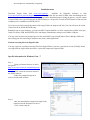
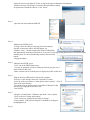
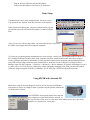
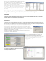
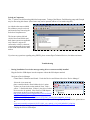
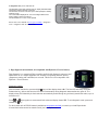
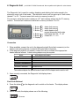
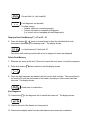
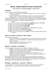
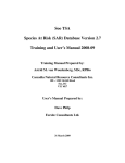
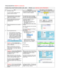
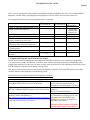
ESPAR DIAGNOSTIC TOOLS
01-2013
This is a review of diagnostic tools available from ESPAR to diagnose ESPAR heaters. The review includes EDiTH
diagnostic with ISO adapter, Digi-Diagnostic and Diagnostic Unit (also known as Error Retrieval Device).
The comparison table below lists most important features of the tools:
EDiTH+ISO adapter
Diagnostic Unit
22 1541 89 00 00
22 1545 89 00 00
Allows to read fault codes and unlock ECUs
Works with all current heaters
Does not require computer
Supports all current models of heaters
Reads advanced information from heaters
memory including run-time hours
Real-time diagnostic on running heater with
displaying status of internal components
Records and replays internal work processes
of running heater
High Altitude kit diagnostic
Required for warranty claims (reads hours
counter)
Digi-diagnostic
(discontinued)
+
Tested with
Airtronic and
Hydronic 4/5
+
-
+
+
+
+
+
+
+
+
-
-
+
-
-
+
-
-
+
+
-
yes
1. Computerized diagnostic with EDiTH and ISO adapter
In order to use advanced technology for heater diagnostic, ESPAR recommends to use computerized diagnostics
everywhere where possible, which allows you to have more detailed information needed for troubleshooting. With
computerized diagnostics you also have an option to easily share the recorded file with ESPAR specialist using E-mail.
EDiTH diagnostic is required for submitting warranty claims.
This chapter lists necessary adapters to perform EDiTH diagnostic and offers some extra information, but it is not a
complete manual for the diagnostic or troubleshooting itself.
Following items are needed for computerized diagnostics of heaters:
Tools
ISO adapter with USB-to-Serial adapter and VISTA/7
compatible EDiTH software p/n 22 1541 89 00 00
Prior to installing software, check if a
newer version or software update is
available for download (please see below)
Optional: Approved USB-to-Serial adapter with driver and
Needed if no serial port is available on
VISTA/7 compatible EDiTH software, p/n 22 1543 89 00 00
computer.
Does not include ISO adapter.
English and French versions are available
EDiTH software for Windows 98 and up, including
for download free of charge for use with
Windows VISTA and Windows 7*:
http://www.espar.com/tech_manuals/Diagnostic%20Software/ ISO adapter and with EDiTH Expert
Adapter (ECU testing unit, special tool
for heater repair centers).
*See note for VISTA and 7 users below
Current version of software is EDiTH
S4V1-F, please update your software
Adapter cables
(only one appropriate adapter is needed for each kind of installation)
Part #
Used with
Comment
22 1000 30 6900 B/D1/LCCompact
Y-cable. Works with all “Compact” heaters.
B/D3/LCCompact
20 2900 70 5046 Airtronic 2-4-5
Cable with two connectors. Use for installations with black
Hydronic M-II series
8-pin diagnostic connector (optional, otherwise remove
heaters 8-10-12 kW
spiral cable from ISO adapter and plug adapter directly to
diag. connector on harness)
22 1000 31 8600 Airtronic 2-4-5
Use if no diagnostic connectors installed.
20 2900 70 5028
Hydronic 4/5
Y-cable (not good for Cascadia 2009 w/round connector).
25 2786 70 0001
Hydronic 4/5
Freightliner Cascadia
2009
Hydronic 4/5 Z
Y-cable. Can be used only with Hydronic 5 with round 4 pin
connector, factory installed on Freightliner Cascadia trucks
in 2009. Not compatible with other heaters.
Y-cable with switchbox. May also be used for other
Hydronic 4/5 heaters except of Cascadia w/round connector.
3 pin to 6 pin adapter for 3 pin diagnostic connector
22 1000 31 6300
22 1000 33 7800
22 1000 33 3100
Hydronic-II
Hydronic 5E
Airtronic 2-4-5 and
Hydronic 4/5
20 2900 70 5031
D8LC
20 2900 70 5030
Hydronic 10
20 2900 70 5044
Hydronic 10/M
25 2800 70 1004
Hydronic M-II series
heaters 8-10-12 kW
Hydronic 16/24/30/35
22 1000 31 66 00
Use only when High Altitude Sensor p/n 22 1000 33 22 00 is
used (H-Kit). Do not use other adapters with H-Kit 22 1000
33 22 00 or remove sensor while use other adaptors (sensor
will not be tested in this case)
Y-cable with round connectors, not compatible with
Hydronic 10
Y-cable with round connectors, not compatible with D8LC
Y-cable with square connectors, not compatible with
Hydronic M-II series heaters
Y-cable. Use for installations without diagnostic connector.
Not compatible with earlier versions of Hydronic M.
H-cable
ISO adapter requires a computer with serial port (RS232). On computers with no serial port available, the included
Serial-to-USB adapter can be used. Use only USB 2.0 adapters as ISO adapter is not compatible with USB 1.1 serial-to
USB adapters. Recommended adapter is listed in the table above.
Diagnosis software EDiTH S4V0-F:
The latest diagnostic software EDiTH is available for download at ESPAR service portal, (www/espar.com/help/ =>
Diagnostic Software).
The software is available in the following languages: English, French, German, Italian, and Russian.
Currently version S4V0-F does not require installing of database update file.
The following modifications have been made at version S4V0-F:
- Several OEM/universal heater versions have been added into the data base:
-
Newer heaters are automatically recognized
Installation notes
Download Zipped folder from www.espar.com/help/
(subfolder for Diagnostic Software) or from
www.espar.com/tech_manuals/Diagnostic_Software The zip folder files are about 19.6MB. After downloading the file,
which may take some time and some browsers do not indicate download progress during the process, copy the content
of zipped folder into a special folder and run EDiTH Setup.exe. All previous versions of EDiTH must be removed from
computer prior to installation of EDiTH S4V0-F
If you do not previously unpack the content of the zipped folder, the program will ask if you wish to Extract all or Run.
Choose Extract all, then Run EDiTH setup.
Running Setup on some computers, you may have RS232 option disabled even if the computer has available serial port.
In this case choose USB, install EDiTH, run it and change communication setting to an available COM port.
You may check existence and assigned port # of the serial (RS232) port using Windows Device Manager. Make sure
that existing port does not belong to modem or not used by other applications.
Problem extracting files from Zipped Folder
You may experience a problem extracting files from Zipped Folder if you have expired trial version of WinZip. In this
case right click the zipped folder and choose “Open with compressed (zipped) folders”
Specific information for Windows Vista / 7
Step 1
-Using your internet browser of choice,
navigate to:
http://www.espar.com/tech_manuals/Diagnostic
Software/
-‘Click’ on the most current version of
the EDiTH software
-Follow the prompts that appear in
order to download the software
Step 2
-Once the download has completed, navigate to the
location where the download was saved.
-‘Click’ on the setup file
-follow the on screen prompts for EULA, saving location and confirmation of installation
-Windows Security will prompt several times during installation asking
for permission to install the software. Click ‘Allow’.
Step 3
-Open the start menu and launch EDiTH
Step 4
-Minimize the EDiTH screen
-If using a Serial to USB convertor plug it into the computer
now(don’t connect the cable to the ISO adapter yet)
-Windows Vista / 7 should recognize the Serial to USB adapter
and automatically install the required driver. If you receive a message stating that the driver was unsuccessfully
installed please see the troubleshooting section at the end of this
tutorial.
-Unplug the adapter.
Step 5
-Maximize the EDiTH screen
-‘Click’ Ok on the EDiTH flash screen
- You may be prompted to make a COM port selection, just pick one it
doesn’t matter at this point.
- Make a mental note as to which ports are displayed (COM3, in this case)
Step 6
-Plug the Serial to USB interface back into the computer.
-You may see the messages from step 4 again this is normal
-At the top of the screen there is a menu option called “Options”, ‘Click’ it.
Then select Serial Interface.
-You should now see another option for available COM ports (COM
8 in this case). Highlight it and select ‘OK’.
-Close EDiTH
Step 7
-Navigate to Control Panel > Hardware and sound > Power options
‘Click’ on the text “Change plan settings”.
-‘Click’ on the text “Change advanced power settings”
- Ensure that the ‘USB selective Suspend’ is disabled by clicking on
the highlighted text
Step 8
-Plug the Serial to USB cable into the ISO adapter
-Connect the ISO adapter to the Heater to be worked on
Basic Setup
Communications setup is fairly straightforward. Select the correct
Com port under the ‘Options’ menu bar and select ‘Serial interface’.
In the selection box that appears, select the communications port that
corresponds to the port in which the ISO adapter is connected (White
Box).
*Note: If you receive this message, either you selected the incorrect com port or
the USB to serial adapter has been configured improperly.
If you have any problems getting communications to work correctly, contact your system administrator to check if you
have available COM port on your system. Some computers may have installed software that unnecessary occupies
existing COM port and makes it unavailable for other programs. Another reason for having communication problem is
using USB-to Serial adapter without properly installed driver. In the last case the COM port is not listed in Device
Manager (right click My Computer => Properties => Hardware => Device Manager). If Serial-to-USB adapter is used, it
is usually easy to see if it is properly configured by simply unplugging replugging it into USB port and seeing which
COM port disappears/appears in the Device Manager. Use the same port # in EDiTH communication setup.
Using EDiTH with Airtronic D2
Much of the setup for using the diagnostic software will be the same for all heaters,
what follows is merely an example of what is possible using the popular Airtronic D2
(25 2069) model of heater.
Once EDiTH has been opened and the basic setup has
been completed, a heater model must be selected. In
the top left corner of the screen is a drop down menu called ‘heater’, hover the mouse
pointer over it and click on ‘select heater’.
The next popup screen will have three columns; on the left is
the selection for heater type (Airtronic, Hydronic 4/5,
Hydronic 10/ M, etc), the center shows the model number, and
on the right, the type of tests that are available.
Select the heater type that corresponds to the heater that you
are working on. Next, select the model number of the heater
(some popular heater types have the option for automatic
detection).
In our example of the Airtronic D2 model 25 2069) there are
three possible tests which may be performed; General data, functional test or switch on component.
General data
General data will give details such as number of hours, error codes and other details about the history of the heater’s
operation. Heater is not operated during a general data test.
Functional test
A functional test is generally the most widely used test. It allows the technician working on the heater to actually run
the heater while receiving and reviewing real-time data regarding the operation of the heater. Like the general data test
the functional test also allows for the error codes to be both displayed and cleared.
After selecting the correct model type, model number and selecting to start the
functional test you will receive a pop up similar to the one shown. The first two
options allow for control of setpoint either through the device control (Minicontroler,
Digicontroler, Thermostat, etc) or through
EDiTH via a text input. The ventilate option will just run the heater in vent or
circulate mode. Pick one and select ok.
There are two main screen that are of concern; the
Measured Values screen and the Graphic screen.
Any of the sensor values may be viewed on the graphic
screen by first clicking the checkbox beside the
displayed value.
The graphics screen allows for data to be viewed in chart
form in up to one hour increments.
Switch on Component
This 3rd option is useful for testing individual components. Testing of the Blower, Fuel Metering pump and Glowpin
may be done using this feature. (Note: heater may not be operated in Heat or Vent mode using this).
As with the other tests available
Error Memory may be retrieved
and cleared at any time using the
Switch on Component test.
The last two options (Switch
vehicle blower and Switch antitheft alarm system) are applicable
only if heater’s outputs are
connected to vehicle’s electrical
system and normally do not apply
to the North American after sales
market.
If you have any questions regarding using EDiTH, please contact Espar Technical Services, for further assistance
Troubleshooting
-
During Installation I received a message stating driver was unsuccessfully installed
Plug the Serial to USB adapter into the computer without the ISO adapter attached
Navigate to Device Manager
Control Panel > Hardware and Sound – Under the Devices and Printers title select “Device Manager”
-Select the view menu and
place a mark beside the ‘Show hidden devices’ option
-Is there any Icons in the section marked ‘Ports’ with a
yellow ‘!’ mark beside them. If there is, the driver for that
device needs to be updated. Most Serial to USB adapters
can operate on the driver located at this link:
http://www.prolific.com.tw/support/files/%5CIO%20Cabl
e%5CPL-2303%5CDrivers%20%20Generic%5CWindows%5Callinone%5CPL2303_Prolific_DriverInstaller_v110.zip
-If you are using the adapter that came with ISO adapter (sold through Espar) you can find the updated driver
at:
www.moxa.com/drivers/uport/u1130/V1.6/driv_win_uport1p_v1.6_build_09062913_whql.zip
-Follow the steps when prompted to install the driver.
-Unplug the Serial to USB adapter
-Reboot computer
-Plug Serial to USB adapter back into computer
-Navigate to Device manager again
-Ensure that the Computer has recognized the adapter and
does not have a error (error will be indicated by the
presence of a yellow ‘!’ beside the device)
-Continue with normal installation of EDiTH
-
When I plug the Serial to USB device into the computer I
don’t get another COM port.
-Did the driver install properly?
Navigate to Device Manager and ensure there are no “!” marks beside any of the items listed under
‘Ports (COM &LPT)’
-Follow the steps from the previous section to ensure driver for Serial to USB installed correctly.
-
I am having another problem that is not listed here.
-If the issue is in regards to the EDiTH software package
Please contact Espar’s Technical Dept at 1-800-387-4800
-If the issue is in regards to the Serial to USB adapter or Windows 7
Please contact your computer specialist or system administrator.
2. Diagnostic unit p/n 22 1545 89 00 00
The diagnostic unit is solely used to read out, display and delete faults
stored in the heater's electronic control box.
The electronic control box can store up to 5 faults (exception: auxiliary
heater D 3 W Z).
The current fault is displayed as " AF" and a 2-digit number and is
Always written in memory location F1.
The stored faults "F1" to "F5" can be queried.
Please refer to user manual at www.espar.com/help ->diagnostic
tools -> Diagnostic unit 22 1545 89 00 00
3. Digi-diagnostic (discontinued, not compatible with Hydronic–II series heaters)
Digi-diagnostic is a customized Digi-controller supplied with diagnostic connectors and
adjusted for use as a simple diagnostic tool. Features for operating Airtronic heaters
(temperature setting and ventilation) are not used. This device is not compatible with
Hydronic –II series heaters.
Diagnostic readout.
With the heater switched on, press and hold key until the display shows ‘dA’. The blue LED will briefly illuminate.
Release the key. After a short time the LED flickers momentarily during diagnostic data transfer then goes off. The
display shows FO followed by its fault code then automatically scrolls through any previously stored fault codes, up to a
maximum of 5.
Press and keys together to erase stored fault codes and display shows ‘EE’. To exit diagnostic mode, press and
release the key.
For fault codes refer to ESPAR manual (available at www.espar.com/help) or consult your local Espar dealer.
If stored fault codes cannot be erased consult your local Espar dealer.
4. Diagnostic Unit
p/n 20 2900 70 5020 Discontinued. Not compatible with Hydronic-II series heaters.
The Diagnostic Unit is used for reading, displaying and deleting fault codes saved in the
electronic control unit of the heater. The electronic control unit can save up to 5 fault codes,
labeled F1 to F5. The most recent fault code is in memory location F1.
The current or actual fault code is shown as “AF” and is always written into the F1 memory
location. Previous fault codes are transferred to memory locations F2 to F5.
1. Button
2. Button
3. Button
4. Button
5. Button
6. Display
: delete fault memory
: delete fault memory
: switch heater on/off,
request diagnostic fault codes
: backwards, fault F5 – F1, AF
: forward AF, F1 – F5
Connection
1. When available, connect the unit to the diagnostic pigtail (8-pin black connector) on the
heater’s main wiring harness, located at the heater main connection.
2. If the diagnostic pigtail is not present, connect the unit as outlined in the appropriate
heater technical manual. A tester wiring adaptor may be required.
Heater
AIRTRONIC D2/D4/D5
Tester Adapter Part Number
22 1000 31 86 00
D8 LC
HYDRONIC D4/D5
20 2900 70 50 31
20 2900 70 50 28
HYDRONIC 10/HYDRONIC M
HYDRONIC M II (8/10/12 kW)
20 2900 70 50 30
25 2800 70 10 04
HYDRONIC 16/24/30/35
20 2900 70 50 36
(Has round connector)
20 2900 70 50 44 (has square connector)
Some other adaptors for specific heaters listed in EDiTH chapter can be used as well.
3. Once correctly connected, the Diagnostic Unit display shows:
Fault Code Retrieval
4. Press the button
on the diagnostic unit to switch on the heater. The display shows:
5. After 8 seconds, the display shows one of the following:
No error
Current fault (i.e. fault code 64)
Fault diagnosis not possible
Possible causes:
o Adapter cable not connected properly.
o Control unit defect or incapable of diagnosis
(i.e. control unit not equipped with self-diagnostics)
Display of the Fault Memory F1 – F5 or F5 – F1
6. Press the buttons or once or several times to show the individual fault code
memories in decreasing or increasing order. The display shows:
i.e. fault memory 2 / fault code 10
Only those fault memory position with an error assigned to them are displayed.
Delete Fault Memory
7. Eliminate the cause of the fault. Be sure to correct the root cause, not just the symptom.
8. Press both buttons
at the same time until the display shows:
9. Once the fault memories are deleted, the last current fault is shown. The current fault is
not reset to 00 until the next restart of the heater, providing no other current fault has
occurred. The display shows:
Heater has no malfunction
End Diagnosis
10. Press button
on the diagnosis unit to switch the heater off. The display shows:
11. Wait for the end of the heater cool down period.
12. Remove the adapter cable from the cable harness and restore the connection.