1
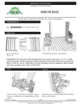
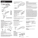
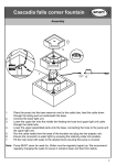
ASSEMBLY INSTRUCTIONS
Cascadia Arbor
11
P L E A S E R E A D C O M P L E T E LY B E F O R E YO U B E G I N A S S E M B LY
CHECK BOX FOR THESE CONTENTS
1
Trellis Caps (7)
2
Headers (2)
3
Braces (4)
4
Lattice Side Panels (2)
1
2
3
HARDWARE
- 1 5/8” Wood screws (26)
- 2 1/2” Wood screws (4)
- Wood block marked “spacer” (1)
4
- Anchoring kit.
TO O L S YO U W I L L N E E D
•
Phillips screwdriver (electric driver recommended)
•
Two bags of concrete mix (60#) to anchor the arbor
HANDY TO HAVE
•
Tape measure
•
Carpenters Square
•
Stool or short ladder
P R E L I M I NA R I E S
ARBOR PAINTING:
Your arbor has been submerged in high quality acrylic primer. An attractive finish coat of quality paint is recommended.
If you decide to repaint your arbor, we recommend that you do so before assembly, it makes the job easier. Be careful
not to cover up guide marks on top of headers.
WORK AREA
Select an area close to where the arbor will be finally placed. While the assembled unit is not very heavy, it is awkward
to move far and requires two people to do so easily.
The assembly area should be relatively flat and open, at least 8’x6’. A lawn, driveway or wide path will be satisfactory.
It is a good idea to lay out the arbor box on your work surface to protect the arbor from nicks and scratches.
445.35.05
Page 2
A T TA C H I N G T H E H E A D E R S TO T H E S I D E PA N E L S
STEP 1
Pilot holes
Lay one of the 2” x 6” header boards flat on your work surface,
with the 12 small pilot holes facing up and the shorter side toward
you.
Place one of the two lattice side panels on its edge, with the upper
end (2 screw holes, closely spaced) toward the header board and
the inside edge of the side post (single screw hole about 12” from
the top) toward the center of the header board.
Drive one of the 1 5/8” screws through the top hole in the bottom
side post, holding the frame up a bit so that the point of the screw
stick through about 1/2” inch.
Choose the pair of pilot holes in the header for the width of opening you prefer.
Outside Holes - for a 48 ½” width opening
Center Holes - for a 42 ½” width opening
Inside Holes - for a 36 ½” width opening
Place the top edge of the frame over the header board with the
point of the screw lined up with the upper pilot hole of the pair
you have selected. When you are sure that the screw point is properly aligned, drive it firmly into the header.
NOTE: Do not drive in the second screw at this time.
IMPORTANT: It is possible to drive a screw into the
wood without using a pilot hole. So, it is critical that you
line up the screw with the pilot hole before you drive in the
screw.
A T TA C H S E C O N D H E A D E R
STEP 2
Turn the assembly over and attach the second header following the same method as the first. Take special care to:
• Make sure the inside edge of the panel (the edge with the single hole 12” from the top of the post) is facing inward.
• Be careful to use the matching pair of screw holes to give you the opening width you have selected.
Page 3
S Q UA R E U P T H E A R B O R
STEP 3
Now square up the arbor. This can be easily done with a large Carpenter’s Square, a tape measure, or even a length
of string as shown below.
“a”
pilot hole
“x”
carpenter’s
square
1.
2.
3.
4.
Measure the distance “a” at post tops.
Set bottom of posts to same spacing “b”.
Measure diagonal distance “x”.
Check opposite diagonal distance “y”.
When a=b and x=y, the arbor is square.
“y”
“b”
When the arbor is squared up, drive the second screw at the top of each post into the lower pilot hole in the
header.
S Q UA R E U P S E C O N D S I D E PA N E L & H E A D E R
Turn the assembly over so that the attached header board is on the upper side, with the free edge of the side
panels on the ground or working surface.
Repeat the process to attach the other header.
A T TA C H T H E B R A C E S TO T H E H E A D E R S A N D PA N E L S
STEP 4
Carefully tip your assembled arbor to the upright position and check
that the side panels are vertical and parallel.
Attach the four braces to the post, using the same technique as for
the header boards: drive the 2 1/2” screw through the bottom hole
in the brace so that it protrudes about 1/2”, and insert the point
into the pilot hole on the inner edge of the panel frame. Then drive
the screw in firmly.
1
Top screw into
back of header
Double-check your side panel posts to make sure they are square
with the header board and parallel to the post on the other side.
When the position is set, hold the upper end of the brace firmly in
contact with the header and drive the screw in.
2
Tighten all screws in your assembly.
Set post screw first
into pilot hole
A T TA C H T H E C A P P I E C E S
STEP 5
Place one of the cap pieces across the two headers,
placing it between the two marks. Center one
screw hole on top edge of header. Secure to both
headers.
Using spacer provided, attach other cap pieces at
equal intervals, 3 boards on each side of the center
one.
I N S TA L L I N G T H E A R B O R
LWO Corporation
3841 N. Columbia Blvd.
Portland, Oregon 97217
(503) 286-5372
(800) 459-8718
www.arboria.com