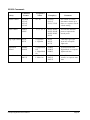
1
“OK, so how does this Digital Drive subwoofer sound? In a word, fabulous.” . . . .“Velodyne’s
New Digital Drive Series is a huge advance in subwoofer technology.”
- John E. Johnson, Jr.
Secrets of Home Theater and High Fidelity, December 2003
“Not only was the little Velodyne the best small sub I’ve ever used, it was one of the very best subs
I’ve used.”
-John Potis
SoundStage!, April 2002
Velodyne Acoustics, Inc.
345 Digital Drive
Morgan Hill, CA 95037
408.465.2800 voice
408.779.9227 fax
408.779.9208 service fax
www.velodyne.com
Service E-mail: [email protected]
Product E-mail: [email protected]
Technical E-mail: [email protected]
Printed on recycled paper
63-DD RevD 12DEC03
TM
Digital Drive
User’s Manual
IMPORTANT SAFETY INSTRUCTIONS
CAUTION
RISK OF ELECTRIC SHOCK
DO NOT OPEN
Caution: To reduce the risk of electric shock, do not remove cover (or back). No user-serviceable parts inside. Refer
servicing to qualified service personnel.
The lighting flash with arrowhead symbol is intended to alert the user to the presence of uninsulated "dangerous voltage"
within the product's enclosure that may be of sufficient magnitude to constitute a risk of electric shock to persons.
The exclamation point symbol is intended to alert the user to the presence of important operating and maintenance
(servicing) instructions in the literature accompanying the subwoofer.
1.
2.
3.
4.
5.
6.
7.
8.
9.
10.
11.
12.
13.
14.
15.
16.
17.
18.
19.
20.
Read Instructions -- All safety and operating instructions should be read before the subwoofer is operated.
Retain Instructions -- The safety and operating instructions should be retained for future reference.
Heed Warnings -- All warnings on the subwoofer and in the operating instructions should be adhered to.
Follow Instructions -- All operating and use instructions should be followed.
Water and Moisture -- The subwoofer should not be used near water -- for example, near a bathtub, washbowl, kitchen
sink, laundry tub, in a wet basement, near a swimming pool, or the like.
Carts and Stands -- The subwoofer should be used only with a cart or stand recommended by the manufacturer to avoid
injury from tipover.
Wall or Ceiling Mounting -- The subwoofer should be mounted to a wall or ceiling only as recommended by the
manufacturer.
Ventilation -- The subwoofer should be situated so that its location or position does not interfere with its properventilation. For example, the subwoofer should not be situated on a bed, sofa, rug, or similar surface that may block the
ventilation openings; or placed in a built-in installation such as a bookcase or cabinet that may impede the flow of air
through the ventilation openings.
Heat -- The subwoofer should be situated away from heat sources such as radiators, heat registers, stoves,
orother subwoofers that produce heat.
Power Sources -- The subwoofer should be connected to a power supply only of the type described in the operating
instructions or as marked on the subwoofer.
Power-Cord Protection -- Power-supply cords should be routed so that they are not likely to be walked on or pinched
by items placed upon or against them, paying particular attention to cords at plugs, convenience receptacles, and the
point at which they exit from the subwoofer.
Caution: To prevent electrical shock, match wide blade of plug to wide slot, fully inserted.
Cleaning -- The subwoofer should be cleaned only as recommended by the manufacturer.
Nonuse Periods -- The power cord of the subwoofer should be unplugged from the outlet when left unused for a
long period of time.
Object and Liquid Entry -- Care should be taken so that objects do not fall and liquids are not spilled onto the enclosure.
Damage Requiring Service -- The subwoofer should be serviced by qualified service personnel when:
a. The power-supply cord or plug has been damaged.
b. Objects have fallen or liquid has been spilled into the subwoofer.
c. The subwoofer has been exposed to rain.
d. The subwoofer does not appear to operate normally or exhibits a marked change in performance.
e. The subwoofer has been dropped or damaged.
Servicing -- The user should not attempt to service the subwoofer beyond what is described in the operating
instructions.
Overloading -- Do not overload wall outlets, extension cords, or integral convenience receptacles as this can result
in a risk of fire or electric shock.
Replacement parts -- When replacement parts are required, be sure the service technician has used replacement parts
specified by the manufacturer or have the same characteristics as the original part. Unauthorized substitutions may
result in fire, electric shock, or other hazards.
Safety Check -- Upon completion of any service or service of repairs to this product, ask the service technician
toperform safety checks to determine that the product is in proper operating condition.
All other servicing should be referred to qualified service personnel.
Velodyne Digital Drive User’s Manual
Page i
Other Velodyne Subwoofer Products:
Signature 1812
TM
TM
SPL Series II
SPL-800
SPL-1000
SPL-1200
Deco System
Deco System
Deco Satellites
CHT Series
CHT-8
CHT-10
CHT-12
CHT-15
CHT Front Row System
DLS Series
DLS-3500
DLS-3750
DLS-4000
VX-10
Velodyne Digital Drive User’s Manual
Page 29
RS-232 Commands
Command
Format
Acceptable n
Values
Volume Control
#VOnn$,
#VO+$,
#VO-$,
#VO?$
00 – 99
#VO25$,
#VO+$,
#VO-$, VO?$
Sets volume to a value,
increments volume up or
down, or requests current
volume setting
Preset Control
#PSn$,
#PS?$
1, 2, 3, 4, 5, 6
#PS1$, #PS2$,
#PS3$, #PS4$,
#PS5$, #PS6$,
#PS?$
Activates the indicated
preset, or requests the
current preset
Logo Light Control #LTn$,
#LT?$
0: Light Off
1: Light On
#LT0$
#LT1$
#LT?$
Turns the Logo Light
on or off, or requests
light state
Night Mode
Control
#NMn$,
#NM?$
#NM0$
#NM1$
#NM?$
Activates/Deactivates
Night Mode, or requests
light mode state
Mute Control
#MUn$,
#MU?$
0: Night Mode
Off
1: Night Mode
On
0: Mute Off
1: Mute On
#MU0$
#MU1$
#MU?$
Mutes/Unmutes the
woofer, or requests mute
state
Activity
Velodyne Digital Drive User’s Manual
Example(s)
Comments
Page 28
WICHTIGE SICHERHEITSHINWEISE
VORSICHT
GEFÄHRLICHE SPANNUNG
NICHT ÖFFNEN
Vorsicht: Zur Vermeidung von Gefahr durch elektrischen Schlag, Deckel (oder Rückwand) nicht abnehmen. Produkt
enthält keine Anwenderteile. Reparatur und Wartung nur von qualifiziertem Fachpersonal vornehmen lassen.
Das Blitzsymbol dient als Hinweis auf unisolierte „gefährliche Spannungen“ innerhalb des Gehäuses, deren Werte
eine Berührungsgefahr für den Menschen darstellen können.
Das Symbol mit dem Ausrufungszeichen dient als Hinweis auf wichtige, in den Unterlagen des Subwoofers
enthaltene Bedienungs- und Wartungsvorschriften.
1. Anleitungen lesen - Alle Sicherheits- und Bedienungsanleitungen vor Inbetriebnahme des Subwoofers
aufmerksam durchlesen.
2. Anleitungen aufbewahren - Die Sicherheits- und Bedienungsanleitungen zur späteren Bezugnahme
aufbewahren.
3. Warnungen beachten - Alle Warnungen am Subwoofer und in der Bedienungsanleitung unbedingt beachten.
4. Anleitungen befolgen - Alle Bedienungs- und Gebrauchsanleitungen genau befolgen.
5. Wasser und Feuchtigkeit - Subwoofer nicht in der Nähe von Wasser aufstellen, d.h. neben einer Badewanne,
Spüle, Waschmaschine, in einem feuchten Keller, in der Nähe des Swimmingpools o.ä..
6. Rollwagen und Ständer - Subwoofer nur mit einem vom Hersteller empfohlenen Rollwagen oder Ständer
benutzen.
7. Wand- oder Deckenbefestigung - Subwoofer nur den Herstellerempfehlungen gemäß an der Wand oder Decke
befestigen.
8. Belüftung - Subwoofer so aufstellen, daß die erforderliche Belüftung nicht behindert wird. D.h., Subwoofer
nicht auf einer weichen Oberfläche wie einem Bett, Sofa, Teppich o.ä. aufstellen, die die Belüftungsöffnungen
blockieren kann. Subwoofer gleichfalls nicht in einem Regal oder Schrank unterbringen, worin die Luftzufuhr
behindert wird.
9. Wärme - Subwoofer nicht in der Nähe von Wärmequellen, wie Heizkörpern, Wärmespeichern, Öfen oder anderen
wärmeerzeugenden Subwoofern aufstellen.
10. Netzanschluß - Subwoofer nur an eine der in der Bedienungsanleitung beschriebenen oder auf dem Subwoofer
angegebenen Stromquellen anschließen.
11. Netzkabelschutz - Netzkabel so verlegen, daß nicht daraufgetreten wird oder sie durch darauf-oder
dagegengestellte Gegenstände eingeklemmt werden können. Die Anschlußstellen des Netzkabels an
Steckdosen und am Subwoofer dabei besonders beachten.
12. „Vorsicht“: Zur Vermeidung von Gefahr durch elektrischen Schlag sicherstellen, daß der Schutzkontakt des
Steckers vollständig in die Steckdose eingeführt ist.
13. Reinigung - Subwoofer nur den Herstellerempfehlungen gemäß reinigen.
14. Betriebsfreie Zeiträume - Netzkabel des Subwoofers aus der Steckdose ziehen, wenn er über einen längeren
Zeitraum nicht benutzt wird.
15. Beschädigungen durch Gegenstände oder Flüssigkeiten - Es ist darauf zu achten, daß keine Gegenstände
auf das Gehäuse fallen oder Flüssigkeiten darauf verschüttet werden.
16. Beschädigungen, die eine Reparatur erforderlich machen - Subwoofer sollte von qualifiziertem Fachpersonal
repariert werden, wenn:
a. Das Netzkabel oder der Stecker beschädigt sind.
b. Gegenstände oder Flüssigkeiten in den Subwoofer gelangt sind.
c. Der Subwoofer dem Regen ausgesetzt wurde.
d. Der Betrieb des Subwoofers gestört ist oder seine Leistung deutlich nachgelassen hat.
e. Der Subwoofer fallengelassen oder beschädigt wurde.
17. Reparatur und Wartung - Durch den Benutzer auszuführende Wartungsmaßnahmen des Subwoofers sind auf
die in der Bedienungsanleitung angegebenen Prozeduren beschränkt.
18. Überlastung - Zur Vermeidung von Brandgefahr und elektrischem Schlag Wandsteckdosen,
Verlängerungskabel bzw. eingebaute Steckdosen nicht überlasten.
19. Ersatzteile - Wenn Ersatzteile benötigt werden, sicherstellen, daß der Servicetechniker entweder die vom
Hersteller angegebenen Ersatzteile benutzt oder Teile, die den Originalteilen entsprechende Kennwerte
besitzen. Die Verwendung von Ersatzteilen, die nicht zugelassen sind, kann Brände, elektrischen Schlag
oder andere Gefahren verursachen.
20. Sicherheitsprüfung - Nach Beendigung von Wartungs- oder Reparaturmaßnahmen an diesem Produkt vom
Servicetechniker Sicherheitsprüfungen zum Nachweis des ordnungsgemäßen Betriebszustandes vornehmen
lassen.
Alle anderweitigen Servicemaßnahmen von qualifiziertem Wartungspersonal durchführen lassen.
Velodyne Digital Drive User’s Manual
Page ii
ATTENTION
Risque d’électrocution
Ne pas ouvrir
Attention: Afin d’éviter tout risque d’électrocution, ne pas enlever le boitier (ou partie arrière de l’enceinte). Aucune
pièce ne doit être manipulée par l’utilisateur. Pour tout entretien, vous référer à un
personnel de service qualifié.
Le symbol de l’éclair avec la flèche sert à avertir l’utilisateur de la présence d’un “voltage dangereux” non isolé
dans l’enceinte du produit d’une magnitude pouvant constituer un risque
d’électrocution de personnes.
Le symbol du point d’exclamation sert à avertir l’utilisateur que d’importants conseils de fonctionnement et de
maintenance (entretien) sont fournis avec l’enceinte d’extrêmes graves.
1. Lire le mode d’emploi - Tous les conseils de sécurité et de fonctionnement doivent être lus avant de mettre en
marche l’enceinte.
2. Garder le mode d’emploi - Il est conseillé de conserver les conseils de sécurité et de fonctionnement pour un
éventuel usage futur.
3. Avertissements - Il est important de se conformer à tous les conseils de fonctionnement concernant l’enceinte
et à toutes les instructions inscrites sur l’enceinte.
4.
Suivre les conseils - Tous les conseils d’utilisation et de fonctionnement doivent être suivis à la règle.
5. Eau et humidité - Ne pas utiliser l’enceinte près d’une source d’eau - par exemple, près de la baignoire, d’une
bassine de lavage, d’un évier de cuisine, d’un bac à lavage, dans un sous-seul mouillé, près d’une piscine…
6. Pieds et Supports - N’utiliser que des pieds et supports recommandés par le fabricant.
7. Assemblage mural ou au plafond - Se conformer uniquement aux instructions du fabricant pour fixer l’enceinte
sur un mur ou sur un plafond.
8. Ventilation - Il est important de placer l’enceinte de telle sorte qu’elle ne gêne pas sa propre ventilation. Par
exemple, ne pas placer l’enceinte sur un lit, un canapé, sur la moquette, ou sur toute surface similaire qui
bloque les ouvertures de ventilation ; ne pas poser l’enceinte dans une meuble encastré ou fermé telle
qu’une bibliothèque ou un meuble qui empêche l’air de circuler par les ouvertures de ventilation de l’enceinte.
9. Chaleur - Placer l’enceinte loin de toute source de chaleur tels que radiateurs, compteurs thermiques, fours
ou autres enceintes dégageant de la chaleur.
10. Sources d’électricité - Ne brancher l’enceinte que dans une prise du type décrit dans le mode d’emploi ou
comme indiqué par le fabricant.
11. Protection du cordon électrique - Les cordons électriques doivent être fixés pour éviter que toute personne
ne marche dessus et que rien ne puisse être placé sur ou contre eux - faire tout particulièrement attention aux
cordons branchés dans des prises électriques, à des réceptacles et à leurs points de sorties de l’enceinte.
12. ”Attention : Afin d’éviter tout choc électrique, introduire la lame la plus large de la fiche dans la borne
correspondante de la prise et pousser jusqu’au fond”.
13. Nettoyage - Pour le nettoyage de l’enceinte, suivre scrupuleusement les instructions du fabricant.
14. Périodes de non-utilisation - Le cordon électrique de l’enceinte doit rester débranché si l’enceinte reste
inutilisée pendant une longue période de temps.
15. Infiltration d’objet ou de liquide - Faire attention à ce qu’aucun objet ne tombe et à ce qu’aucun liquide ne soit
versé sur l’enceinte.
16. Dommages nécessitant réparation - L’enceinte ne doit être réparée que par du personnel qualifié lorsque :
a. le cordon électrique ou la prise ont été endommagés.
b. Des objets sont tombés ou du liquide a été versé sur l’enceinte.
c. L’enceinte a été exposée à la pluie.
d. L’enceinte ne semble pas fonctionner normalement ou indique un changement de performance.
e. L’enceinte est tombée par terre ou a été endommagée.
17. Entretien - L’utilisateur ne doit pas tenter de réparer l’enceinte au-delà de ce qui est décrit dans le mode
d’emploi.
18. Surcharge - Ne pas surcharger les prises murales, les rallonges, ou les prises femelles encastrées de
commodité. On risquerait un incendie ou un choc électrique.
19. Pièces de rechange - Lorsque le remplacement d’une pièce s’avère nécessaire, s’assurer que le technicien
utilise la pièce spécifiée par le fabriquant, ou une pièce possédant les mêmes caractéristiques que la pièce
d’origine. Les substitutions non autorisées peuvent provoquer des incendies ou des chocs électriques, ou
présenter d’autres dangers.
20. Contrôle de sécurité - Après toute intervention technique sur ce produit (neuf ou réparé), demander au
technicien de procéder à un contrôle de sécurité pour vérifier qu’il est en bon état de marche.
Toute autre réparation doit être référée à du personnel qualifié.
Velodyne Digital Drive User’s Manual
Page iii
APPENDIX A: RS-232 Serial Overview and Commands
Introduction
This document outlines Velodyne’s Digital Drive (DD) RS-232 protocol specification. This protocol
indicates how Velodyne 1812 and Digital Drive products receive run-time commands from devices
such as Creston Universal Remote Controls.
Com Port Setup
Use standard communications settings: Baud Rate: 9600, Data Bits: 8, Parity: None, Stop Bits: 1
DD IN and OUT Port Pin Configuration
DD serial ports use a standard configuration that allows direct connection to a PC via a FEMALE to
MALE serial cable. It uses only 3 pins (Transmit, Receive, Ground). The pin configurations are:
IN:
Pin 2 = Transmit
Pin 3 = Receive
Pin 5 = Ground
OUT:
Pin 2 = Receive
Pin 3 = Transmit
Pin 5 = Ground
Runtime Command Format
Byte Number
0
1 to 3 or 4
4 or 5
Byte Description
‘#’
Command and Parameter Data
‘$’
Notes
Header Character
3 to 4 ASCII characters, see formats on next page.
Case sensitive - CAPS ONLY!
Termination Character (required or command is
ignored)
(continued next page)
Velodyne Digital Drive User’s Manual
Page 27
If the protection circuitry is active, the unit may cycle on and off until operating parameters return to
normal. Under more serious conditions, the unit may shut off completely. Normal operation will return
upon cooling, but you may be required to unplug the unit momentarily.
The following conditions require service by a qualified technician:
1.
2.
3.
4.
The power cord has become damaged.
The unit does not appear to operate normally or exhibits a marked change in performance.
The unit has been exposed to water.
Some part of the cabinet or circuitry is physically damaged.
Protection Circuitry
Your new subwoofer is equipped with special protection circuitry to provide maximum performance
with greatest reliability.
The unit is protected against:
1) Overdriving the speaker or amplifier.
2) Overheating the amplifier.
3) Excessive drop in power line voltage.
The first type of protection circuitry that prevents overdriving of the speaker or amplifier operates
constantly without being audible under most situations. In some extreme situations (sustained high
output levels such as pro sound usage), the unit may shut down momentarily. This indicates operation
of the thermal or under voltage protection circuitry. If this should happen, you should reduce the volume
setting or shut the unit off until normal operating conditions return. You may also want to plug the unit
into a different wall outlet, as dropping power line voltage will be most noticeable under strenuous
conditions.
Digital Drive Software Updates
At the heart of Digital Drive functionality is the customized software. From time to time, Velodyne will
publish updates to the Digital Drive software. To determine if your unit is a candidate for a software
upgrade, observe the software version number in the upper left corner of the Main Screen (e.g. V1.2).
Then visit www.velodyne.com/ddupdate and observe the version number of the software available for
download. If this version is higher than the version in your unit, you may want to upgrade the software.
To upgrade the software, you will need an IBM-compatible PC with an available RS-232 9-pin serial
port, and a male-to-female “Mouse Extension” serial cable. This cable is available from any computer
store, your local Velodyne dealer, or directly from Velodyne. Next, proceed to the Velodyne web site and
click on the link to download the software. Upon download, run the software and it will instruct you on
completing the update process.
Thank you for purchasing a Velodyne!
Velodyne Digital Drive User’s Manual
Page 26
Table of Contents
Congratulations ............................................................................................................................... 1
Prior to Installation ..................................................................................................................... 1
Package Contents .................................................................................................................... 2
Product Features and Controls ................................................................................................. 2
Subwoofer ........................................................................................................................... 2
Remote Control ................................................................................................................... 3
Remote Control Buttons ..................................................................................................... 3
Digital Drive Accessory Kit .................................................................................................. 4
Installation Overview ....................................................................................................................... 4
Subwoofer Controls and Ports .................................................................................................. 4
Installation – Step-By-Step .............................................................................................................. 5
Subwoofer Cable Connections .................................................................................................. 5
A Word About Subwoofer Outputs ............................................................................................ 6
A Word About Interconnect Cables ........................................................................................... 7
A Word About Connecting More Than One Subwoofer ............................................................. 7
Onscreen Programming and Setup ................................................................................................ 7
Onscreen Programming and Setup – Overview ....................................................................... 8
Onscreen Programming and Setup – Step-By-Step ................................................................ 11
A Word About Room Placement ............................................................................................... 14
Restoring Defaults .......................................................................................................................... 23
Runtime Mode ................................................................................................................................. 23
About Room Equalization ................................................................................................................ 24
Distortion in Loudspeakers .............................................................................................................. 24
The Velodyne Digital Drive Servo-Control Solution .................................................................... 24
Care Of Your Digital Drive Subwoofer ............................................................................................. 25
Troubleshooting And Service ........................................................................................................... 25
Protection and Circuitry ............................................................................................................. 26
Digital Drive Software Updates .................................................................................................. 26
Appendix A: RS-232 Serial Overview and Commands .................................................................. 27
Table of Figures
Figure 1:
Figure 2:
Figure 3:
Figure 4:
Figure 5:
Velodyne Digital Drive Remote Control ..........................................................................
Digital Drive Rear Panel Connections ...........................................................................
Introductory Screen .......................................................................................................
EQ Setup Screen ..........................................................................................................
System Settings Screen ................................................................................................
Velodyne Digital Drive User’s Manual
3
4
8
9
10
Page iv
Velodyne Digital Drive User’s Manual
by dual spiders for even greater linearity. We designed this motor to produce over one-inch (1-1/4" to
be exact) of linear motion, with a maximum mechanical limit of 1-3/4" peak-to-peak. Also, with this
unique configuration, the distortion products are reduced by a factor of two over conventional single
coil structures with dramatically improved cone control. This driver alone would result in less distortion
than any other non-servo design. After optimizing every remaining part of the loudspeaker, we then
turned to the electronics.
As in our other servo products, we then incorporated closed-loop accelerometer based servo-control
of the loudspeaker. At the heart of this control system is a low mass digital accelerometer rigidly
attached to the voice coil. The accelerometer continuously monitors cone motions, providing a digital
feedback signal for the servo control circuitry. This high-gain system is designed to improve linearity
and reduce distortion approximately 30 times over conventional non-servo systems. While the input
signal is being sent to the amplifier which powers the driver, a continuous signal representing cone
motion is being sent to a computer. This computer constantly adjusts for any deviation between the
input signal and the subwoofer’s output. This self-regulation results in extreme control over cone
movement, and very accurate low distortion sound. All processing of the audio signal is done digitally.
To provide the power for driving this massive loudspeaker, we incorporated an extremely efficient
Class-D switching amplifier. This new amplifier features our patented energy recovery circuit design,
U.S. Patent #4,727,584 and 4,573,189 which drastically reduces wasted energy (heat) as compared
to traditional switching designs. One that is capable of running cool to the touch and providing 1250
watts RMS of power! At typical listening levels, Digital Drive subwoofers produce less than 1% harmonic
distortion with input signals extending to 20Hz. At higher levels the distortion barely exceeds 1%, far
better than any conventional design currently on the market. This combination provides you with the
best combination of clean, deep, accurate bass, without making any sacrifice to distortion.
Care of Your Digital Drive Subwoofer
Do not use any harsh detergents or chemicals to clean the cabinet. Abrasives, detergents, or cleaning
solutions may damage the finish on the cabinet. We recommend using a damp cloth to clean the
cabinet. During normal conditions, your new subwoofer may be left on continuously without any
problems. The unit is equipped with a signal-sensing turn on/off that will automatically turn on the unit
when a signal is present at the inputs and turn off the unit after several minutes when there is no longer
any signal at the inputs. If you plan to leave the subwoofer unused for an extended period of time, we
recommend that you unplug the unit.
Troubleshooting and Service
If you should experience a problem with the operation of your subwoofer, please check all of the following before seeking service. Following is a simple troubleshooting guide to assist you.
1. Verify unit is plugged in and power outlet used is active.
2. Is the unit receiving an input signal from your source? A good way to test this is to connect the
EQ audio out to the LFE input (both on the subwoofer back panel), then enter setup mode (see
Step 6). The woofer should play the sweep tone used for room EQ.
3. Have all controls on subwoofer (volume, crossover, phase, etc.) been properly set?
4. If unit has been running at high levels for an extended period of time, one of the protection
circuits may be engaged.
• Has the built-in amplifier overheated?
• Is your power line voltage sagging under heavy use?
Velodyne Digital Drive User’s Manual
Page 25
About Room Equalization
This section gives some background on room equalization. As a sub plays in a room, the reflections
of the sound waves off the walls create “standing waves,” that is, places in the room where certain
frequencies are louder and others are diminished. In addition to standing waves, every room will also
have locations where cancellations of the sound waves are like black holes that no amount of attenuation
can fill. Thus as a general rule it is better to “cut down” a peak of response rather than to “boost up” a
valley (i.e. possible black hole) of response.
In general, you are looking for a frequency response that is +/- 3dB at all frequencies (it is highly
doubtful that your ear can tell a response that is any better than this). The response will always roll off
at the low end (according to the settings of the subsonic filter), and there should be no dip or peak at
the crossover frequency with the satellites. While the goal is perfectly flat response, this may not be
possible in the higher frequencies of the subwoofer’s response due to peaks or valleys introduced by
the satellites.
Distortion in Loudspeakers
Nonlinear distortion is a problem that plagues all speakers. This particular type of distortion is a
common problem in subwoofers, which must move large amounts of air to produce adequate levels of
deep bass. Nonlinear distortion is defined as any form of distortion that moves energy from one
portion of the audio frequency spectrum to another. When a single tone is applied to a nonlinear
system, the result is harmonic distortion in which some of the energy leaves the system at multiples of
the original frequency. When multiple tones are applied, intermodulation tones are produced, usually
as simple combinations of the input frequencies. Generally, 3% distortion is considered a reasonable
amount for speakers. This means that 3% of the total energy leaving the speaker is at frequencies
other than the intended input signal.
Most subwoofers on the market today however, produce much more than 3% distortion at common
listening levels. Many models we have tested produce greater than 20% distortion at 20Hz when
driven to 100dB. This is a typical output level obtained in many systems, particularly home theater
systems. Even at 1 watt, many conventional units produce several percent distortion. Secondly, the
odd order, higher harmonics are much more offensive to the human ear than the closer 2nd harmonic.
An interesting result of this reduced distortion is that some of the bass, when played over an extremely
accurate subwoofer system, seems to actually be missing. The truth, however, is that the “missing”
bass was never there to begin with! Distortion products of conventional woofers actually add to the
bass spectrum making it appear louder than recorded. This is due to the additional and unwanted
harmonics (distortion) of the fundamental signal. While conventional subwoofers offer little to combat
distortion products, we at Velodyne have developed another way.
The Velodyne Digital Drive Servo-Control Solution
Velodyne Digital Drive subwoofers produce sound in the same manner as conventional loudspeakers:
a cone-shaped piston is forced to move by means of a linear motor. However, this is about the only
conventional part of the subwoofer.
We determined that conventional motors are unacceptable when called upon to produce the amount of
linear motion we desired. This inadequacy led us to design an improved motor structure by incorporating
two coils, operating out of phase in a push-pull configuration within two magnetic gaps and suspended
Velodyne Digital Drive User’s Manual
Page 24
Congratulations!
Congratulations on your purchase of a Velodyne Digital Drive subwoofer system! Digital Drive
technology is the result of years of research and development, combining advanced Digital Signal
Processing (DSP), software, equalizer, audio filter, digital amplifier, digital servo control, and highpressure loudspeaker technologies. The result is new, state-of-the-art in subwoofer design that takes
our traditionally accurate low-frequency sound reproduction to new levels of precision, eliminates
room anomalies, and resolves many tradeoffs that encumber lesser subwoofer designs.
This exceptional subwoofer will provide you with years of unparalleled listening pleasure. Enjoy!
Caution!
Please observe the following instructions to insure safe and proper system operation.
Warning!
To prevent fire or shock hazard, do not expose this equipment to rain or moisture. To avoid electrical
shock, do not open speaker enclosure or amplifier chassis cover. Please observe all warnings on the
equipment itself. There are no user serviceable parts inside. Please refer all service questions to your
authorized Velodyne dealer.
Prior to Installation
Please unpack the system carefully! This unit is heavy. Use caution when lifting or moving to avoid
injury. Remove all staples used to seal the carton as they can scratch the cabinet. Please save the
carton and all packaging materials for future use. Packing this unit in any other carton may result in
severe damage when shipping. Please take a moment to record the serial number and date/location
of purchase in the space provided on the warranty card for future reference or register on-line at
www.velodyne.com.
Caution!
This subwoofer has electronics built into the cabinet. Do not place the cabinet next to sources
of heat such as furnace registers, radiators, etc. Do not place the unit near sources of excessive
moisture, such as evaporative coolers, humidifiers, etc. The power cord should be routed in
such a way that it will not be walked on, pinched, or compressed in any way that could result
in damaging the insulation or wire.
Regardless of where you install your Velodyne subwoofer, it must remain in an upright position (woofer
facing forward). Using, shipping, or otherwise storing the subwoofer in any other position for an
extended period of time may result in damage to the unit not covered by warranty.
Certain types of televisions are particularly sensitive to stray magnetic fields. If your television produces
distorted colors after installing your subwoofer, simply increase the distance between your television
and the subwoofer, until normal color and operation is returned.
Important Note: Turn your subwoofer off before moving it!
Velodyne Digital Drive User’s Manual
Page 1
Package Contents
Your Velodyne Digital Drive Subwoofer consists of the following components:
•
•
•
•
Digital Drive subwoofer
Power cord
Remote control
Digital Drive Accessory Kit, consisting of:
− Calibrated precision microphone
− Microphone windscreen cover
− Tabletop microphone stand
− Microphone stand adapter
− 25-foot video cable
− 25-foot audio cable
− 20-foot XLR microphone cable
Product Features and Controls
Subwoofer
Prominent features of your new Digital Drive Subwoofer include:
• Cones and motor sizes:
− 10" (8" piston diameter) or 12" (9.7" piston diameter) cone with 310 oz. magnet or,
− 15" (12.7" piston diameter) or 18" (15.2" piston diameter) cone with 380 oz. magnet
• Built-in 1250 watt (RMS), 3,000 watt peak power high-efficiency Class-D amplifier
• Tandem 3" voice coils
• Multi-layer resin laminate cone
• High-excursion rubber surround
• Gain compression, anti-clipping circuit to prevent over excursion and amp clipping
• Fixed 80Hz high-pass crossover (RCA output)
• Balanced (XLR) input
• Line-level (RCA) inputs and outputs
• Speaker-level inputs
• Variable volume control
• Frequency response of 20Hz – 120Hz +/-3dB
• Detachable 6-foot AC power cord
• Four rubber ¼-20” threaded support feet (aluminum with rubber inserts on 15” and 18”
models)
• On-screen controls:
− Graphic or Parametric Equalizer controls for room EQ
− Adjustable (15Hz – 199Hz) low-pass crossover
− Multiple staggered low-pass crossovers (6dB/octave, initial to 48dB/octave, ultimate)
− Adjustable (15Hz - 35Hz) subsonic filter
− Multiple staggered subsonic filters (12dB/octave, initial to 48dB/octave, ultimate)
− Variable volume control
− Adjustable phase control (0°, 15°, 30°, 45°, 60°, 75°, 90°, 105°, 120°, 135°, 150°, 165°,
180°)
− Selectable (+/-) polarity
− Theater/Music selection indicator
− Signal sensing auto turn on/off (defeatable)
− 6 presets for customized listening modes and EQ defeat
Velodyne Digital Drive User’s Manual
Page 2
By pressing the SELECT button, you tell the system to save your settings and return to the introduction
screen. Selecting NO returns without saving (i.e. whatever previous settings were in effect will be
used), and CANCEL keeps you in setup mode.
When the unit saves settings, you will see the video flicker and you may hear a slight tick in your main
speakers. This is normal behavior.
NOTE:
The Digital Drive subwoofer stores all of its settings in internal “Flash” memory. This memory
persists even if the woofer is turned off, loses power, or undergoes a programming update,
so you need not worry about losing your customized settings.
Restoring Defaults
There is a feature in Digital Drive that allows you to restore the factory defaults. On the Main Screen,
simply press the 8, 9, and 0 buttons in sequence. If you are successful, the unit will flicker the video
and then restore the main screen. You will have a good idea that the restore defaults was successful
because the system volume will be restored to 30. You can verify the restore of the defaults by
pressing 12345 and viewing the System Response screen. On this screen, all the EQs should be
returned to their original position.
NOTE: After you successfully restore defaults, you must recalibrate the Digital Servo system. This
is done easily -- simply press 6 then 7 on your remote. Your DD unit will emit a 60Hz tone and
display a calibration value on the main screen for 10 seconds, then reset itself.
Runtime Mode
During normal use of your Digital Drive subwoofer, you can use the preset buttons to invoke certain
presets, use the volume control to raise or lower the subwoofer’s volume, use the light and night
buttons to control the logo light and night mode, respectively, and use the mute button to mute the
subwoofer. These settings are shown on the introductory screen, as follows:
Velodyne Digital Drive User’s Manual
Page 23
from the digital servo, and thus the least amount of distortion possible from the subwoofer. The
“theatrical” setting relaxes the servo a bit to allow a bit more distortion to enter the playback, making
an overall louder and more impressive sub for explosions and other theatrical content. The scale
is 1 for theater (least amount of servo gain) and 8 for music (most amount of servo gain).
You will note that presets 1-4 are shipped from the factory with predetermined settings, preset 5’s
contour is set at 0 level from the factory and customizable by the user (i.e. flat), and preset 6 defeats
all the EQs to demonstrate the effect the equalization of the subwoofer has on room response.
24. As a final thought on matching your Digital Drive subwoofer to your room, don’t forget the “objective
listening” test. That is, make sure the unit sounds good to you! Often, you may want to add a bit
more bass than what would normally be considered “flat” even after you remove the major peaks
and valleys to achieve a flat frequency response. This is quite normal because human hearing
“rolls off” rapidly below 100Hz, causing the bass not to sound as loud. This is the basis for the
“loudness contour” switch included on many receivers and preamps. In order for the bass to
sound flat, especially at lower levels, you may need to increase the subwoofer volume in relation
to the satellite speakers. An increase of about 5-8dB is usually adequate. There are two methods
to accomplish this:
1. Raise the internal volume control for the subwoofer in your surround receiver or processor,
or,
2. Raise the volume of your Digital Drive subwoofer after you have finished your room
equalization and other settings. You can observe this difference by watching the system
response graph as you raise the volume.
Of course, all hearing is different, so be sure to perform the above step “to taste.”
25. Your setup is complete! You are now ready to save settings. You can press the EXIT button on the
remote, or position the cursor over the SAVE/EXIT field on the screen and press select. The
system responds with the following screen:
Velodyne Digital Drive User’s Manual
Page 22
−
−
−
Switchable Velodyne logo indicator
Night Mode Maximum volume setting
Save settings indicator
Remote Control
The Velodyne Digital Drive infrared remote control allows you to set up, adjust, and reset your subwoofer
when connected to a television or a video monitor. You will also use your remote to activate preset
listening values, set the subwoofer’s volume up or down, mute the subwoofer, or set a night operational
mode.
Take care not to lose or misplace your remote control as adjustments to the subwoofer (with the
exception of volume control) can only be done using the remote.
NOTE: Two 1.5V AA batteries are required and included for operation of the remote control.
External remote eyes may be ordered from either Velodyne or your local Velodyne audio equipment
dealer.
Remote Control Buttons
A brief description of each button on the remote control follows:
•
•
•
•
•
•
•
•
•
•
•
•
PWR – Causes woofer to stand by if in “Active” standby mode.
Numeric keypad – Used to enter an unlock code to enter
SETUP mode.
SET (+/-) – Increases (+) or decreases (-) a value in a
specified field.
LIGHT – Turns the subwoofer’s front panel Velodyne logo
light on or off.
NIGHT – Limits the output of the subwoofer, and illuminates
the logo’s amber underlining to signify that the subwoofer is
in night mode.
VOL (+/-) – To raise or lower the volume of your subwoofer.
MUTE – Mutes your subwoofer.
EXIT – To exit SETUP mode. The unit will ask if you want to
save settings before exiting.
SELECT — To toggle field values.
RESET – Restores an entered value to its previous value.
MENU – Enters SETUP mode from the introductory screen.
PRESETS – To access the five preset and one EQ defeat
listening modes. Preset by Velodyne, they are user
adjustable.
Figure 1: Velodyne Digital Drive Remote Control
Velodyne Digital Drive User’s Manual
Page 3
Digital Drive Accessory Kit
The Velodyne Digital Drive Accessory Kit contains the following six components:
•
•
•
•
•
•
Calibrated precision microphone
Microphone windscreen cover
Tabletop microphone stand
Microphone stand adapter
25-foot audio/video cable
20-foot XLR microphone cable
Installation Overview
Your new Velodyne servo subwoofer provides for a number of installation options. Read all the
installation information below in order to determine which installation option is best for your system.
Remember to perform all installation procedures with the subwoofer unplugged until instructed
to activate it!
Subwoofer Controls and Ports
The Velodyne Digital Drive subwoofer is set up, configured, and adjusted by the controls, inputs, and
connections located on the rear panel of the unit. Figure 2 shows the location of each of these important
operational interfaces. Brief descriptions of each interface follow.
Figure 2: Digital Drive Rear Panel Connections
Velodyne Digital Drive User’s Manual
Page 4
22. To unselect the EQ, press SELECT again, then use the right and left arrow keys to position the
cursor on another EQ if desired, and repeat step 21, until the room is equalized.
23. Once the room has been equalized, you may want to return to the Settings Setup screen (by
positioning the cursor over the NEXT field on the EQ setup screen and pressing SELECT) and
review/modify the presets. This screen is shown below.
NOTE: This step is required ONLY if you wish to customize the presets.
Features of each preset are:
Volume (+ or – from SYS). This setting deviates the preset’s volume from the established system
volume of the subwoofer. So, if you found during setup that 7 was a good setup volume for the
subwoofer, then preset one would increase the sub’s volume to 10 since it is set as such. This is
shown above. Using the VOL + or VOL – keys on the remote affects the system volume and the
preset volume is adjusted in lock step with the system volume.
Crossover, subsonic filter, phase and polarity settings. Normally these will not change from
preset to preset. However, it may be that you are using different satellites for different listening
modes and wish to set these settings individually for a specific preset. Note that the “setup” values
cascade to the individual values for the presets, but you can change all the individual values if
desired.
Contour frequency and level. These act as an “extra” EQ that can be used to manipulate the
frequency contour of your subwoofer when this particular preset is invoked. For example, notice
that preset one raises the level by 3dB at 35Hz – this is to accommodate action/adventure movie
content.
Theater/Music indicator. This setting allows you to choose between a “theatrical” subwoofer, a
“musical” subwoofer, or somewhere in between. The “musical” setting represents maximum gain
Velodyne Digital Drive User’s Manual
Page 21
NOTE: The following steps use the parametric equalizer to achieve room equalization. If you do not
wish to use the parametric EQ feature, skip to step 23.
20. To use the parametric EQ feature, position the cursor over the EQ and press the SELECT button.
The values for that particular EQ appear on the right hand side of the screen. The following screen
is shown:
21. To manipulate a parametric EQ, you can now use the LEFT and RIGHT arrow keys to move the
frequency up and down, and the SET + and SET – keys to change the Q value. Use the UP and
DOWN arrow keys to adjust the level of the EQ as before. A selected EQ that has been moved,
with its level raised and Q adjusted is shown below:
Velodyne Digital Drive User’s Manual
Page 20
(1)
(2)
(3)
(4)
(5)
(6)
(7)
(8)
(9)
(10)
(11)
(12)
(13)
(14)
POWER – Press the POWER switch to the ON position to activate the subwoofer. If the
unit is to be left unused for an extended period of time, move this switch to the OFF position
to prolong the life of the subwoofer.
117V~60Hz 15A – Connect your detachable AC power plug to this male interface connection.
The detachable cord allows for easy replacement should the original be damaged.
RS-232 IN – Use this port to communicate with your computer (for software updates), a
touch panel remote control, or another upstream Digital Drive subwoofer. See Appendix A
for an explanation of the use of the serial port, available commands, and their formats.
RS-232 OUT – Use this port to communicate with a second “daisy-chained” Digital Drive
subwoofer. Also, the 12V trigger feature requires a 12V trigger signal (polarity irrelevant)
across pins 7 and 9 of this port.
S-Video – This connects to your S-Video compatible TV. NOTE: Only connect to a single
video output at a time.
LFE INPUT – This XLR input jack receives the balanced LFE signal from your receiver or
processor.
MIC INPUT – This XLR input jack is for your XLR microphone cable.
EQ OUTPUT VIDEO/LEFT/RIGHT – Connect the audio/video cable from your accessory
kit to these jacks: yellow plug to VIDEO (connects to an available video input on your
processor or TV), white plug to LEFT, and red plug to RIGHT (these connect to an available
L/R input on your receiver or processor, such as AUX). NOTE: Only connect to a single
video output (i.e. composite or S-Video) at a time.
THRU – These RCA connectors are for sharing the same signal that goes into your
subwoofer with a second “daisy-chained” subwoofer. RCA input comes out of the THRU
jack.
OUTPUT – These RCA connectors incorporate the use of an 80Hz 6 dB/octave slope high
pass crossover.
INPUT LFE – This RCA input jack is for line-level connection.
REMOTE SENSOR - This connection allows for hook-up of the optional remote control
receiver. With this optional receiver plugged in you will be able to utilize the functions of
the remote to control power, volume and mute functions. Place the infrared receiver within
direct line of sight from your usual listening position.
VOLUME UP/DOWN – Press the black UP pushbutton to incrementally raise your
subwoofer’s system volume; press the black DOWN pushbutton to incrementally lower
your subwoofer’s system volume. Note the use of these buttons during software updates.
SPEAKER LEVEL INPUT RIGHT/LEFT – This speaker-level connector allows either banana
plug/jack or exposed wire/terminal connections.
Installation – Step-by-Step
To ensure a quick and flawless installation of your Velodyne Digital Drive unit, follow these numbered
setup instructions in their exact order.
Subwoofer Cable Connections
Make all necessary cable connections between the applicable subwoofer connector port and your
particular home electronics equipment in the following order:
1. Insert the detachable AC power cord into the 117V~, 60Hz, 15A power interface port on the rear
panel of your subwoofer. Plug the male end of the cord into a convenient wall outlet.
Velodyne Digital Drive User’s Manual
Page 5
2. Provide signal to your subwoofer through one or more of the following connections (refer to your
receiver/processor owner’s manual for available inputs to the subwoofer):
a. LFE INPUT (RCA, the RED jack at location 11 on Figure 2) — This is the most common input
cable connection. Make a connection between this input and the LFE output or the subwoofer
output of your receiver or processor; OR
b. LFE INPUT (XLR, location 6 on Figure 2) — Make a connection between this input and the
balanced LFE outputs of your receiver or processor; OR
c. INPUT, LEFT and RIGHT (location 11 on Figure 2) — Make a connection between these
inputs and the stereo outputs of your receiver or processor; OR
d. SPEAKER-LEVEL INPUT (location 14 on Figure 2) — Make a connection between these
inputs and the left and right speaker connections on your receiver or processor. Make this
connection (Figure 2) by either inserting speaker wire into the correct polar terminals, or by
removing the banana plug jack caps and inserting banana plug wire into the jacks.
NOTE
Refrain from routing connections permanently at this time to accommodate subwoofer room
placement as described below.
3. Establish the Line-level connection (optional). Connect to a pre-amplifier’s main outputs and return
them to your amplifier inputs. When installed in this fashion, your satellite speakers will be crossed
over at 80Hz, which removes the lower bass from your amplifier and speakers, enabling them to do
a better job reproducing high frequencies. By utilizing this method, you will have a bi-amplified
system, gaining improved power and headroom for your system.
A Word About Subwoofer Outputs
The Velodyne subwoofer is designed to operate using the full range audio signal for input when using
the digital built-in crossover. Some processors/receivers have a “subwoofer out” jack that is internally
filtered and designed to be used with a conventional amplifier and speaker. In some rare cases,
combining both an external crossover and the one internal to the subwoofer may result in low output
and increased noise. In these installations you may need to bypass the internal crossover in either the
processor or Velodyne subwoofer. In some installations, simply setting one crossover to a higher
frequency (such as 120Hz) will restore maximum performance. To bypass the subwoofer’s internal
crossover when the unit is being fed a low pass signal from another crossover, refer to the SETUP
instructions at step 14.
NOTE: If not using an external crossover, you should use the built-in crossover for optimal performance.
4. Connect the audio/video cable between your subwoofer (EQ OUTPUT VIDEO/LEFT/RIGHT – yellow,
white, and red, respectively) and your electronics (receiver, processor, TV, etc.). Insert the colorcoded cable plugs into the correct EQ OUTPUT receptacle – the yellow plug into the VIDEO jack,
the white plug into the LEFT jack, and the red plug into the RIGHT jack. The opposite ends of this
cable should be connected to your receiver/processor to an available audio input (e.g. AUX). The
yellow VIDEO cable goes to an available composite video input (e.g. aux), and the white/red AUDIO
(L&R) cables go to a corresponding audio input. Consult your receiver/processor and/or TV owner’s
manual for more information.
NOTE: Make sure the audio output goes into your AUDIO system, not your TV! The subwoofer will
generate test tones via the EQ Audio output jacks that are used to match the subwoofer to your
satellites and to correct for room anomalies. In this case, treat the subwoofer EQ audio output
as you would a CD player or other audio device to be played through your receiver or processor.
Velodyne Digital Drive User’s Manual
Page 6
An “equalized” room is shown below:
Velodyne Digital Drive User’s Manual
Page 19
Note that displaying the System Response screen by using the TEST button from the System Settings
screen ONLY allows you to view the system response - you cannot make any changes to EQs or
volume. Press TEST again to return to the System Settings screen.
NOTE: To bypass the low pass crossover, set the frequency to 199Hz.
15. Now adjust the low pass crossover slope. This setting is shipped at 24 dB/octave – a fairly steep
slope to prevent the subwoofer from playing upper frequencies that might call attention to it during
normal operation. At this stage, set the crossover settings under the column entitled SETUP.
Reduce the slope if necessary and use the BACK button to return to the EQ setup screen and
observe the “system response” graph – it should be as flat as possible at the crossover frequency
and immediately to the left and right of it. Too gradual a slope (e.g. 6 dB/octave) may produce a
bump at the crossover frequency, and too steep a slope may produce a dip.
16. You should normally not need to adjust the subsonic filter. Do so only if there are anomalies in the
very lowest frequencies that you cannot address using the normal EQ process as described below.
17. Next, adjust the phase and polarity settings (if needed). Phase is in effect a short delay in the
reproduction of the audio signal. The polarity reverses the phase (i.e. 180o shift). Adjusting phase
can change the dynamics of standing waves and black holes in the room. Sometimes it may be
useful to adjust the phase if there is a particularly difficult peak or valley to eliminate, and/or your
room placement options are limited. Phase and polarity are also important tools to match your
subwoofer to your main speakers. You will often see a dip or peak in the crossover frequency
between your subwoofer and main speakers. Rather than correcting this dip with an EQ, try
adjusting the phase and polarity settings. It is very common for the main speakers to interact with
the subwoofer to diminish or accent frequencies near the crossover point (since this is the point
where both the subwoofer and the speakers are playing the same audio information). Don’t be
afraid to experiment to find the perfect match between your subwoofer and main speakers!
NOTE: The following step shows using the graphic equalizer (using fixed frequencies and Q) to equalize
the room.
18. Next, return to the EQ setup screen and adjust the graphical EQs to eliminate peaks and valleys
from the room response. Use the right and left arrow keys to position the cursor over the EQ you
wish to adjust. If you see a peak in the response at, say, 25Hz (this would be evident in the
“SYSTEM RESPONSE” graph), simply navigate the cursor to the EQ that corresponds to 25Hz
and use the up or down arrow keys to “slide” the EQ up or down. An example of this is shown on
the next page.
19. Continue this process until the system response graph shows a +/-3dB response across the bass
frequencies (that is, up to about 120Hz.). Note that this does not necessarily mean a “ruler flat”
response; +/-3dB is typical for an optimized response curve.
NOTE: Phase and polarity may be useful in eliminating particularly stubborn peaks and valleys. Phase
is in effect a short delay in the creation of the signal, and adjusting phase can change the dynamics of
standing waves and black holes in the room. Sometimes it may be useful to adjust the phase if there
is a particularly difficult peak or valley to eliminate, and/or your room placement options are limited.
Velodyne Digital Drive User’s Manual
Page 18
5. Insert the XLR microphone cable’s 3-pin male plug into the MIC INPUT jack (location 7 on Figure 2)
on the back panel of the subwoofer. For DD-15 and DD-18 units, a microphone jack is also located
on the front of the unit for convenience.
6. Slide the microphone (male connector end first) down through the open, circular sleeve of the
tabletop microphone stand. Position this assembly at a desired listening position from your
subwoofer.
NOTE:
The Digital Drive Accessory Kit includes a microphone stand adapter (1/2”-27 thread) for use
with professional mounting stands. Be sure to first remove the inner thread piece (3/8”-16)
before using.
7. Connect the XLR microphone cable’s female jack end with the male connector end of the
microphone.
8. Sheath the microphone pickup with the foam windscreen cover as a protection against dirt and
airborne contaminants.
A Word About Interconnect Cables
When installing your new Velodyne subwoofer using the line level connections, you should always use
shielded phono cables. There are many quality cables available today, most any of which will work
perfectly well. We do recommend that you keep the length of cable as short as possible to avoid any
potential noise problems.
When routing cables, try to keep them away from equipment that generates significant noise such as
industrial or digital equipment.
A Word About Connecting More Than One Subwoofer
If you are connecting more than one DD subwoofer to your system, you set each woofer up separately,
and then hook them together in a “daisy-chain.” Choose one sub for all the connections described
below (we’ll call this the “primary” sub), and then connect an RCA jack from the THRU RCA jacks of
the “primary” to the Input jacks of the “secondary” sub. You will also need to obtain a “Mouse Extension”
serial cable (available at any computer store, from your Authorized Velodyne dealer, or from Velodyne
directly) and connect the RS-232 OUT port of the primary sub to the RS-232 IN port of the secondary
sub. Then, all runtime commands directed at the primary sub (such as select preset, volume, etc.) will
be communicated to the secondary sub automatically through the serial cable. If you have more than
two subs in your setup, simply continue the daisy chain from the secondary sub to the next sub in the
line (using both RCA and serial connections) and so on.
Note that the daisy chain connection ONLY allows the woofers to communicate basic “run-time”
commands such as volume, and preset. You will want to set up and equalize each sub independently
and optimize it for the room before daisy chaining the subs together.
Onscreen Programming and Setup
BEFORE YOU BEGIN: Once the installation has been completed, you can use your subwoofer without
performing ANY of the setup steps below. Simply use the remote to set the volume, and select the
preset that most closely matches your listening material, and enjoy! However, to reap the maximum
benefits of Digital Drive technology, read on!
Velodyne Digital Drive User’s Manual
Page 7
Onscreen Programming and Setup – Overview
You are now ready to set up and adjust the onscreen audio settings of your Digital Drive subwoofer.
This section provides an overview of the setup process. You will be doing all setup functions with the
buttons of your Velodyne-supplied remote control and seeing the results on your TV screen. Words in
all uppercase letters in the setup instructions (e.g., SELECT, MENU, etc.) identify the specific remote
button to be pressed or selected, or the field on the screen you should be paying attention to. Remember to point the remote control at the subwoofer, not your TV!
Use the RIGHT and LEFT directional arrow buttons that surround SELECT to move through the fields
of the setup screen, and change settings by using the UP and DOWN arrow keys. A screen field
highlighted in reverse video indicates your current location on the screen. Holding down the LEFT or
RIGHT arrow key causes the remote to repeat and you can then rapidly move through fields to arrive at
the desired one. You should be able to perform most of the setup process by using the four arrow keys
and the SELECT button.
Following is an overview of the screens you will be using to set up your Velodyne Digital Drive subwoofer.
Figure 3: Introductory Screen
See Figure 3. This the Introductory screen. Notice that as you change settings (such as preset,
volume, etc.) this is shown on this screen.
You enter setup mode by pressing MENU and entering the code 12345. Upon successful entry of this
code, the system takes you to the EQ Setup screen, as shown in Figure 4.
Velodyne Digital Drive User’s Manual
Page 8
TIP: To see immediate feedback on the effects of your changes to the system response graph, press
the TEST button. The following screen appears:
Velodyne Digital Drive User’s Manual
Page 17
You are now ready to adjust the crossover, subsonic filter, volume, and phase controls of your DD unit.
NOTE: If the remote seems intermittent or unresponsive, be sure you are pointing it at the subwoofer
and not your TV!
AND REMEMBER: Use the RIGHT and LEFT directional arrow buttons that surround SELECT to
move through the fields of the setup screen, and change settings by using the UP and DOWN arrow
keys.
14. Beginning with the low pass crossover, set the frequency to the same value as the crossover
settings on your receiver/processor (for example, many units have a large/small satellite setting).
Again, consult your owner’s manual for more information. You will notice that changing these
values “cascades” the values out to all the presets. That is because once these values are set,
they will not normally change from preset to preset, but if later you wish to customize a specific
preset you can. Remember to use the LEFT and RIGHT arrow buttons for navigation on this
screen, and the UP and DOWN buttons for changing the values. An example of a crossover
changed to 100Hz is shown on the next page.
Velodyne Digital Drive User’s Manual
Page 16
Figure 4: EQ Setup Screen
The EQ Setup screen includes a system response “sweep” window, and a graphic equalizer. You use
these settings to equalize your room. The graphic equalizer features 8 bands, each of which can be
used at its current frequency, or can be infinitely adjusted to the frequency and Q you desire.
REMEMBER: Use the RIGHT and LEFT directional arrow buttons that surround SELECT to move
through the fields of the setup screen, and change settings by using the UP and DOWN arrow keys.
By navigating the cursor to the NEXT field and pressing SELECT, the following screen appears as
shown in Figure 5, next page.
From this screen the crossover, subsonic filter, phase, polarity, theater/music, volume, and other
settings can be set, as well as specifics for each preset, if desired.
Your DD unit comes with 6 presets, four of which are preprogrammed at the factory. The Setup
setting is used to initially set the crossovers, slopes, phase, polarity, and volume for all presets. Then,
each preset can be individually adjusted if desired. The presets are as follows (they are also labeled
on the remote):
1.
2.
3.
4.
5.
6.
Action/Adventure
Movies
Pop/Rock
Jazz/Classical
Custom (off from the factory, or flat)
EQ Defeat
Velodyne Digital Drive User’s Manual
Page 9
Figure 5. System Settings Screen
All six presets contain the following fields:
• Low Pass Crossover Frequency and Slope – Adjust the upper limit of your subwoofer’s
frequency response. Select a crossover setting, in increments of 1, between 15Hz and 199Hz
and slope at 6, 12, 18, 24, 30, 36, 42 and 48 dB/octave.
• Subsonic Filter Frequency and Slope – Set your subwoofer’s subsonic filter (low frequency
limit), in increments of 1, between 15Hz – 35Hz and slope at 6, 12, 18, 24, and 48 dB/octave.
• Phase – Set the phase (delay) of the subwoofer’s output signal, 0 to 180 degrees (adjustable
in 15 degree increments).
• Polarity – Set your subwoofer’s polarity by toggling between positive (+) or negative (-). This
reverses the phase 180 degrees. So, setting the phase at 0 and polarity to + is identical to
setting the phase at 180 and polarity to -.
• Volume – Set your subwoofer’s volume as offset from the setup volume in increments of 1,
between 0 – 99.
• Contour Frequency – This allows you to set a frequency to boost or cut the signal to your
subwoofer in response to specific types of source material. These have been preset at the
factory according to the presets above, but any or all can be customized to taste.
• Contour Level – This indicates the amount of boost or cut at the frequency specified in the
contour frequency. Again, this has been preset at the factory but can be adjusted to taste.
• Theater/Music Indicator – This setting affects the distortion limiting capabilities of the digital
servo system and allows you to choose between a “theatrical” subwoofer, a “musical” subwoofer,
or somewhere in-between. The scale is 1 for maximum theater (least amount of servo gain)
and 8 for maximum music (most amount of servo gain).
Velodyne Digital Drive User’s Manual
Page 10
NOTE: The subwoofer should be turned off when physically moving the unit.
NOTE: If you are constrained in room location positions, don’t worry. By following the setup steps
below, Digital Drive gives you lots of flexibility to make the most out of any room positioning.
11. Now that the room location has been chosen, turn off the subwoofer and the rest of your system
and permanently route the wiring and reconnect to your subwoofer.
12. Reactive the subwoofer and your system and ensure that the system works as before.
13. Use the MENU button to get to the EQ setup screen (after entering the 12345 code), and then
position the cursor over the NEXT field on the EQ setup screen. Press SELECT, and observe the
Sysem Settings screen, as shown on the next page:
Velodyne Digital Drive User’s Manual
Page 15
A Word About Room Placement
Room placement is the first step in equalizing your sub(s) to your room. Subwoofers operate at
extremely low frequencies, which are primarily omni-directional (that is, you can’t usually tell where
they are coming from). As a general rule, placing the sub(s) in the corner(s) of a room will result in the
maximum number of peaks and minimum number of valleys in the response. Remember, the goal is
to find the best location(s) that result in the minimum number and severity of valleys. The worst
location for a subwoofer is typically far away from any walls, and close to the center of your room.
Avoid these locations when possible. When using a pair of Velodyne subwoofers in stereo, it is
preferable to place each subwoofer by the satellite of the same channel. If moving your satellites is an
option, they too can contribute to peaks and valleys and should be likewise placed through
experimentation.
10. Now you can begin moving your subwoofer around the room to find the best placement position.
You need to find the best tradeoff between appearance and room response. Be sure the room is
in the configuration that it will be in when you typically listen – e.g. doors closed, curtains open or
closed, etc. As you move the subwoofer, refer to the “SYSTEM RESPONSE” graph to minimize
peaks and especially valleys in the response curve. As an example, you might find a location that
smoothes the graph as follows (see next page):
Velodyne Digital Drive User’s Manual
Page 14
Other controls on the Setting Setup screen:
•
Auto On/Off Active/Inactive – When active, this control automatically shuts the subwoofer
off after a length of time without any source signal. The woofer automatically wakes upon
receiving input signal again.
•
Night Mode Maximum Volume – When the NIGHT mode button is pressed on the remote,
this setting is invoked. Night mode is indicated by the amber bar underlining the VELODYNE
logo. The subwoofer will not play louder than this volume level until the night mode is defeated.
Onscreen Programming and Setup – Step-by-Step
Follow the steps below in order to activate your subwoofer and determine the best room location for it.
1. Push the POWER switch on the subwoofer’s rear panel to the ON position.
2. Make sure your receiver/processor is on and the volume control is set to minimum.
3. If you haven’t already done so, establish the crossover settings for your satellites. Generally, if
your satellites can be crossed over at 80Hz (that is, accurately reproduce frequencies to this level)
it is an ideal setting. However, some satellites are only flat to 120Hz or even higher. Remember
that the higher the subwoofer is crossed over (to match the satellite crossover settings), the more
likely it is to become directional (that is, you can tell where the bass is coming from). Again, consult
your processor and speakers owner’s manuals for more information.
4. Select the source on your receiver/processor that the DD subwoofer audio output is connected to.
Input should be configured for stereo.
5. Set the video input where you connected the video output as the active TV image. The introductory
screen with the Velodyne logo and “Velodyne Digital Drive” should now appear on your TV screen,
as follows:
6. Press MENU and enter 12345 to enter the EQ setup screen, as follows:
Velodyne Digital Drive User’s Manual
Page 11
Upon pressing 5, you should see the following screen:
Velodyne Digital Drive User’s Manual
Page 12
7. Use the DD remote control to lower the subwoofer’s volume to 00. You can do this by simply
holding down the VOL – button on the remote for a few seconds.
8. Raise the volume on your receiver/processor until the DD test sweep (a tone that sweeps from
20Hz up to 200Hz) can be heard from your system’s speakers. Continue to raise the volume until
the “system response” graph on your TV shows the response of your full range speakers (the right
hand portion of the graph) at approximately 86 dB (or a comfortable listening level). This is shown
below:
9. Now use the DD remote control to raise the level of the subwoofer to match the level of your full
range speakers. That is, the “SYSTEM RESPONSE” graph should be relatively flat (although at
this point there will be peaks and valleys that will be addressed next). The screen should now look
something like this (see next page):
Velodyne Digital Drive User’s Manual
Page 13