1
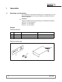
Service Manual
0
LAPARO CO2 PNEU
Automatic Insufflator
2233
SM--2233 / /de--en/ / Index: 09--05--1.0 / ÄM: TD 00--000
Wichtige allgemeine Anwendungshinweise
Das Produkt nur bestimmungsgemäß und unter Beachtung der Gebrauchsanweisung durch entsprechend ausgebildetes und qualifiziertes Fachpersonal einsetzen. Wartung und Reparatur nur
durch autorisierte Fachkräfte.
Das Produkt nur in den Kombinationen und mit dem Zubehör und den Ersatzteilen betreiben, die
in der Gebrauchsanweisung angegeben sind. Andere Kombinationen, Zubehör und Verschleißteile nur dann verwenden, wenn diese ausdrücklich für die vorgesehene Anwendung bestimmt
sind und Leistungsmerkmale sowie Sicherheitsanforderungen nicht beeinträchtigen.
Die Produkte vor jeder Anwendung und Rücksendung zum Schutz von Patient, Anwender und Dritten entsprechend der Gebrauchsanweisung aufbereiten.
Technische Änderungen vorbehalten!
Durch Weiterentwicklungen können Abbildungen und Technische Daten geringfügig abweichen.
Struktur der Sicherheitshinweise
Bildzeichen
Klassifizierung der Gefährdung
WARNUNG!
Das Nichtbeachten kann zum Tod oder zu schwersten Verletzungen führen.
VORSICHT!
Das Nichtbeachten kann zu leichten Verletzungen oder zu Schäden am Produkt führen.
.
.
WICHTIG!
Das Nichtbeachten kann zu Schäden am Produkt oder in der Umgebung führen.
HINWEIS!
Anwendertips für eine optimale Gerätenutzung und sonstige nützliche Informationen.
Important general instructions for use
Ensure that this product is only used as intended and described in the instruction manual by adequately trained and qualified personnel, and that maintenance and repair is only carried out by authorized specialized technicians.
Operate this product only in the combinations and with the accessories and spare parts listed in
the instruction manual. Use other combinations, accessories and spare parts only if they are expressly intended for this use and if the performance and safety requirements are met.
Reprocess the products before every application and before returning them for repair as required
by the instruction manual in order to protect the patient, user or third parties.
Subject to technical changes!
Due to continuous development of our products, illustrations and technical data may deviate slightly from the
data in this manual.
CAUTION -- USA only:
Federal law restricts this unit to be used or sold, except under the supervision of a medical doctor.
Safety instructions and levels of danger
Symbol
Level of danger
WARNING!
Failure to observe can result in death or severe injury.
CAUTION!
Failure to observe can result in slight injury or damage to the product.
.
.
SM--2233
IMPORTANT!
Failure to observe can result in damage to the product or surrounding.
NOTE!
Tips for optimum use and other useful information.
0
DEUTSCH
SM--2233
0
Inhalt
1
1.1
1.2
Generelles . . . . . . . . . . . . . . . . . . . . . . . . . . . . . . . . . . . . . . . . . . . . . . . . . . . . . . . . . . . . . . . .
Bestellung von Ersatzteilen . . . . . . . . . . . . . . . . . . . . . . . . . . . . . . . . . . . . . . . . . . . . . . . . . .
Demontage der Gehäuseabdeckung . . . . . . . . . . . . . . . . . . . . . . . . . . . . . . . . . . . . . . . . . .
1
1
2
2
2.1
2.2
2.3
2.4
2.5
2.5.1
2.6
2.6.1
2.6.2
Wartung . . . . . . . . . . . . . . . . . . . . . . . . . . . . . . . . . . . . . . . . . . . . . . . . . . . . . . . . . . . . . . . . . .
Wichtige Hinweise . . . . . . . . . . . . . . . . . . . . . . . . . . . . . . . . . . . . . . . . . . . . . . . . . . . . . . . . . .
Wartung von Gerät und Zubehör . . . . . . . . . . . . . . . . . . . . . . . . . . . . . . . . . . . . . . . . . . . . .
Sichtprüfung . . . . . . . . . . . . . . . . . . . . . . . . . . . . . . . . . . . . . . . . . . . . . . . . . . . . . . . . . . . . . . .
Elektrische Sicherheitsprüfung nach EN / IEC 60601--1 . . . . . . . . . . . . . . . . . . . . . . . . . .
Mess-- und Hilfsmittel . . . . . . . . . . . . . . . . . . . . . . . . . . . . . . . . . . . . . . . . . . . . . . . . . . . . . . .
Messaufbau Überdrucksimulation . . . . . . . . . . . . . . . . . . . . . . . . . . . . . . . . . . . . . . . . . . . . .
Funktionskontrolle . . . . . . . . . . . . . . . . . . . . . . . . . . . . . . . . . . . . . . . . . . . . . . . . . . . . . . . . . .
Alarm-- / Sicherheitsfunktionen . . . . . . . . . . . . . . . . . . . . . . . . . . . . . . . . . . . . . . . . . . . . . . .
Fehlercodes . . . . . . . . . . . . . . . . . . . . . . . . . . . . . . . . . . . . . . . . . . . . . . . . . . . . . . . . . . . . . . .
3
3
3
4
4
5
5
6
6
8
3
3.1
3.1.1
3.2
3.2.1
3.2.2
3.3
3.4
3.4.1
3.4.2
3.5
3.5.1
3.5.2
3.5.3
Baugruppen . . . . . . . . . . . . . . . . . . . . . . . . . . . . . . . . . . . . . . . . . . . . . . . . . . . . . . . . . . . . . .
Schaltnetzteil (Pos. 0160) . . . . . . . . . . . . . . . . . . . . . . . . . . . . . . . . . . . . . . . . . . . . . . . . . . .
Demontage und Montage der Baugruppe . . . . . . . . . . . . . . . . . . . . . . . . . . . . . . . . . . . . . .
Ventilblock (Pos. 0170) . . . . . . . . . . . . . . . . . . . . . . . . . . . . . . . . . . . . . . . . . . . . . . . . . . . . . .
Demontage und Montage der Baugruppe . . . . . . . . . . . . . . . . . . . . . . . . . . . . . . . . . . . . . .
Funktionsprüfungen . . . . . . . . . . . . . . . . . . . . . . . . . . . . . . . . . . . . . . . . . . . . . . . . . . . . . . . .
Druckminderer--Einheit (Pos. 0180) . . . . . . . . . . . . . . . . . . . . . . . . . . . . . . . . . . . . . . . . . . .
Bedien-- E--Karte (Pos. 0210) . . . . . . . . . . . . . . . . . . . . . . . . . . . . . . . . . . . . . . . . . . . . . . . .
Demontage und Montage der Baugruppe . . . . . . . . . . . . . . . . . . . . . . . . . . . . . . . . . . . . . .
Funktionsprüfungen . . . . . . . . . . . . . . . . . . . . . . . . . . . . . . . . . . . . . . . . . . . . . . . . . . . . . . . .
Steuer--E--Karte (Pos. 0220) . . . . . . . . . . . . . . . . . . . . . . . . . . . . . . . . . . . . . . . . . . . . . . . . .
Messpunkte und Versorgungsspannungen . . . . . . . . . . . . . . . . . . . . . . . . . . . . . . . . . . . . .
Demontage und Montage der Baugruppe . . . . . . . . . . . . . . . . . . . . . . . . . . . . . . . . . . . . . .
Funktionsprüfungen . . . . . . . . . . . . . . . . . . . . . . . . . . . . . . . . . . . . . . . . . . . . . . . . . . . . . . . .
9
9
9
9
9
9
9
9
9
9
10
10
10
10
4
4.1
4.2
4.3
11
11
12
4.6
4.7
4.8
Anhang /Annex . . . . . . . . . . . . . . . . . . . . . . . . . . . . . . . . . . . . . . . . . . . . . . . . . . . . . . . . . . .
Reparaturteile / Repair parts . . . . . . . . . . . . . . . . . . . . . . . . . . . . . . . . . . . . . . . . . . . . . . . . .
Explosionszeichnung / Exploded view . . . . . . . . . . . . . . . . . . . . . . . . . . . . . . . . . . . . . . . . .
Lageplan Schaltnetzteil / Component drawing of Switching Power Supply
(Pos./Item 0160) . . . . . . . . . . . . . . . . . . . . . . . . . . . . . . . . . . . . . . . . . . . . . . . . . . . . . . . . . . .
Lageplan Bedien E--Karte / Component drawing Operation PCB
(Pos./Item 0210) . . . . . . . . . . . . . . . . . . . . . . . . . . . . . . . . . . . . . . . . . . . . . . . . . . . . . . . . . . .
Lageplan Steuer--E--Karte / Component drawing of Control PCB
(Pos./Item 0270) . . . . . . . . . . . . . . . . . . . . . . . . . . . . . . . . . . . . . . . . . . . . . . . . . . . . . . . . . . .
Blockschaltbild / Block diagram (64 157.108) . . . . . . . . . . . . . . . . . . . . . . . . . . . . . . . . . . .
Verdrahtungsplan / Wiring diagram (64 156.251) . . . . . . . . . . . . . . . . . . . . . . . . . . . . . . . .
Pneumatikplan / Pneumatic diagram (64 280.021) . . . . . . . . . . . . . . . . . . . . . . . . . . . . . .
5
5.1
5.2
Protokolle / Reports . . . . . . . . . . . . . . . . . . . . . . . . . . . . . . . . . . . . . . . . . . . . . . . . . . . . . . . 19
Prüfprotokoll / Test Report . . . . . . . . . . . . . . . . . . . . . . . . . . . . . . . . . . . . . . . . . . . . . . . . . . . 19
Wartungsprotokoll / Maintenance report . . . . . . . . . . . . . . . . . . . . . . . . . . . . . . . . . . . . . . . 20
4.4
4.5
SM--2233
13
14
15
16
17
18
I
1
Generelles
1.1
Bestellung von Ersatzteilen
Die zur Bestellung erforderliche Artikelnummer von Ersatzteilen, ist in der
Reparaturteileliste unter der im Service Manual verwendeten Positions-Nummer aufgelistet.
.
WICHTIG!
Folgende Angaben sind bei der Bestellung von Ersatzteilen anzugeben:
D Artikel -- Nr. des Ersatzteiles.
D Modell -- Nr. des Gerätes.
D Serien -- Nr. des Gerätes.
Beispiel
Reparaturteileliste
Pos.
Type / Model
Bezeichnung
Designation
0030
72 311.112
Kaltgeräteeinbaubuchse
Mains socket
0110
64 117.102
Rückwand
Back plate
0160
64 291.022
Gehäusedeckel beschichtet
Top cover epoxy coated
Explosionszeichnung
160
030
110
1
SM--2233
1.2
Demontage der Gehäuseabdeckung
Abb.1
Abb.2
1.5
1.4
1.2
1.3
Abb.3
1.0
1.9
b
a
1.8
1.1
' Benötigtes Werkzeug: Kreuzschlitz--Schraubendreher.
Z 4 Gerätefüße (1.2) abschrauben, Abb.1.
Z Blenden (1.3) von der Halteschiene (1.4) schieben, Abb.2.
Z Die 4 untersten Kreuzschrauben (1.5) entfernen, Abb.2.
Z Gehäuseabdeckung (1.0) in Pfeilrichtung (a) ziehen, bis die Federn
(1.8) frei aus der Frontplatte (1.1) ragen, Abb. 3.
Z Gehäuseabdeckung (1.0) in Pfeilrichtung (b) abheben, Abb. 3.
Z Erdungskabel (1.9) lösen, Abb. 3.
SM--2233
2
2
Wartung
2.1
Wichtige Hinweise
Das Service Manual beschreibt die für das Produkt festgelegten
externen Servicemaßnahmen.
.
2.2
WICHTIG!
Zur Durchführung der Servicemaßnahmen ist die Gebrauchsanweisung
des Produktes unbedingt zu beachten.
Wartung von Gerät und Zubehör
Die Wartung und die Prüfung am Gerät soll zum Schutz des Prüfenden in
der angegebenen Reihenfolge durchgeführt werden:
Z Sichtprüfung
Z Elektrische Sicherheitsprüfung
Z Funktionskontrolle
Die im Abschnitt ”Elektrische Sicherheitsprüfung” angegebenen Prüf-und Messverfahren beziehen sich auf die Prüfung nach EN/IEC 60601--1
Alternativ kann nach DIN VDE 751 geprüft werden.
Für die Beachtung der aktuellen Grenzwerte und die Erfassung / Dokumentation von erstgemessenen Werten ist der Betreiber selbst verantwortlich.
Nach einer Reparatur müssen alle Messwerte (Ausgangswerte) des Geräts anhand der Angaben im Service Manual geprüft und bei Abweichungen neu eingestellt werden.
VORSICHT!
Das Produkt darf nicht betrieben werden, wenn die vorgegebenen
Messwerte nicht erreicht oder die Funktionen nicht erfüllt werden.
.
3
HINWEIS!
Alle Wartungs-- und Prüfarbeiten an Gerät oder Zubehör müssen dokumentiert werden.
SM--2233
2.3
Sichtprüfung
Benennung
Durchzuführende Kontrollen
Gerät und Zubehör
' Sicherheitsgefährdende Verschmutzung und allgemeine Sauberkeit
' Mechanische Beschädigung
' Lose oder fehlende Teile
Bedienelemente
' Mechanische Funktion und Freigängigkeit
Beschriftung / Symbolik
' Vollständig und gut lesbar
Sicherheitsrelevante Aufschriften
(z.B. Warnhinweise)
' Vollständig und gut lesbar
Sicherungseinsätze
' Auf die vom Hersteller auf dem Typenschild angegebenen Werte
(Nennstrom und Abschmelzcharakteristik)
Verkabelung
' Auf einwandfreien Zustand (Sitz, Isolation und Brüchigkeit)
E--Karten
' Korrosion oder andere Beschädigungen
Lampenschild (Nur Lichtquellen)
' Vorhanden und gut lesbar
' Beschädigte Teile sofort austauschen!
2.4
Elektrische Sicherheitsprüfung nach EN / IEC 60601--1
Benennung
Maximal zulässige Messwerte
Grenzwerte nach EN / IEC 60601--1
Schutzleiteranschluss
' ± 0,1 Ohm
' ± 0,1 Ohm
' ± 0,2 Ohm
' ± 0,2 Ohm
Ohne Netzanschlußleitung
Schutzleiteranschluss
Mit Netzanschlussleitung
Prüfbedingung:
Imess 25 A ¦ 10% , V0 ± 6 V , tprüf 5 s bis 10 s , 50 Hz / 60 Hz
Geprüft werden:
Der Widerstand zwischen Schutzleiterkontakt bzw. Schutzleiterstift im Netzstecker und jedem anderen schutzleiterverbundenen
berührbaren metallischen Teil.
Erdableitstrom
' ± 170 µA
' ± 500 µA
Patientenableitstrom
' ± 10 µA
' (N.C.) Normalzustand Typ BF: ± 100 µA
' (N.C.) Normalzustand Typ CF: ± 10 µA
Messpunkte:
Messung am Insufflationsanschluss
Prüfbedingung:
Messanordnung (MD) und Messaufbau nach EN / IEC 60601--1
Geprüft werden:
Der Ableitstrom, der durch den Schutzleiter bzw. vom Anwendungsteil über den Patienten zur Erde fließen kann.
Zusätzliche Hinweise
SM--2233
Den Insufflationsschlauch vom Gerät trennen.
4
2.5
Mess-- und Hilfsmittel
Für die Durchführung der in dieser Service Manual beschriebenen Wartungs--, Reparatur-- und
Testroutinen, sind nachfolgend aufgeführte Hilfs-- und Messmittel unerläßlich. Vergewissern Sie
sich vor einer Reparatur, dass die Messmittel kalibriert und in einem einwandfreien Zustand sind.
Zu Beachten: Angegebene Testkonfigurationen sind ausschließlich für Testzwecke definiert und
keine Anwendungsempfehlung.
Bezeichnung
Zusätzliche Angaben
Multimeter
Echteffektiv
Flowröhre CO2
1--10 l /min,
z.B. von Platon Flow Management
Jays Close, Viables, internet: www. platon.co.uk
Digital--Druckmessgerät
Erforderliche Auflösung: 1 mm Hg
(im Druckbereich unterhalb von 50 mmHg)
z.B.: ”VDM 100” von Fa. ASF, München, oder ”GDH 14 AN” von
Fa. Greisinger electronic, D--93128 Regenstauf
LAPARO CO2 PNEU 2233
2.5.1
CO2-- Flasche
0,75 kg, 2046.961
CO2 --Druckschlauch
74 021.029
Druckminderer CO2
74 007.054
Bauchmodell
muss 30 mm Hg standhalten,
geeignet ist z.B. ein geleerter 3 l -- Infusionsbeutel
Hygienefilter
4171.111
Insufflationsschlauch
8170.101
Connector
64 202.147
Spritze
50 ml
Silikonschlauch
ca. 1 m, 4 x 2 mm
Y--Stück
für Silikonschläuche
Gebrauchsanweisung
GA--A 223
Messaufbau Überdrucksimulation
Hygienefilter
Connector
Spritze
5
Manometer
Silikonschlauch
Y--Stück
SM--2233
2.6
Funktionskontrolle
2.6.1
Alarm-- / Sicherheitsfunktionen
Benennung
Vorbereitung
Durchzuführende Kontrollen
Die Gasflasche mit Druckminderer anschließen und das Absperrventil öffnen.
Der Flaschendruck muss bei der Prüfung im ,,normal Bereich” sein.
Die grüne LED der Flaschendruck--Anzeige leuchtet.
Wechselt während der Prüfung die Flaschendruck--Anzeige von Dauerlicht
(grün) auf blinkend, muss die Prüfung abgebrochen und die Flasche gewechselt werden.
Einschaltzustand (Selbsttest)
Während laufendem Selbsttest:
Die Flaschendruck--Anzeige leuchtet und die Flow--Anzeige wird hochgezählt.
Der Selbsttest dauert maximal 1 min.
Am Ende des Selbsttest erfolgt ein kurzer Ton.
Auf der Digitalanzeige für den Istdruck wird der aktuelle Software--Stand
(2 Stellen) angezeigt.
Nach abgeschlossenem Selbsttest:
Nach bestandenem Selbsttest erscheint auf den Digitalanzeigen für verbrauchte Gasmenge “0.0”, für Flow 0 bis 0,5 l/min und für intraabdominalen
Druck 0 ± 1 mmHg.
Es darf an der Anzeige für verbrauchte Gasmenge keine Fehlermeldung
E01 bis E14 angezeigt werden.
Alle 10 min. wird der zyklische Test durchgeführt, wobei CO2 --Gas durch
das Entlüftungsventil abgeblasen wird.
Flowregelung
Hygienefilter mit Insufflationsschlauch am Patientenausgang anschließen.
Am LAPARO CO2 PNEU einen Solldruck von 25 mmHg vorwählen.
Taste ”INSUFFLATION” betätigen, die Taste muss leuchten.
Auf der Digitalanzeige aktuellen Flow ablesen.
' Aktueller Flow: 1,1 l/min bis 1.5 l/min
Die Flowröhre CO2 1--10 l/min an den Insufflationsschlauch anschließen.
Die Taste “High Flow” betätigen, die Taste muss leuchten.
Einen Sollflow von 5 l/min vorwählen.
' Aktueller Flow laut Digitalanzeige: 4 l/min bis 6 l/min
' Aktueller Flow laut Flowröhre: 4 l/min bis 7 l/min
Einen Soll--Flow von 8 l/min vorwählen. Aktuellen Flow von der Digitalanzeige und von der Flowröhre ablesen.
' Aktueller Flow laut Digitalanzeige: 7 l/min bis 9 l/min
' Aktueller Flow laut Flowröhre: 7 l/min bis 10 l/min
Insufflation ausschalten.
Verbrauchsanzeige
SM--2233
Die Taste ”RESET” betätigen.
Die Digitalanzeige für die verbrauchte Gasmenge zeigt ”0.0” an.
6
Benennung
Druckregelung
Durchzuführende Kontrollen
Einen Solldruck von 15 mmHg und einen Soll--Flow von 10 l/min vorwählen.
Das Druckmessgerät und den Insufflationsschlauch über das Y--Stück am
Bauchmodell anschließen.
Die Taste ”INSUFFLATION” und danach ”HIGH FLOW” betätigen.
Nach kurzer Zeit stellt sich der vorgewählte Druck von 15 mm Hg im Bauchmodell ein. Ein kurzes Überschreiten des Druckes mit anschließender Entlüftung ist zulässig.
' Toleranz der Digitalanzeige: ± 3 mmHg
' Abweichung zur Anzeige des Digital--Druckmessgerätes: ± 3 mmHg
Insufflation ausschalten.
Einen Soll--Druck von 20 mmHg vorwählen.
Die Taste ”INSUFFLATION” betätigen.
Nach kurzer Zeit stellt sich der vorgewählte Druck von 20 mmHg im Bauchmodell ein. Ein kurzes Überschreiten des Druckes mit anschließender Entlüftung ist zulässig.
' Toleranz der Digitalanzeige: ± 3 mmHg
' Abweichung zur Anzeige des Digital--Druckmessgerätes: ± 3 mmHg
Gasvorratsüberwachung
“RESET” betätigen.
Das Absperrventil an der Gasflasche schließen.
Einen Solldruck von 20 mmHg und einen Sollflow von 5 l/min vorwählen.
Insufflation “High Flow” einschalten.
Nach einer kurzen Zeit wechselt die Gasvorratsanzeige von grün Dauerlicht
auf Blinklicht.
Der Alarmton Medium Alarm wird ausgegeben.
Entlüftungsfunktion in der
Betriebsart “HIGH FLOW”
Druckquelle (z.B. Spritze) an Insufflationsschlauch anschließen.
Der LAPARO--CO2 --PNEU muss den anstehenden Überdruck entlüften,
ohne dass der Alarm Überdruck (Medium Alarm) auftritt.
Insufflation aus.
Alarm, Überdruck,
Überdruckschalter
Druckquelle (z.B. Spritze) an Insufflationsschlauch anschließen.
Einen Solldruck von 15 mmHg vorwählen.
Die Entlüftungsöffnung an dem Gehäuseboden verschließen.
Die Taste ,,Insufflation” betätigen.
Wird der Solldruck um 4 mmHg überschritten ertönt der Alarm Überdruck.
-- Alarmton Medium Alarm wird ausgegeben.
Überschreitet der Druck im Insufflationsschlauch 30 mmHg so tritt nach 5 s
Verzögerungszeit der Alarm Überdruck > 30 mmHg auf.
-- Alarmton High Alarm wird ausgegeben.
-- Die Alarm-- LED leuchtet permanent.
-- Auf der Digitalanzeige für die verbrauchte Gasmenge erscheint die
Fehlermeldung E11 und die Digitalanzeige für Druck blinkt.
Der Druck im Insufflationsschlauch steigt auf ca. 50 mmHg an.
Überschreitet der Druck im Insufflationsschlauch 45 mmHg so spricht nach
einer Verzögerungszeit der Überdruckschalter an.
-- Alarmton High Alarm geht in einen Dauerton über
-- Die Alarm-- LED leuchtet permanent.
-- Ventil 2 wird abgeschaltet (Schaltgeräusch)
-- Druckquelle abnehmen.
-- Insufflation ein.
7
SM--2233
Benennung
Durchzuführende Kontrollen
Kurzzeitunterbrechung
Gerät für ca. 10 Sekunden ausschalten.
Nach dem Wiedereinschalten müssen alle zuvor angewählten Funktionen
und Einstellungen noch vorhanden sein.
Werksseitige Grundeinstellung
Einstellung am Gerät:
Soll--Flow:
Soll--Druck:
2.6.2
5 l/min
15 mm Hg
Fehlercodes
Fehlercodes (werden im Display ”Verbrauchte Gasmenge” angezeigt)
Error 01:
CO2 --Flasche geschlossen bzw. leer
Error 02:
Tastendruck beim Einschalten
Error 03:
Spannungsversorgung außerhalb der Toleranz
Error 04:
V1 defekt; Flowmessung defekt; V3 defekt
Error 05:
V2 defekt, Insufflationsschlauch angeschlossen
Error 06:
Druckmessung defekt
Error 07:
Flowmessung defekt
Error 08:
V3 defekt; V2 defekt; Druckmessung defekt; Flowmessung defekt
Error 09:
Sollwert ungültig
Error 10:
Entfällt
Error 11:
Aktueller Druck > 30 mm Hg für mehr als 5 Sekunden
Error 12:
Hardwarefehler allgemein; Druckmessung defekt; V1 defekt; Flowmessung defekt
Error 13:
Druckschalter ”Eingangsdruck” defekt
Error 14:
Elektronischer Druckschalter defekt
Error 15:
Falsche DIL--Schalter--Codierung (elektrische Drucküberwachung schnell / langsam) oder
Druckschalter defekt
SM--2233
8
3
Baugruppen
WARNUNG !
Gefahr durch elektrischen Schlag.
Bei Arbeiten am geöffneten und am Netz angeschlossenen Gerät
besteht Gefahr durch das Berühren spannungsführender Teile.
Arbeiten am geöffeten und unter Spannung stehendem Gerät dürfen
nur unter Beachtung der gültigen Sicherheitsvorschriften und
Schutzmaßnahmen erfolgen.
3.1
Schaltnetzteil (Pos. 0160)
3.1.1
Demontage und Montage der Baugruppe
Z Voreingestellte Karte einbauen und Funktion vollständig überprüfen
(entsprechend Abschnitt 2.6 und GA--A 223).
3.2
Ventilblock (Pos. 0170)
3.2.1
Demontage und Montage der Baugruppe
Z Überwurfmutter öffnen und Ausgangsschlauch abziehen. Zusätzliche
Verschraubung mit dem Gehäuseboden von der Geräteunterseite aus
lösen. Ventile können nicht einzeln getauscht werden.
Funktionsprüfungen
Z Funktion nach Baugruppentausch vollständig überprüfen
(entsprechend Abschnitt 2.6 und GA--A 223).
3.2.2
3.3
Druckminderer--Einheit (Pos. 0180)
Z wird voreingestellt geliefert.
3.4
Bedien-- E--Karte (Pos. 0210)
3.4.1
Demontage und Montage der Baugruppe
Z Frontrahmen komplett ausbauen und E--Karte wechseln.
Funktionsprüfungen
Z Voreingestellte Karte einbauen und Funktion vollständig überprüfen
(entsprechend Abschnitt 2.6 und GA--A 223).
3.4.2
9
SM--2233
3.5
Steuer--E--Karte (Pos. 0220)
3.5.1
Messpunkte und Versorgungsspannungen
Z Stecker X1:
Pin 1 = PFD
Pin 2 = --12V ± 0,4V
Pin 3 = GND
Pin 4 = + 24V
Pin 5 = GND
Pin 6 = + 12V ± 0,4V
Pin 7 = GND
Pin 8 = + 5V
Pin 9 = NC
Pin 10 = + 5V
3.5.2
3.5.3
Stecker X3:
Pin 1 = DS 2 (low)
Pin 2 = DS 1 (high)
Pin 3 = 2V ± 0,4V
Stecker X5:
Pin 1 = GND
Pin 2 = + 5V
Pin 3 = GND
Pin 4 = + 5V
Pin 5 = GND
Pin 6 = Heizung
Pin 7 = GND
Pin 8 = Flow > 2 l / min
Pin 9 = GND
Pin 10 = SDA
Pin 11 = GND
Pin 12 = SCL
Pin 13 = GND
Demontage und Montage der Baugruppe
Z Frontrahmen komplett ausbauen und E--Karte wechseln.
Funktionsprüfungen
Z Voreingestellte Karte einbauen und Funktion vollständig überprüfen
(entsprechend Abschnitt 2.6 und GA--A 223).
SM--2233
10
ENGLISH
SM--2233
0
Contents
1
1.1
1.2
General information . . . . . . . . . . . . . . . . . . . . . . . . . . . . . . . . . . . . . . . . . . . . . . . . . . . . . . .
Ordering spare parts . . . . . . . . . . . . . . . . . . . . . . . . . . . . . . . . . . . . . . . . . . . . . . . . . . . . . . . .
Disassembly of housing cover . . . . . . . . . . . . . . . . . . . . . . . . . . . . . . . . . . . . . . . . . . . . . . . .
1
1
2
2
2.1
2.2
2.3
2.4
2.5
2.5.1
2.6
2.6.1
2.6.2
Maintenance . . . . . . . . . . . . . . . . . . . . . . . . . . . . . . . . . . . . . . . . . . . . . . . . . . . . . . . . . . . . . .
Important notes . . . . . . . . . . . . . . . . . . . . . . . . . . . . . . . . . . . . . . . . . . . . . . . . . . . . . . . . . . . .
Maintenance of device and accessories . . . . . . . . . . . . . . . . . . . . . . . . . . . . . . . . . . . . . . .
Visual check . . . . . . . . . . . . . . . . . . . . . . . . . . . . . . . . . . . . . . . . . . . . . . . . . . . . . . . . . . . . . . .
Electrical safety test to EN / IEC 60601--1 . . . . . . . . . . . . . . . . . . . . . . . . . . . . . . . . . . . . .
Measuring Instrumentation and other Equipment . . . . . . . . . . . . . . . . . . . . . . . . . . . . . . .
Measuring set--up for overpressure simulation . . . . . . . . . . . . . . . . . . . . . . . . . . . . . . . . . .
Function check . . . . . . . . . . . . . . . . . . . . . . . . . . . . . . . . . . . . . . . . . . . . . . . . . . . . . . . . . . . . .
Alarm / safety functions . . . . . . . . . . . . . . . . . . . . . . . . . . . . . . . . . . . . . . . . . . . . . . . . . . . . .
Error codes . . . . . . . . . . . . . . . . . . . . . . . . . . . . . . . . . . . . . . . . . . . . . . . . . . . . . . . . . . . . . . . .
3
3
3
4
4
5
5
6
6
8
3
3.1
3.1.1
3.2
3.2.1
3.2.2
3.3
3.4
3.4.1
3.4.2
3.5
3.5.1
3.5.2
3.5.3
Modules . . . . . . . . . . . . . . . . . . . . . . . . . . . . . . . . . . . . . . . . . . . . . . . . . . . . . . . . . . . . . . . . . .
Switching power supply (item 0160) . . . . . . . . . . . . . . . . . . . . . . . . . . . . . . . . . . . . . . . . . . .
Disassembly and assembly of modules . . . . . . . . . . . . . . . . . . . . . . . . . . . . . . . . . . . . . . . .
Valve block (item 0170) . . . . . . . . . . . . . . . . . . . . . . . . . . . . . . . . . . . . . . . . . . . . . . . . . . . . .
Disassembly and assembly of module . . . . . . . . . . . . . . . . . . . . . . . . . . . . . . . . . . . . . . . . .
Function test . . . . . . . . . . . . . . . . . . . . . . . . . . . . . . . . . . . . . . . . . . . . . . . . . . . . . . . . . . . . . . .
Pressure reducing valve unit (item 0180) . . . . . . . . . . . . . . . . . . . . . . . . . . . . . . . . . . . . . .
Control PCB (item 0210) . . . . . . . . . . . . . . . . . . . . . . . . . . . . . . . . . . . . . . . . . . . . . . . . . . . .
Disassembly and assembly of module . . . . . . . . . . . . . . . . . . . . . . . . . . . . . . . . . . . . . . . . .
Function tests . . . . . . . . . . . . . . . . . . . . . . . . . . . . . . . . . . . . . . . . . . . . . . . . . . . . . . . . . . . . . .
Control PCB (item 0220) . . . . . . . . . . . . . . . . . . . . . . . . . . . . . . . . . . . . . . . . . . . . . . . . . . . .
Measuring points and supply voltages . . . . . . . . . . . . . . . . . . . . . . . . . . . . . . . . . . . . . . . . .
Disassembly and assembly of modules . . . . . . . . . . . . . . . . . . . . . . . . . . . . . . . . . . . . . . . .
Function tests . . . . . . . . . . . . . . . . . . . . . . . . . . . . . . . . . . . . . . . . . . . . . . . . . . . . . . . . . . . . . .
9
9
9
9
9
9
9
9
9
9
10
10
10
10
4
4.1
4.2
4.3
11
11
12
4.6
4.7
4.8
Anhang /Annex . . . . . . . . . . . . . . . . . . . . . . . . . . . . . . . . . . . . . . . . . . . . . . . . . . . . . . . . . . .
Reparaturteile / Repair parts . . . . . . . . . . . . . . . . . . . . . . . . . . . . . . . . . . . . . . . . . . . . . . . . .
Explosionszeichnung / Exploded view . . . . . . . . . . . . . . . . . . . . . . . . . . . . . . . . . . . . . . . . .
Lageplan Schaltnetzteil / Component drawing of Switching Power Supply
(Pos./Item 0160) . . . . . . . . . . . . . . . . . . . . . . . . . . . . . . . . . . . . . . . . . . . . . . . . . . . . . . . . . . .
Lageplan Bedien E--Karte / Component drawing Operation PCB
(Pos./Item 0210) . . . . . . . . . . . . . . . . . . . . . . . . . . . . . . . . . . . . . . . . . . . . . . . . . . . . . . . . . . .
Lageplan Steuer--E--Karte / Component drawing of Control PCB
(Pos./Item 0270) . . . . . . . . . . . . . . . . . . . . . . . . . . . . . . . . . . . . . . . . . . . . . . . . . . . . . . . . . . .
Blockschaltbild / Block diagram (64 157.108) . . . . . . . . . . . . . . . . . . . . . . . . . . . . . . . . . . .
Verdrahtungsplan / Wiring diagram (64 156.251) . . . . . . . . . . . . . . . . . . . . . . . . . . . . . . . .
Pneumatikplan / Pneumatic diagram (64 280.021) . . . . . . . . . . . . . . . . . . . . . . . . . . . . . .
5
5.1
5.2
Protokolle / Reports . . . . . . . . . . . . . . . . . . . . . . . . . . . . . . . . . . . . . . . . . . . . . . . . . . . . . . . 19
Prüfprotokoll / Test Report . . . . . . . . . . . . . . . . . . . . . . . . . . . . . . . . . . . . . . . . . . . . . . . . . . . 19
Wartungsprotokoll / Maintenance report . . . . . . . . . . . . . . . . . . . . . . . . . . . . . . . . . . . . . . . 20
4.4
4.5
SM--2233
13
14
15
16
17
18
I
1
General information
1.1
Ordering spare parts
The part number required for ordering a spare part is listed in the repair
parts list under the item number used in the service manual.
.
IMPORTANT!
Specify the following numbers when ordering spare parts:
D Part number of the spare part.
D Model/type number of the device.
D Serial number of the device.
Example
Repair parts list
Pos.
Type / Model
Bezeichnung
Designation
0030
72 311.112
Kaltgeräteeinbaubuchse
Mains socket
0110
64 117.102
Rückwand
Back plate
0160
64 291.022
Gehäusedeckel beschichtet
Top cover epoxy coated
Exploded view
160
030
110
1
SM--2233
1.2
Disassembly of housing cover
Fig.1
Fig.2
1.5
1.4
1.2
1.3
Fig.3
1.0
1.9
b
a
1.8
1.1
' Required tools: Phillips screwdriver.
Z Unscrew the 4 housing feet (1.2), fig.1.
Z Slide trim plates (1.3) from the rails (1.4), fig.2.
Z Remove the 4 bottom Phillips screws (1.5), fig.2.
Z Pull the housing cover (1.0) as indicated by the arrow (a) until the
tongues (1.8) are disengaged from the corresponding grooves in the
front plate (1.1), fig. 3.
Z Lift off the housing cover (1.0) as indicated by the arrow (b), fig. 3.
Z Disconnect the earthing/ground cable (1.9), fig. 3.
SM--2233
2
2
Maintenance
2.1
Important notes
This service manual describes the external service measures defined for
the product.
.
2.2
IMPORTANT!
For carrying out the service measures the product instruction manual
must be observed.
Maintenance of device and accessories
To protect the technician carrying out the inspection, the maintenance
jobs and inspections must be carried out in the order specified below:
Z Visual check
Z Electrical safety test
Z Function check
The inspection and measuring procedures listed in the section entitled
”Electrical safety test” relate to the test in accordance with EN/IEC
60601--1.
Alternatively the test can be carried out in accordance with DIN VDE 751.
The responsibility for complying with the current limit values and the documentation of any values measured for the first time lies in the hands of
the operator.
After repair all measurement values (specified output values) of the device must be checked as described in the service manual and readjusted
if deviations are observed.
CAUTION!
Do not use this product if the specified measurement values or
functions are not fulfilled.
.
3
NOTE!
Any maintenance or inspection job on the device or its accessories must
be documented.
SM--2233
2.3
Visual check
Item to be checked
Check for
Device and accessories
' Safety--relevant soiling/contamination and general cleanliness
' Mechanical damage
' Loose or missing parts
Controls
' Mechanical function and easy operation
Lettering / symbols
' Completeness and legibility
Safety--relevant labeling
(e.g. warnings)
' Completeness and legibility
Device fuses
' The values specified by the manufacturer on the identification plate
(Nominal current and melting characteristics)
Cables
' For perfect condition (position, insulation and brittleness)
PCBs
' Corrosion or other damage
Lamp plate (light sources only)
' In place and easy to read
' Replace damaged parts immediately!
2.4
Electrical safety test to EN / IEC 60601--1
Maximum admissible
measurement values
Limit values to EN / IEC 60601--1
Protective ground (earth)
connection
' ± 0.1 Ohm
' ± 0.1 Ohm
Protective ground (earth)
connection
' ± 0.2 Ohm
' ± 0.2 Ohm
Item to be checked
Without power cord
With power cord
Test conditions:
Imeas 25 A ¦ 10% , V0 ± 6 V , ttest 5 s to 10 s , 50 Hz / 60 Hz
To be tested:
The resistance between protective ground (earth) contact or
protective grounding (earth) pin in the power plug and other
exposed (bare) metal parts connected to the protective ground
(earth ) conductor.
Ground (earth) leakage
current
' ± 170 µA
' ± 500 µA
Patient leakage current
' ± 10 µA
' (N.C.) Normal condition for BF type: ± 100 µA
' (N.C.) Normal condition for CF type: ± 10 µA
Measuring point:
On the insufflation connection
Test condition:
Measuring device (MD) and measuring setup to
EN / IEC 60601--1
To be tested:
The leakage current which can flow through the protective
ground (earth) conductor or from the applied part via the patient to ground (earth).
Additional information
SM--2233
Disconnect the insufflation tube.
4
2.5
Measuring Instrumentation and other Equipment
In order to carry out the maintenance, repair and test routines described in this Service Manual, the
measuring instrumentation and other equipment listed in the following are compulsory.
Before you start a repair job, make sure that the measuring equipment is properly calibrated and in
perfect working condition.
Please observe the following: The test configurations indicated have been defined for testing
purposes exclusively and do not represent a recommendation for use.
Designation
Additional data
Multimeter
True RMS
Flow tube CO2
1--10 l /min,
e.g. by Platon Flow Management
Jays Close, Viables, Internet: www. platon.co.uk
Digital pressure meter
Required resolution: 1 mm Hg
(in pressure range below 50 mmHg)
e.g.: ”VDM 100” by ASF, Munich, or ”GDH 14 AN” by
Greisinger electronic, D--93128 Regenstauf
5
0.75 kg, 2046.961
CO2 pressure hose
74 021.029
Pressure reducing valve CO2
74 007.054
Abdomen model
must be able to withstand 30 mm Hg,
e.g. an empty 3--liter infusion bag can be used
Hygiene filter
4171.111
Insufflation tube
8170.101
Connector
64 202.147
Syringe
50 ml
Silicon tube
approx. 1 m, 4 x 2 mm
Y--fitting
for silicon tubes
Manual
GA--A 223
Measuring set--up for overpressure simulation
Hygiene filter
Connector
Silicon tube
Pressure
gauge
LAPARO CO2 PNEU 2233
automatic insufflator
2.5.1
CO2 cylinder
Syringe
Y--fitting
SM--2233
2.6
Function check
2.6.1
Alarm / safety functions
Designation
Preparation
Required checks
Connect the gas cylinder with pressure reducing valve and open the stop valve.
During the test, the cylinder pressure should be in the “normal” range.
The green LED of the cylinder pressure indicator is lit.
The test must be stopped and the cylinder changed, if the cylinder pressure
indicator changes from continuous light (green) to blinking light during the test.
Switch--on condition (self--test)
While the self--test is in process:
The cylinder pressure indicator is lit and the flow indicator counts up.
The self--test takes may 1 minute.
The end of the self--test is acknowledged by a brief sound signal.
The digital actual pressure indicator displays the current software version
(2 digits).
Upon completion of the self--test:
After successful completion of the self--test, the digital displays show the following readings: gas volume consumed “0.0”, flow 0 to 0.5 l/min and intraabdominal pressure 0 ± 1 mmHg.
There must be no error message EO1 to E14 on the “gas volume consumed”
indicator.
Every 10 minutes, a cyclic test is carried out, releasing CO2 --gas through the
relief valve.
Flow control
Connect hygiene filter with insufflation tube to the patient output. Pre--select a
nominal pressure of 25 mm Hg on the LAPARO CO2 PNEU automatic insufflator.
Actuate the ”INSUFFLATION” button, the button must light up.
Read the current flow on the digital display..
' Current flow: 1.1 l/min to 1.5 l/min
Connect the flow tube CO2 1--10 l/min to the insufflation tube.
Actuate the “high flow” button, the button must light up.
Pre--select a nominal flow of 5 liters per minute.
' Current flow in accordance with digital display 4 l/min to 6 l/min
' Current flow in accordance with flow tube: 4 l/min to 7 l/min
Pre--select a nominal flow of 8 liters per minute. Read the current flow on the
digital display and on the flow tube.
' Current flow in accordance with digital display: 7 l/min to 9 l/min
' Current flow in accordance with flow tube: 7 l/min to 10 l/min
Switch off insufflation
Consumption indicator
SM--2233
Actuate the ”RESET” button.
The digital display for the gas volume consumed reads ”0.0”.
6
Designation
Pressure control
Required checks
Pre--select a nominal pressure of 15 mm Hg and a nominal flow of 10 liters per
minute. Connect the pressure gauge and the insufflation tube via the Y--fitting to
the abdomen model.
Actuate the ”INSUFFLATION” button and then the ”HIGH FLOW” button.
After a short time, the pre--selected pressure of 15 mm Hg prevails in the
abdomen model. It is permissible that the pressure is briefly exceeded and then
released.
' Tolerance of digital display: ± 3 mmHg
' Deviation from reading of digital pressure gauge: ± 3 mmHg
Switch off insufflation.
Pre--select a nominal pressure of 20 mmHg.
Actuate the ”INSUFFLATION” button.
After a short time, the pre--selected pressure of 20 mmHg prevails in the
abdomen model. It is permissible that the pressure is briefly exceeded and then
released.
' Tolerance of the digital display: ± 3 mmHg
' Deviation from reading of digital pressure gauge: ± 3 mmHg
Gas supply monitoring
Actuate “RESET”.
Close the stop valve on the gas cylinder.
Pre--select a nominal pressure of 20 mmHg and a nominal flow of 5 liters per
minute.
Switch insufflation to “High Flow”.
After a short time, the gas supply indicator switches from green continuous light
to blinking light.
Medium alarm is sounded.
Relief function in the
“HIGH FLOW” mode
Connect a pressure source (e.g. syringe) to the insufflation tube.
The LAPARO--CO2 --PNEU automatic insufflator must release the excessive
pressure without triggering the overpressure alarm (medium alarm).
Switch off insufflation.
Alarm, overpressure,
Overpressure switch
Connect pressure source (e.g. syringe) to insufflation tube.
Pre--select a nominal pressure of 15 mmHg.
Connect the release opening in the housing bottom panel.
Actuate the “Insufflation” button.
If the nominal pressure is exceeded by 4 mmHg, the overpressure alarm is
sounded.
-- Medium alarm is sounded.
If the pressure in the insufflation tube exceeds 30 mmHg, the overpressure
alarm > 30 mmHg is sounded with a delay of 5 seconds.
-- High alarm is sounded.
-- The alarm LED is permanently lit.
-- The digital display for the gas volume consumed shows error message
E11 and the digital display for pressure blinks.
The pressure in the insufflation tube increases to approx. 50 mmHg.
If the pressure in the insufflation tube exceeds 45 mmHg, the overpressure
switch is triggered with some delay.
-- The high alarm changes to a continuous alarm.
-- The alarm LED is permanently lit.
-- Valve 2 switches off (switching sound)
-- Remove the pressure source.
-- Switch insufflation on.
7
SM--2233
Designation
Required checks
Brief interruption
Switch off the device for approx. 10 seconds.
When switching on again, all the pre--selected functions and settings must still
be active.
Basic factory setting
Settings on the device:
Nominal flow: 5 l/min
Nominal pressure: 15 mm Hg
2.6.2
Error codes
Error codes (are displayed on the “gas volume consumed” display).
Error 01:
CO2 cylinder closed or empty
Error 02:
Button is pressed when switching on
Error 03:
Power supply out of tolerance
Error 04:
V1 defective; Flow measurement defective; V3 defective
Error 05:
V2 defective, insufflation tube closed
Error 06:
Pressure measurement defective
Error 07:
Flow measurement defective
Error 08:
V3 defective; V2 defective; pressure measurement defective; flow measurement defective
Error 09:
Invalid nominal value
Error 10:
Not applicable
Error 11:
Current pressure > 30 mm Hg for more than 5 seconds
Error 12:
General hardware error; pressure measurement defective; V1 defective; flow measurement defective
Error 13:
“Input pressure” pressure switch defective
Error 14:
Electronic pressure switch defective
Error 15:
Wrong DIL switch coding (electric pressure monitoring fast / slow) or Pressure switch defective
SM--2233
8
3
Modules
WARNING !
Danger of electric shock.
Danger of touching live parts when working on open devices which
are connected to the power supply / mains.
Any work on the open device while the device is connected to
power, may only be carried out provided the valid safety regulations
and protective measures are observed.
3.1
Switching power supply (item 0160)
3.1.1
Disassembly and assembly of modules
Z Install pre--set card (PCB) and check complete function (in accordance
with Section 2.6 and GA--A 223).
3.2
Valve block (item 0170)
3.2.1
Disassembly and assembly of module
Z Open the union nut / locking collar and pull off the outlet tube. Unscrew
the additional screw connection to the housing bottom plate from underneath the device. The valves cannot be replaced individually.
Function test
Z Check the full range of functions after replacing the modules
(in accordance with Section 2.6 and GA--A 223).
3.2.2
3.3
Pressure reducing valve unit (item 0180)
Z The unit is supplied in pre--set condition.
3.4
Control PCB (item 0210)
3.4.1
Disassembly and assembly of module
Z Remove the front frame assembly and replace the PCB.
Function tests
Z Install pre--set card (PCB) and check full range of functions
(in accordance with Section 2.6 and GA--A 223).
3.4.2
9
SM--2233
3.5
Control PCB (item 0220)
3.5.1
Measuring points and supply voltages
Z Plug X1:
3.5.2
3.5.3
Pin 1 = PFD
Pin 2 = --12V ± 0.4V
Pin 3 = GND
Pin 4 = + 24V
Pin 5 = GND
Pin 6 = + 12V ± 0.4V
Pin 7 = GND
Pin 8 = + 5V
Pin 9 = NC
Pin 10 = + 5V
Stecker X3:
Pin 1 = DS 2 (low)
Pin 2 = DS 1 (high)
Pin 3 = 2V ± 0.4V
Stecker X5:
Pin 1 = GND
Pin 2 = + 5V
Pin 3 = GND
Pin 4 = + 5V
Pin 5 = GND
Pin 6 = Heating
Pin 7 = GND
Pin 8 = Flow > 2 l / min
Pin 9 = GND
Pin 10 = SDA
Pin 11 = GND
Pin 12 = SCL
Pin 13 = GND
Disassembly and assembly of modules
Z Remove the front frame assembly and replace the PCB.
Function tests
Z Install the pre--set card (PCB) and check the full range of functions
(in accordance with Section 2.6 and GA--A 223).
SM--2233
10
4
Anhang /Annex
4.1
Reparaturteile / Repair parts
Pos./
Item
Type / Model
0010
Bezeichnung
Designation
72 311.144
Kombi--Filter mit 2 Sicherungen
Combi filter with 2 fuses
0030
64 073.072
Schlauchanschluss für CO2 --Pneu
Hose coupling for CO2 --Pneu
0040
72 316.229
Membrandruckschalter 1--10 bar
Diaphragm pressure switch
0050
74 002.141
Dichtung G 1/4” PA 6
Seal G 1/4” PA 6
0060
74 007.057
Mini Sicherheitsventil G1/4 ”
Mini safety valve G1/4”
0080
64 074.074
Filteranschluss
Filter connector
0090
64 113.113
Druckstück
Pressure fitting
0100
64 064.280
Arretierhülse
Retaining sleeve
0110
64 010.023
Gehäusedeckel, kpl.
Top cover, cpl.
0120
64 070.604
Gerätefuß, kpl.
Equipment foot, cpl.
0130
64 204.165
Halteschiene
Support bar
0140
64 127.065
Blende
Shield
0150
64 010.024
Deckel, kpl. rot
Cover, cpl. red
0160
72 321.394
Schaltnetzteil
Power Supply
0170
72 321.395
Ventilblock
Valve unit
0170
72 321.395A
Ventilblock *
Valve unit *
0180
64 110.364
Druckminderer, nachgearbeitet
Pressure regulator, reworked
0190
64 211.126
Frontrahmen, kpl.
Front frame, cpl.
0200
64 159.882
Frontplattenfolie
Front plate foil
0210
64 352.130
Bedien E--Karte
Operation PCB
0220
64 352.132
Steuer E--Karte
Control PCB
71 620.000
Silikonschlauch, 1,0m (4 x 2 mm)
Silicon tube, 1.0m (4 x 2 mm)
0250
71 620.034
Silikonschlauch, 1,0 m ( 2 x 1,5 mm)
Silicon tube, 1.0 m ( 2 x 1.5 mm)
0260
71 620.035
Silikonschlauch, 1,0 m (8 x 3 mm)
Silicon tube, 1.0 m (8 x 3 mm)
0270
64 226.307
Schlauch, druckfest 140 mm
Tube, pressure--proof 140 mm
0230
0240
* = (A) :
Reparaturaustausch, nur gegen Einsendung der defekten Baugruppe /
Repair exchange, only available by sending in the defective module
' Positionsnummern siehe Explosionszeichnung
' For position numbers see exploded view
11
SM--2233
4.2
Explosionszeichnung / Exploded view
0110
0150
0130
0140
0120
0030
0040
0010
0060
0050
0270
0180
0170
0250
0160
Sicherung / Fuse
F5
A
6,3x32mm
A
0230
0240
0260
0100
0080
SM--2233
0090
0220
0210
0200
0190
12
4.3
Lageplan Schaltnetzteil / Component drawing of Switching Power Supply
(Pos./Item 0160)
Voltage Adjust
PIN 1
J2
T1
PIN 1
C8
13
L1
J1
F1
SM--2233
Lageplan Bedien E--Karte / Component drawing Operation PCB
(Pos./Item 0210)
S10
4.4
OFF
SM--2233
S8
SU1
R45
LD25
LD17
S6
S7
LD16
S5
S4
LD15
LD14
LD13
ON
14
4.5
Lageplan Steuer--E--Karte / Component drawing of Control PCB
(Pos./Item 0270)
4
1
4
X5
1
IC10
IC16
10
60
X1
S1
X3
IC37
44
43
61
27
26
IC39
15
SM--2233
SM--2233
0210
0220
Control PCB cpl.
pressure
sensors
0160
switching
power pack
0010
Mains (line)
filter
Mains (line) voltage
4.6
Blockschaltbild / Block diagram (64 157.108)
16
17
0010
0170
valve block
0210
0220
0160
Verdrahtungsplan / Wiring diagram (64 156.251)
switching
power supply
4.7
SM--2233
Pneumatikplan / Pneumatic diagram (64 280.021)
Pressure relief
4.8
SM--2233
18
5
Protokolle / Reports
5.1
Prüfprotokoll / Test Report
Betreiber / User: ..................................................................... Typen Nr. / Type No.: ..............................
Anschrift / Address: ...................................................................................................................................
Durchgeführte Prüfung
Test carried out
19
Serien Nr.
Serial No.
Datum
Date
Name / Unterschrift
Name / Signature
SM--2233
5.2
Wartungsprotokoll / Maintenance report
Betreiber / User: .................................................................... Typen Nr. / Type No.: ..............................
Anschrift / Address: .................................................................................................................................
Wartungsmaßnahmen
Servicing check up
SM--2233
Serien Nr.
Serial No.
Datum
Date
Name / Unterschrift
Name / Signature
20
GERMANY
RICHARD WOLF GmbH
D--75438 Knittlingen
Pforzheimerstr. 32
Tel.: (..49)--(0)7043--35--0
Fax: (..49)--(0)7043--35300
MANUFACTURER
E--mail:
Internet:
[email protected]
www.richard--wolf.com
USA
RICHARD WOLF
Medical Instruments Corp.
353 Corporate Woods Parkway
Vernon Hills, Illinois 60061
Tel.: 847--913 1113
Fax: 847--913 1488
E--mail: sales&[email protected]
Internet: www.richardwolfusa.com
UK
RICHARD WOLF UK Ltd.
Waterside Way
Wimbledon
SW 17 0HB
Tel.: 020--8944 7447
Fax: 020--8944 1311
E--mail: [email protected]
Internet: www.richardwolf.uk.com
BELGIUM
N.V. Endoscopie
RICHARD WOLF Belgium S.A.
Industriezone Drongen
Landegemstraat 6
B--9031 Gent --Drongen
Tel.: +32 9.280.81.00
Fax: +32 9.282.92.16
E--mail: [email protected]
FRANCE
RICHARD WOLF France S.A.R.L.
Rue Daniel Berger
Z.A.C. La Neuvillette
F--51100 Reims
Tel.: +33 3.26.87.02.89
Fax: +33 3.26.87.60.33
E--mail: [email protected]
AUSTRIA
RICHARD WOLF Austria
Ges.m.b.H.
Wilhelminenstraße 93 a
A--1160 Wien
Tel.: +43 1-- 405 51 51
Fax: +43 1-- 405 51 51--45
E--mail: [email protected]
Internet: www.richard--wolf.at
21
SM--2233