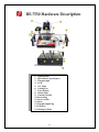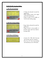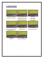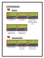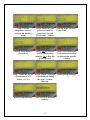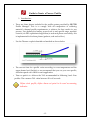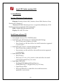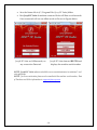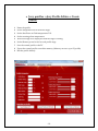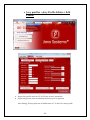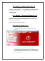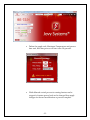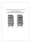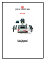
1
JOVY SYSTEMS RE-7550 User Manual Rev. 1.00 Index - Introduction ……………………………………………........... 3 - Copyrights and Liability disclaimer…..………….....……... 3 - Specifications………………………….………………….…… 4 - Safety/ Caution instructions...………......………………. 4 - RE-7550 hardware description …….........……….……..…… 6 - PC Suite Version 2.00 installation…………………………….6 - Operation through Machine interface ….………….................7 - Guide to create Process profile ……………………………….13 - Jovy PC Suite Version 2.00 ……………………………………15 - Jovy PC Suite Operating Guide……….………………………18 -2- Introduction The IR Technology used gives the RE-7550 the opportunity to fit in a wide range and variety of applications fields, for example, GSM, Networking, Medical, and Military fields as well. This makes RE-7550, the optimum solution to a large sector of the BGA & SMD reworking communities. This manual structure enables a technician with no previous knowledge of the system, to become familiar with the operation and maintenance using RE7550 Reworking System. The safety section of the manual explains the inherent dangers presented by any type of soldering/de-soldering equipment and warnings to minimize the risk of injury due to ignorance. Copyrights and Liability Disclaimer The RE-7550 package, including any hard copies and soft copies, are copyright protected. The purchase of the programs confers the right to make back-up copies of the software included in the package only. To the maximum extent permitted by applicable law, in no event shall manufacturer be liable for any damages whatsoever (including without limitation, special, incidental, consequential, or indirect damages for personal injury, loss of business profits, business interruption, loss of business information, or any other pecuniary loss) arising out of the use of or inability to use this product, even if manufacturer has been advised of the possibility of such damages. In any case, manufacturer’s entire liability under any provision of this agreement shall be limited to the amount actually paid by you for the SOFTWARE and/or HARDWARE. -3- Specifications Top heater Power Max. 300W Pre heater Power Max. 800W Voltage frequency 220 Volts 50/60Hz Max board Size 200 mm x 200 mm Gross weight 14 KG Operation Temperature +5~+45 C / +41~+113 F Operation Humidity 20~95% Safety/Caution instructions For Safety reasons, please note the following carefully This unit operates by electricity, and some components within the device have high dangerous voltages applied to them. Failing to follow the operating instructions could result in death, serious injuries, and/or extensive damage to property! Never open the housing or one of the Infrared heaters while main plug is connected. Do not use the units for any purpose other than which they are intended to use it according to the operating instructions. This equipment must not be switched on or used without supervision. The unit should switched-off or in idle state while not in use, leaving it ON may cause overheating. Do not place any flammable material on the vicinity of the Infrared heater. -4- Do not allow the spillage of any liquid to on the ceramic emitter as damage may occur. Please use the Infrared heater only on a level and non-flammable surface. When the Infrared heater is in use, its housing and the areas exposed to the infrared rays can reach high level of temperature. Please do not touch the housing until it cooled down. Any maintenance of the units is only permitted by a JOVY SYSTEMS certified service technician. Please also pay attention to the safety regulations applied in your area. -5- RE-7550 Hardware Description 1- Upper Heater 2- Down Heater (Pre-Heater) 3- Thermocouple 4- LCD 5- X-Y Table 6- Cooling Fan 7- Laser Pointer 8- Guard Glass 9- Control Switches 10- Power Plug 11- Power Switch 12- Fuses 13- Thermocouple Plug 14- USB Port 15- Picking-Up Tube -6- Operation A) Keys Functions of RE-7550 - Upper Heater (UP-Down keys): Used to scroll up/down through menu items and to set the Upper Heater operating power level (percentage from 0% to 100%). - Lower Heater (UP-Down keys): Used to change the value (Up) to increase and (Down) to decrease, as well to set the Lower Heater operating power level (percentage from 0% to 100%). - OK/Menu: used to open menu and also to select any item inside the Menu . - Fan/Cancel: it has two statuses, 1st when you are viewing a menu it will act to cancel and 2nd when you are outside any menu it will power ON/Off the cooling Fan. - Pump: used to Power Pump ON/OFF only. -7- B) RE-7550-E01 Operating Modes: 1 - RE-7550 in Park Mode: - Cooling fan directed toward the application. - Laser pointer points the target inside the Heating area. - Target located in the middle of lower heater heating range 2– RE-7550 in Normal Mode: - Upper heater directed toward the application. - Target located in the middle of both the upper and lower heaters heating range. 3- RE-7550 in USB Mode : - Connect the USB cable between the machine and the computer. - Run Jovy PC Suite, the machine automatically run on USB mode. -8- C) Machine Settings From the main Menu scroll down to Settings. Safety set point, at this temperature value all heaters switch off and external fan switch on. Temperature measurement unit, °Celsius or °Fahrenheit. Activate or de-activate the security password to lock the machine access. Change the default password (9999). Adjust the manual process alarm set point. Set Keypad tone to ON/Off Set LCD backlight Timer from 1 to 10 minutes. -9- D) Manual Process (User define heaters power level) - Adjust the PCB to the XY table out of operation area. - Every time you power ON the machine you should leave the Lower Heater at 100% 2 min until the Guard Glass become saturated with heat. - You should align the PCB using the Laser pointer so that the pointer will be in the center of the desired component. - Make sure that the machine is situated in Park Mode. - Put the Thermocouple (TC) in any place near to the desired component. - Adjust the lower Heater to the desired power level. - If you have any component which can be affected or damaged by excess heat, you should cover it with reflective tape to prevent Infrared rays to reach it. - Pre heat until the PCB reaches a temperature from 80°C to 120°C. - Adjust the upper heater to the desired power level then rotate the upper heater so the machine enters the Normal Mode. - Monitor the screen until the PCB reaches a temperature between 180°C and 230°C. - Switch the Pump On to pick up the component (BGA, CSP, etc…) by the suction pen or use any other removal tool like tweezers to remove other type of components (plastic parts, connectors, etc…). - Turn the machine to Park Mode and switch the Fan On (Fan Button) to start the cooling stage. From Main menu select Manual Control Adjust the U.H (upper heater) and L.H (lower heater) power levels Press Ok to start the process and cancel to stop the process any time. Heaters power level could be changed during the running process. -10- F) Profile Manager Menu Main Menu Select Profile Manager and press OK. Option One: create a new profile Option Three: Delete a saved profile from machine memory Option Four: Delete all saved profiles from machine memory Option Two: Choose a saved profile (it is available to save up to 50 profiles into Machine memory Create a Process Profile From Profiles Menu Select Create profile Step 1: Set time for dwell on peak temperature -11- Step 2: define end temperature value for each profile stage Step 3: Set the temperature value to activate the warning alarm Step 4: Define the UH power level and LH power level for each Profile stage - Preheat Reflow Stage Heaters Power level Step 5: Yes to save the profile into Machine memory, No to Run the profile process Step 6: save the profile to its location according to the machine profiles counter Step 7: Name the profile choose from A to Z letters , or 1 to 9 Step 8: Create a Message to be displayed during the stage – Preheat Message. Soaking Stage Message. Reflow Stage Message. Then Saving to machine memory. -12- Soaking Stage Heaters Power level Guide to Create a Process Profile: 1- Introduction: - There are three phases included in the profile system provided by RE-7550 Profile Manager. This is to comply with all composition of soldering material’s thermal profile requirements to achieve the best results in any process. User defines the heaters power level in each profile stage, machine controls (via PID sophisticated algorithm) to end each phase successfully, this is implemented in the three phases (preheat, soak and re-flow). Use the Thermo couple in bended end method as shown below - The success time for a profile varies according to room temperature and the upper heater level (height) so we recommend that you use your own profile, and after spend a few trails for each application. - Time on peak is to Achieve the TAL recommended in Soldering Lead –Free profiles. The common TAL value between 20 to 60 seconds. Before start profile, define alarm set point to be used as warning indicator. -13- 2- Recommended profile parameters : “Soldering a Lead – Free application” Time on Peak: 30 seconds Preheat: UH level set to 3, UH power value is 80%, LH power value is 100% and preheats end temperature value is 120°C Soaking: UH level set to 3, UH power value is 90%, LH power value is 75% and preheats end temperature value is 200°C Reflow: UH level set to 3, UH power value is 70%, LH power value is 50% and preheats end temperature value is 217°C -14- Jovy® PC Suite version 2.00 1- Installation Systems Minimum Requirements: Platforms: Windows Server 2003, Windows Server 2008, Windows Vista, Windows XP, Windows 7. Processor: 400 MHz Pentium processor or equivalent (Minimum); 1GHz Pentium processor or equivalent (Recommended). RAM: 128MB RAM (Recommended 256). Display: 800 x 600, 256 colors. Install from software CD Insert Jovy® software CD to CD/DVD reader. Install Microsoft .NET Framework 3.5 Redistributable Package. o Run CD drive then windows OS folder. o Run dotnetfx.exe file then follow the install instructions appeared on your screen. Install Microsoft Visual C++ Runtime Redistributable. o Run CD drive then windows OS folder. o Run runtimec.exe file and follow the install instructions appeared on your screen. Install Jovy® PC Suite. o Run CD drive. o Run Jovy®_PC Suite_v2.00_Installer.exe file and follow the install instructions appeared on your screen. Install Jovy USB Driver. o Run Jovy® PC Suite installation Directory. Default directory (C:\Program Files\Jovy PC Suite) o Open Drivers folder. o Run JovyUSBInstaller.exe and follow the install instructions appeared on your screen. -15- Save the license file in (C:\Program Files\Jovy PC Suite) folder. Run Jovy® PC Suite if machine connected Suite will Run on online mode if not connected will run on offline mode as Shown in Figures below Jovy® PC Suite on Offline mode, no Jovy® PC Suite detected RE-7550 and any connection Detected. displays the machine serial number. NOTE: Jovy® PC Suite software should be run as an administrator in windows 7 and vista platforms. NOTE: for license activation please send an email with the machine serial number, Date of Purchase and Seller information to [email protected]. -16- 2- Jovy® PC Suite Main Interface Thermocouple status Connected/Dis-connected Machine mode Park /Normal mode Temperature value as measured from Thermocouple Machine status connected/Online, Dis-connected/Offline -17- Time scale on Minutes/Seconds 3- Jovy® PC Suite Operating Guide lines Tools -> Machine settings Temperature measurement Unit °C/°F Interface Language English/ Chinese Product ID (RE-8500 or others) Machine firmware version Safety Set point, immediate Switch off of heaters and operates the cooling Fan -18- Jovy profiles ->Jovy Profile Editor -> Create profile 1 Name the profile 2 Set the temperature for each Profile stages 3 Set the dwell time on Peak temperature TAL 4 Set the warning alarm temperature 5 Write a message to be displayed while the stage is running 6 Set the Heaters power levels for each profile stage 7 Save the created profile to the PC 8 Export the created profile to machine memory (Memory can save up to 50 profile) 9 Run the profile directly -19- Jovy profiles ->Jovy Profile Editor -> Edit Profile 1 Import any profile saved on PC to Edit one or more parameter 2 Import any profile saved on Machine memory (up to 50 profiles) After editing, Three options are available same as 7, 8 and 9 for create profile. -20- Jovy profiles ->Jovy Profile Editor -> Delete Delete a profile saved to machine memory by its number Format and delete all profiles saved to machine memory Jovy profiles -> Jovy Profile Manager Jovy Profile Manager is a tool to Edit, re-arrange or delete one or more profiles then save again the changes to the machine. -21- Jovy profiles -> Export profile to RE-7550 Export a saved profile in PC to be exported to machine memory and Run the profile without using PC from the machine interface direct. Jovy profiles -> Import profile From RE-7550 Import a profile saved in Machine memory to be saved on PC to be run from PC Suite. Note: PC Suite Run only profiles saved to PC Run Manual control Process Select Run Manual Control process from main Interface window Adjust the Heaters power level to start the process Set the Alarm warning temperature value (when the TC read that value a beep will start to work) if no need for this option ignore click the box. -22- Define the graph scale, Maximum Temperature and process time unit, and then process will start once Ok pressed. While Manual control process is running heaters can be stopped or heaters power level can be changed then apply changes for the next modification or process complete. -23- Run a Profile Process Run Profile only from saved profile to PC, Choose the selected profile then Run it. Import a profile saved to machine memory and Run it with Run Profile Process. -24- Warranty policy The complete machine has a warranty period of 1 year from the time of purchase. We provide online troubleshooting support and technical advice service through the web site www.jovy-sys.com. -25-