1
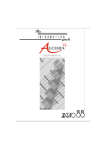
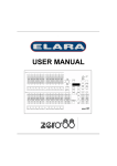
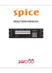
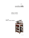
SPICE RACK DIMMER
OPERATING MANUAL
SPICE RACK DIMMER
OPERATING MANUAL
This equipment is designed for
professional stage lighting control only,
and is unsuitable for any other
purpose. It should only be used by, or
under the supervision of, an
appropriately qualified or trained
person.
Zero 88 Lighting Ltd. reserves the right
to make changes to the equipment
described in this manual without prior
notice. E & OE.
Issue 2 - December 2004
WARNING
DISCONNECT THE
DIMMER FROM THE
MAINS SUPPLY BEFORE
REMOVING ANY COVERS.
Manual Stock No. 73 - 854 - 00
© Zero 88 Lighting Ltd. 2004
Zero 88 Lighting Ltd.
Usk House
Llantarnam Park
Cwmbran
Gwent NP44 3HD
United Kingdom
Tel:
Fax:
e-mail:
Web:
+44 (0)1633 838088 *
+44 (0)1633 867880
[email protected]
www.zero88.com
* 24 hour answerphone
Spice Rack Dimmer 73-854-00 Issue 2
i
Contents
1. Introduction
This Manual
1-1
Overview
1-2
Front Panel Controls
1-2
2. Installation
Introduction
2-1
Mounting the Dimmer
2-2
Mains Connection
2-2
Socapex Connectors
2-3
Harting Connectors
2-3
DMX Connections
2-4
Chilli Network (Chillinet)
2-4
Network Connections
2-4
3. User Interface
Introduction
3-1
Main Screen
3-1
Menu Structure
3-2
Manual Control
3-2
Memories
3-4
Sequences
3-7
Preheat
3-9
Dimmer Laws
3-10
Topset
3-11
Reset Dimmer
3-12
DMX Controls
3-12
Security
3-15
Chilli Net
3-16
Area Control
3-16
Alarm Messages
3-17
4. Technical Specification
Introduction
4-1
Electrical
4-2
Mechanical
4-2
Environmental
4-2
EMC
4-2
ii
Spice Rack Dimmer 73-854-00 Issue 2
Figure 1 - 1: The Spice Rack Dimmer
Introduction
This Manual
Conventions
This manual describes the operation of
the Spice rack dimmer.
Throughout this manual the following
conventions are used.
This chapter contains a general
overview of the unit followed by a brief
description of the front panel controls
and displays.
References to front panel controls,
appear in capital letters, for example:
The Installation chapter provides
information on installing the dimmer
and connecting up the mains, loads,
DMX and Chilli network.
References to the LCD screen on the
control panel are shown as follows:
The User Interface chapter describes
all the various functions of the dimmer
which can be set up and operated via
the front panel controls.
The manual concludes with a chapter
on the technical specification of the
dimmer.
Spice Rack Dimmer 73-854-00 Issue 2
ENT key, ESC key.
DMX:
1
Temp: OK
References to fields which appear on
the LCD screen are shown in italics, for
example:
Manual Control, Set Chan Level etc.
1-1
Introduction
Overview
The Spice dimmer is a 12 channel 3U
high 19” rack mountable dimmer and is
available in the following versions:
•
•
12 x10 Amp Socapex
12 x10 Amp Harting
The channels may be patched as a
block or individually to the DMX.
Each channel has a manually
adjustable output level.
Each channel can be set to follow one
of four different dimming laws.
Figure 1 - 2: Control Panel
Preheat for individual channels can be
set to between 0% and 20%.
Each channel can be topsetted to limit
its maximum output level.
Front Panel Controls
Hash Key
Twelve programmable memories using
an output grab method.
The control panel provides the user
interface to the Spice rack dimmer.
Individual memories can be played
back, when required.
The following sections summarise the
front panel controls and displays.
The Hash key (#) is used to toggle the
channel level between 0% and 100%
in Manual Control or Edit memory.
Editable memory fade times and
channel levels.
LCD Display
Three programmable sequences using
the programmed memories.
The LCD Display comprises two lines
of 16 characters. For example:
DMX fail mode (DMX Hold, Fade to
Black or Fade to Memory).
Reset Dimmer function.
DMX status indication.
DMX:
1
Temp: OK
Numeric Keys
Stand alone or network modes.
Alarm state indication (if networked).
Star Key
Areas assignable to channels in
network mode, allowing memory and
sequence playback on an area basis.
The cursor keys (A> and B<) are used
to scroll across menus, select options
from a defined range, or increase or
decrease the value in a selected field.
Enter Key
The numeric keys (0 - 9) are used for
entering numerical data (eg channel
number, manual levels etc.)
Overheat indication and shutdown.
Cursor Keys
The Enter key (ENT) is used to confirm
numeric data entry, move down menu
structures, confirm operations etc.
Escape Key
The Escape key (ESC) is used to
escape from memory structures.
The Star key (*) is used to toggle the
back light on and off when the Main
Screen is displayed.
Lock function to prevent menu access.
1-2
Spice Rack Dimmer 73-854-00 Issue 2
Figure 2 - 1: The Spice Rack 12 Channel Dimmer
Installation
Introduction
This chapter deals with installing the
Spice rack dimmer and includes the
following sections:
•
•
•
•
•
•
•
Spice Rack Dimmer 73-854-00 Issue 2
Mounting the Dimmer
Mains Connection
Socapex Connections
Harting Connections
DMX Connection
Chilli Network (Chillinet)
Network Connections
2-1
Installation
Mounting the Dimmer
The Spice dimmer is 3U high and is
designed to be rack mounted into a
standard 19" cabinet using 4 x M6
Cage Nuts and 4 x M6 x16mm screws
(Figure 2-2). Rear support brackets are
available on request.
Ventilation must be provided in the
rack such that the dimmer can freely
draw air from its rear ventilation slots.
WARNING
INSUFFICIENT AIRFLOW
WILL CAUSE
OVERHEATING AND THE
DIMMER WILL SHUT
DOWN.
Figure 2- 2: Rack Mounting the Dimmer
Mains Connection
The mains supply to the dimmer is via
a 32 Amp 5 pin CEE17 connector
(see Figure 2 - 3)
Figure 2- 3: Mains Connector
2-2
Spice Rack Dimmer 73-854-00 Issue 2
Installation
Socapex Connectors
Two Socapex fixed sockets are
provided on the rear of the dimmer.
The left hand socket is wired for
channels 1 - 6; the right hand socket
for channels 7 - 12 (see figure 2 - 4).
For details of the pin numbers on the
Socapex connector see figure 2 - 5.
The following table shows the pin
connections of the Socapex connector.
Channel
Live
Neutral
Earth
1 (7)
1
2
13
2 (8)
3
4
14
3 (9)
5
6
15
4 (10)
7
8
16
5 (11)
9
10
17
6 (12)
11
12
18
Note - Pin 19 is not connected.
Figure 2 - 4: Rear Panel with Socapex Connectors
Figure 2 - 5: Socapex Connector Detail
Harting Connectors
Two Harting fixed sockets are provided
on the rear of the dimmer.
The left hand socket is wired for
channels 1 - 6; the right hand socket
for channels 7 - 12 (see figure 2 - 6).
For details of the pin numbers on the
Harting connector see figure 2 - 7.
The following table shows the pin
connections of the Harting connector.
Figure 2 - 6: Rear Panel with Harting Connectors
Channel
Live
Neutral
Earth
1 (7)
1
9
ET
2 (8)
2
10
ET
3 (9)
3
11
ET
4 (10)
4
12
ET
5 (11)
5
13
ET
6 (12)
6
14
ET
ET = Earth Terminal
Figure 2 - 7: Harting Connector Detail
Spice Rack Dimmer 73-854-00 Issue 2
2-3
Installation
DMX Connections
DMX input is through a 5 pin XLR
connector (Figure 2-8).
DMX output is through a 5 pin XLR
connector (Figure 2-8).
If DMX termination is required set the
Termination switch to the IN position
(Figure 2-8).
Chilli Network (Chillinet)
The following devices can be
connected to a Chilli Network system:
•
•
•
•
•
•
Chilli Pro Dimmer
Chilli Control Panel
Figure 2 - 8: Chilli Network and DMX Connectors
Chilli Master Controller
Chilli Netlink (hub)
Spice Rack Dimmer
Frog Box
Each device has a set of network
terminals or an RJ11 socket provided
for connection to the Chilli network.
The cable used to connect the various
devices in the network must be CAT 5
(100MHz) FTP cable.
All devices in the Chilli network must
be connected in serial. The devices in
the network can be wired in any order.
A network termination resistor must be
fitted at the two ends of the Chilli
network.
Network Connections
Figure 2 - 9: RJ11 Connections
Two RJ11 sockets are provided on the
Spice dimmer for connection to the
Chilli network (see Figure 2-8).
Wiring details for the RJ11 connector
are shown in Figure 2-9.
Note that only the central four pins
should be connected as shown.
2-4
Spice Rack Dimmer 73-854-00 Issue 2
User Interface
DMX Field
The DMX field shows the status of the
DMX input signal as follows.
Receiving valid DMX dimmer data :
“DMX: xxx” (DMX start address),or
“DMX: Patched”.
Receiving invalid DMX data:
“NOT DIMMER”.
DMX errors are occurring:
“DATA ERROR”.
Figure 3 - 1:Control Panel
No DMX data being received:
“NO DATA”.
DMX input disabled:
“DMX: DISABLED”
Introduction
This chapter describes all the various
dimmer functions.
Temp Field
The Temp field shows the temperature
sensor state as follows:
There are certain variations in menu
options and LCD displays between
stand alone and network modes.
Internal temperature sensor fault:
“Temp: No Val” (see note).
Main Screen
Normal operating temperature (<80 C)
“Temp: OK”.
The main screen is shown on the LCD
shortly after the dimmer is powered up,
and also if the user interface is not
used for a period of 30 seconds.
The data displayed on the main screen
depends on the operating mode and
state of the dimmer as follows:
In Stand Alone Mode - the screen
shows the DMX and Temp fields:
DMX:
1
Temp: OK
In Network Mode - the screen shows
the DMX and Chilli Net fields:
Hot (80 - 90 C):
“Temp: HOT”.
Overheat shutdown (> 95 C)
“Temp: FAIL”.
Chilli Net Field
If the dimmer is operating in network
mode, the second line of the LCD
shows “Chilli Net: xx”, where xx is the
dimmer number.
If the dimmer is in ‘dumb’ mode as a
result of conflicting dimmer numbers
on the network, the LCD will show:
“Chilli Net: CON”.
DMX:
1
Chilli Net: 12
In the Alarm State - the screen shows
the following:
DIMMER LOCKED
* ALARM ACTIVE *
Spice Rack Dimmer 73-854-00 Issue 2
Note
Temperature Field at Startup
The text “Temp: No Val” is displayed briefly
at startup as the dimmer is reading the
sensor. This is normal behaviour.
3-1
User Interface
Menu Structure
Manual Control
Set Channel Level
From the Main Screen, press the ENT
key to enter the menu structure.
Select the Manual Control option from
the top level menu options:
This option allows the user to set up a
manual control level between 0 - 100%
for each of the dimmer channels.
The menu structure is cyclic and the
cursor keys are used for navigation.
After selecting a top level menu option,
press the ENT key to enter the
corresponding sub-menu.
Hitting the ESC key on a screen
generally returns to the menu level
above the current one, except where
specifically stated in this manual.
The top level menu options are:
•
•
•
•
•
•
•
•
•
•
•
Manual Control
Memories
Sequences
Preheat
<Manual Control>
Press the ENT key to enter the Manual
Control menu.
Select the Set Chan Level option from
the menu:
<Set Chan Level>
The following options are available:
•
•
Press the ENT key to enter the menu.
Set Chan Level
Set All Chans
Use the cursor keys to scroll between
the options.
Press the ENT key to enter the menu
for the selected option.
Press the ESC key to return to the
Manual Control screen.
Stand Alone Mode - the LCD shows:
Channel: xx
Level: xxx
On entering this screen, a cursor is
shown in the Channel field.
The channel number defaults to 1.
Dimmer Laws
Topset
Reset Dimmer
DMX Controls
Security
Chilli Net
Area Control
When there are other menu options
available at the same level < and >
symbols will appear at the left and right
hand sides of the LCD. For example:
Network Mode - the LCD shows:
(Axx)Channel: xx
Level: xxx
On entering this screen, a cursor is
shown in the Channel field.
The channel number defaults to 1.
The area number (Axx) shows the area
that the dimmer channel is assigned to
and is for information only.
<Manual Control>
In Stand Alone or Network Mode,
individual channel levels can then be
adjusted using the numeric keypad or
cursor keys as follows:
3-2
Spice Rack Dimmer 73-854-00 Issue 2
User Interface
Numeric Keypad
When cursor is in the Channel field,
enter the channel number using the
numeric keys then press the ENT key.
The manual control level for the
channel is shown in the Level field and
the cursor moves to the Level field.
When cursor is in the Level field, enter
the required level (0 – 100) using the
numeric keys then press the ENT key.
The output of the dimmer channel
matches the level entered, the cursor
returns to the Channel field.
Cursor Keys
When cursor is in the Channel field,
press the A> key to increase the
channel number by 1, press the B< key
to decrease the channel number by 1.
As the channel number changes, the
corresponding manual control level is
shown in the Level field.
Press the ENT key. The cursor moves
to the Level field which shows the
corresponding manual control level.
Set All Channels
Set All Channels
Stand Alone Mode - Allows the user
to set a manual control level for all the
channels on the dimmer in a single
operation.
Network Mode - allows the user to set
a manual control level for all the
channels in a specified area on the
dimmer in a single operation.
Select the Set All Chans option from
the menu:
Select the Set All Chans option from
the menu:
<Set All Chans >
Press the ENT key. The LCD changes
to the following, with the cursor in the
Level field:
All Channels
Level: 0
Press the ENT key. The LCD changes
to the following, with the cursor in the
Area field:
Area:
Level:
1
0
Numeric Keypad
Numeric Keypad
Enter the required level (0 - 100%)
using the numeric keys and then press
the ENT key.
When the cursor is in the Area field,
enter the area number using the
numeric keys and press ENT key.
The outputs of all dimmer channels
matches the level entered.
If the area number is valid (ie the
dimmer has one or more channels
assigned to that area) the cursor
moves to the Level field.
The cursor remains in the Level field.
Cursor Keys
When the cursor is in the Level field,
pressing the A> key increases the level
by 1%, pressing the B< key decreases
it by 1%.
Press the A> key to increase the level
by 1%; press the B< to decrease the
level by 1%.
As the value in the Level field changes,
the output of the dimmer follows.
As the value in the Level field changes,
the output of all the dimmer channels
will change accordingly.
Pressing the ENT key will return the
cursor to the Channel field.
<Set All Chans >
Press the ESC key to return to the
Set All Chans screen.
Pushing the ESC key at any point on
this screen will return the screen to the
Set Chan Level.
Note - Using the # Key
The # key can be used as a quick method of
setting the manual control levels to full or off.
With the cursor in the Channel field, the #
key acts as a channel level toggle. The first
push will take it 100%, the second push will
take it 0% etc. The Level field shows the
current value (0% or 100%), but the cursor
remains in the Channel field.
When the cursor is in the Level field,
enter the required level (0 - 100%)
using the numeric keys and then press
the ENT key.
The outputs of all relevant dimmer
channels matches the level entered.
The cursor returns to the Area field.
Cursor Keys
Use the cursor keys to select the area
required.
Press the ENT key. The cursor moves
to the Level field.
Press the A> key to increase the level
by 1%; press the B< to decrease the
level by 1%.
As the value in the Level field changes,
the output of all the relevant dimmer
channels will change accordingly.
Press the ENT key to return the cursor
to the Area field.
Press the ESC key to return to the
Set Area Chans screen.
With the cursor in the Level field, the # key
acts as a channel level toggle. The first push
will take it 100% , the second push will take
it 0% etc.
Spice Rack Dimmer 73-854-00 Issue 2
3-3
User Interface
Memories
Record Memory
Record Memory
The Spice rack dimmer can be
programmed with up to 12 memories.
Stand Alone Mode - This option
allows the user to store the current
output levels in one of the 12
memories in the dimmer.
Network Mode - This option allows the
user to store the current output levels
in one of the 12 memories in the
dimmer. Only the levels of the dimmer
channels assigned to the specified
area are recorded into the memory.
The memories are programmed by
grabbing the current outputs.
The programmed memories can then
be played back, when required.
The fade time can also be adjusted, if
required, during this operation.
The channel levels and fade times for
programmed memories can be edited.
It is recommended that when recording
memories, the topset level for all
channels is set to 100%.
A Clear Memories function is also
provided under this menu option.
Select the Record Memory option from
the Memories menu. The LCD shows:
In Network Mode - memories are
recorded, played back, edited and
cleared on an area basis.
< Record Memory>
Press the ENT key, the LCD shows:
Memory Options
Select the Memories option from the
top level options menu:
<
Memories
>
Record Memory
xx
The cursor appears in the memory
number field (xx). Unprogrammed
memories are indicated by an ‘*’ next
to the memory number.
Press the ENT key to enter the
Memories menu.
Use the numeric keys or cursor keys to
select the required memory (1 - 12).
The folllowing options are available:
Press the ENT key to confirm the
memory selection. The LCD will show
the following:
•
•
•
•
Record Memory
Play Memory
Clear Memories
Edit Memory
Use the cursor keys to scroll between
the options, then press the ENT key to
enter the selected option.
Memory:
xx
Fade Time: xx
The Memory field is for information
only and is not editable. The cursor
appears in the Fade Time field.
Use the numeric keypad or cursor keys
to adjust the fade time as required
(1 - 60 seconds).
Press the ENT key to save the fade
time to the memory.
The dimmer will then grab the current
output levels and store them in the
selected memory.
The LCD screen will show the following
message for 1 second, and then return
to the Record Memory screen.
Memory xx
Saved
The fade time can also be adjusted, if
required during this operation.
It is recommended that when recording
memories, the topset level for all
channels is set to 100%.
Select the Record Memory option from
the Memories menu. The LCD shows:
< Record Memory>
Press the ENT key. The LCD shows
the following with the cursor in the
Area field:
Area:
Memory:
1
xx
Enter the required area number using
the numeric keys or cursor keys, then
press the ENT key. If the area is valid,
the cursor moves to the Memory field.
Use the numeric keys or cursor keys to
select the required memory (1 - 12).
Unprogrammed memories have an ‘*’
next to the memory number.
Press the ENT key to confirm the
memory selection. The LCD shows:
Area xx Mem xx
Fade Time: xx
The Area and Mem fields are for
information only. The cursor appears in
the Fade Time field.
Use the numeric keypad or cursor keys
to adjust the fade time as required
(1 - 60 seconds).
Press the ENT key to save the fade
time to the memory.
The dimmer will then grab the current
output levels for the selected area and
store them in the selected memory.
The LCD screen will show the following
message for 1 second, and then return
to the Record Memory screen.
Area xx Mem xx
Saved
3-4
Spice Rack Dimmer 73-854-00 Issue 2
User Interface
Play Memory
Play Memory
Clear Memories
Stand Alone Mode - This option
allows the user to playback (output)
one of the 12 memories programmed
in the dimmer.
Network Mode - This option allows the
user to playback (output) one of the 12
memories programmed in the dimmer,
or any other dimmer on the network,
on an area basis.
Stand Alone Mode - This option
allows the user to clear all the 12
memories in the dimmer.
Select the Play Memory option from
the Memories menu. The LCD shows:
<
Play Memory >
Select the Play Memory option from
the Memories menu. The LCD shows:
<
Play Memory >
Press the ENT key, the LCD shows:
Playback Memory
xx
The cursor appears in the memory
number field (xx). If a memory is
currently being output, then that
number is displayed in the field.
Use the numeric keys or cursor keys to
select a memory to be output (0 - 12).
Press the ENT key to confirm the
memory number selection.
The dimmer performs the following:
Memory Zero - The outputs fade to
those in memory zero in 3 seconds,
and replace any previous memory or
sequence being output.
Programmed Memory - The outputs
fade to those in the selected memory
in the memory’s fade time, and replace
any previous memory or sequence
being output.
Unprogrammed Memory - The
outputs do not change.
The LCD returns to the Play Memory
screen.
Note - Memory Zero
Memory Zero is a fixed, non-editable
memory, with a fade time of 3 seconds and
all channels programmed at 0%.
Note - Memory Playback
Stand Alone Mode - A dimmer can only
play back one memory at a time.
Network Mode - A dimmer can only play
back one memory per area at a time, but
may play back up to ten different memories if
they are all in different areas.
Press the ENT key. The LCD shows
the following with the cursor in the
Area field:
Area:
Memory:
1
xx
Enter the required area number using
the numeric keys or cursor keys, then
press the ENT key.
If the area number is valid, the cursor
moves to the Memory field.
If a memory for the selected area is
currently being output from the
dimmer, then that number is displayed.
Use the numeric keys or cursor keys to
select a memory to be output (0 - 12).
Press the ENT key to confirm the
memory number selection.
The dimmer sends out the
corresponding Play Memory/Area
message onto the network.
If the dimmer has one or more
channels assigned to the specified
area it performs the following:
Memory Zero - The outputs fade to
zero in 3 seconds, and replace any
previous memory or sequence being
output for the selected area .
Programmed Memory - The outputs
fade to those in the selected memory
in the memory’s fade time, and replace
any previous memory or sequence
being output for the selected area.
Unprogrammed Memory - The
outputs do not change.
The LCD returns to the Play Memory
screen.
Spice Rack Dimmer 73-854-00 Issue 2
Select the Clear Memories option from
the Memories menu. The LCD shows:
<Clear Memories>
Press the ENT key, the LCD shows:
Press ENT key to
clear memories
Press the ENT key to clear all the
memories and any programmed
sequences in the dimmer.
The LCD returns to the Memories
screen.
Clear Memories
Network Mode - This option allows the
user to clear all the 12 memories for a
specified area in the dimmer.
Select the Clear Memories option from
the Memories menu. The LCD shows:
<Clear Memories>
Press the ENT key, the LCD shows:
Area: 1
ENT to clear
The cursor appears in the Area field.
Use the numeric or cursor keys to
select the required area number (0-10),
then press the ENT key.
Area 0: This is a special case. The
dimmer will clear all stored memories
for all areas, and all programmed
sequences on the dimmer.
Area 1 -10: The dimmer will clear all
the stored memories for the selected
area, and any programmed sequences
for the selected area on the dimmer.
The LCD returns to the Memories
screen.
3-5
User Interface
Edit Memory
Edit Memory
Stand Alone Mode - This option
allows the user to edit the channel
values and fade time of a programmed
memory stored on the dimmer.
Network Mode - This option allows the
user to edit the channel values and
fade time of a programmed memory for
a selected area stored on the dimmer.
Press the ESC key. The LCD shows:
Select the Edit Memory option from the
Memories menu. The LCD shows:
Select the Edit Memory option from the
Memories menu. The LCD shows:
The Area and Memory fields are for
information only and are not editable.
The cursor appears in the Fade Time
field.
<
Edit Memory >
Press the ENT key, the LCD shows:
Edit Memory
XX
The cursor appears in the memory
number field (xx). Unprogrammed
memories are indicated by an ‘*’.
Use the numeric keys or cursor keys to
select the required memory (1-12),
then press the ENT key to confirm.
If the memory is programmed - The
dimmer outputs the selected memory
and the LCD shows the following:
Channel: 1
Level: xxx
The cursor is displayed in the Channel
field. The Level field shows the
programmed value for the channel.
Adjust the level of each channel as
required. This operation uses the same
user interface as the Set Channel
Level function in Manual Control.
Press the ESC key. The LCD shows:
Memory:
xx
Fade Time: xx
The Memory field is for information
only. The cursor appears in the Fade
Time field.
Use the numeric keypad or cursor keys
to adjust the fade time as required
(1 - 60 seconds).
<
Edit Memory >
Press the ENT key, the LCD shows:
Area:
1
Memory: xx
The cursor appears in the Area field.
Enter the required area number using
the numeric keys or cursor keys, then
press the ENT key.
If the area number is valid, the cursor
moves to the Memory field.
Area xx Mem xx
Fade Time: xx
Use the numeric keypad or cursor keys
to adjust the fade time as required
(1 - 60 seconds).
Press the ENT key to save the fade
time and the channel levels into the
memory.
The LCD screen will show the following
message for 1 second, and then return
to the Edit Memory screen.
Area xx Mem xx
Saved
Use the numeric keys or cursor keys to
select the required memory (1 - 12),
then press the ENT key to confirm.
The memory is removed from the
outputs.
If the memory for the chosen area is
programmed - The dimmer outputs
the selected memory and the LCD
shows the following:
If the memory for the chosen area is
unprogrammed - a star (*) is
displayed next to the memory number
and the memory cannot be edited.
(Axx)Channel: 1
Level: xxx
The area number field (Axx) is for
information only. The cursor is
displayed in the Channel field.
The Level field shows the programmed
value for that channel in the memory.
Adjust the level of each channel as
required. This operation uses the same
user interface as the Set Channel
Level function in Manual Control.
Note - Only those channels which
are assigned to the specified area
may be selected and edited.
Press the ENT key to save the fade
time and the channel levels into the
memory. The LCD screen shows the
following message for 1 second, and
then return to the Edit Memory screen.
Memory xx
Saved
The memory is removed from the
outputs.
3-6
Spice Rack Dimmer 73-854-00 Issue 2
User Interface
Sequences
Program Sequence
Program Sequence
The Spice rack dimmer can be
programmed with up to 3 different
sequences, each containing a
maximum of 12 steps.
Stand Alone Mode - This option
allows the user to program one of the
three sequences, using the
programmed memories in the dimmer.
Network Mode - This option allows the
user to program any of the three
sequences in the dimmer with
memories for a specific area.
In Stand Alone Mode - Each step in a
sequence is a reference to one of the
programmed memories in the dimmer.
Select the Program Sequence option
from the Sequences menu. The LCD
shows:
Select the Program Sequence option
from the Sequences menu. The LCD
shows:
In Network Mode - Each sequence is
associated with a specific area. Each
step in a sequence is a reference to a
memory in that area, but the memory
does not have to be programmed in
the dimmer itself.
Each sequence also has a cross-fade
and dwell time which determines how
the sequence runs:
X-Fade Time - The cross-fade time is
the time it takes to fade between two
steps in a sequence. The default
crossfade time is 1 second.
Dwell Time - The dwell time is the time
that the outputs remain on the values
in the current step of the sequence
before fading to the next step. The
default dwell time is 1 second.
Sequence Menu Options
Select the Sequences option from the
top level options menu:
<
Sequences
>
Press the ENT key to enter the
Sequences menu. The folllowing
options are available:
•
•
•
•
Program Sequence
Playback Sequence
Sequence Options
Clear Sequence
<
Program
Sequence
>
Press the ENT key, the LCD shows:
Select
Sequence: 1
The cursor appears in the sequence
number field. Use the numeric or
cursor keys to select the required
sequence number, then press the ENT
key. The LCD screen shows:
Seq 1 Step: 1
Memory: xx
The cursor appears in the Step field.
The Memory field shows the contents
of the step, if programmed, or “xx” if
the step is not programmed.
Select the first step in the sequence,
then press the ENT key. The cursor
moves to the Memory field.
Use the cursor keys to select one of
the programmed memories in the
dimmer. Press the ENT key to assign
the memory to the selected step. The
cursor returns to the Step field.
Use the cursor keys to select the next
step in the sequence, then press the
ENT key. The cursor moves to the
Memory field.
Use the cursor keys to select one of
the programmed memories in the
dimmer. Press the ENT key to assign
the memory to the selected step. The
cursor returns to the Step field.
Use the cursor keys to scroll between
the options.
Repeat the above process until all the
steps in the sequence have been
programmed (maximum of 12 steps).
Press the ENT key to enter the
selected option.
Press the ESC key to return to the
Select Sequence screen.
<
Program
Sequence
>
Press the ENT key, the LCD shows:
Sequence:
Area:
1
1
The cursor appears in the Sequence
field. Use the numeric or cursor keys to
select the required sequence number.
Press the ENT key.
The cursor moves to the Area field.
Use the numeric or cursor keys to
select the required area. Press the
ENT key. The LCD screen shows:
Seq 1 Step: 1
Memory: xx
The cursor appears in the Step field.
The Memory field shows the contents
of the step, if programmed, or “xx” if
not programmed.
Select the first step in the sequence,
then press the ENT key. The cursor
moves to the Memory field.
Use the cursor keys to select the
required memory number (1 - 12).
Press the ENT key to assign the
memory to the selected step. The
cursor returns to the Step field.
Use the cursor keys to select the next
step in the sequence, then press the
ENT key. The cursor moves to the
Memory field.
Use the cursor keys to select the
required memory number (1 - 12).
Press the ENT key to assign the
memory to the selected step. The
cursor returns to the Step field.
Repeat the above process until all the
steps in the sequence have been
programmed (maximum of 12 steps).
Press the ESC key to return to the
Sequence/Area screen.
Spice Rack Dimmer 73-854-00 Issue 2
3-7
User Interface
Playback Sequence
Playback Sequence
Sequence Options
Stand Alone Mode - This option
allows the user to playback any of the
three programmed sequences.
Network Mode - This option allows the
user to playback any of the three
programmed sequences.
This option allows the user to adjust
the crossfade and dwell times for the
sequences in the dimmer.
This option is used to start and stop
sequences running. Only one
sequence can be running at a time.
This option is used to start and stop
sequences running. Only one
sequence can be running at a time.
These times are global and apply to all
three sequences in the dimmer.
Select the Playback Sequence option
from the Sequences menu. The LCD
shows the following:
Select the Playback Sequence option
from the Sequences menu. The LCD
shows the following:
<
Playback
Sequence
>
Press the ENT key. If there is no
sequence currently running in the
dimmer, the LCD shows:
Sequence: 1
ENT to start
If sequence X is currently running in
the dimmer, the LCD shows:
Sequence: X
ENT to stop
<
Playback
Sequence
>
Select the Sequence Options option
from the Sequences menu. The LCD
shows:
<
Sequence
Options
>
Press the ENT key, the LCD shows:
Press the ENT key. If there is no
sequence currently running in the
dimmer, the LCD shows:
Sequence: 1
ENT to start
If sequence X is currently running in
the dimmer, the LCD shows:
Sequence: X
ENT to stop
X-Fade Time: xx
Dwell Time: xxx
The cursor appears in the X-Fade
Time field. Use the numeric keypad or
cursor keys to adjust the fade time as
required (range 1 - 60 seconds).
Press the ENT key to confirm the
crossfade time. The cursor moves to
the Dwell Time field.
A cursor appears in the Sequence
field. Use the cursor keys to select the
required sequence.
A cursor appears in the Sequence
field. Use the cursor keys to select the
required sequence.
Use the numeric keypad or cursor keys
to adjust the dwell time as required
(range 1 - 600 seconds).
The second line of the LCD changes
automatically to show the current state
of the selected sequence.
The second line of the LCD changes
automatically to show the current state
of the selected sequence.
Press the ENT key to confirm the dwell
time. The cursor moves to the X-Fade
Time field.
Starting a Sequence
Starting a Sequence
Press the ESC key to return to the
Sequence Options screen.
Select the required sequence using the
cursor keys, then press the ENT key.
Select the required sequence using the
cursor keys, then press the ENT key.
The sequence will start running and
replace any memory or sequence
which was previously being output.
Stopping a Sequence
The sequence will start running. The
dimmer sends out a start sequence
message onto the network, and then
play memory/area messages at the
appropriate times.
Select the sequence that is currently
running in the dimmer using the cursor
keys, then press the ENT key.
If a different sequence was running in
the dimmer it will be stopped and
replaced by the new one.
The sequence will stop running.
Starting a sequence in an area will also
replace any memory for that area
currently being output by the dimmer.
Press the ENT key, the LCD shows:
Stopping a Sequence
Use the cursor keys or numeric keys to
select the required sequence, then
press the ENT key, the LCD shows:
Select the sequence that is currently
running in the dimmer using the cursor
keys, then press the ENT key.
The sequence will stop running. The
dimmer sends out a stop sequence
message onto the network.
3-8
Clear Sequence
This option allows the user to clear any
of the sequences in the dimmer.
Select the Clear Sequence option from
the Sequences menu. The LCD shows:
<
Clear
Sequence
>
Select
Sequence: 1
Push ENT key to
clear sequence
Press the ENT key.The LCD returns to
the Clear Sequence screen.
Spice Rack Dimmer 73-854-00 Issue 2
User Interface
Preheat
Set Preheat
Cursor Keys
Select the Preheat option from the top
level menu options:
This option allows the user to set up a
preheat level (between 0 - 20%) for
each of the dimmer channels.
When the cursor is in the Channel
field, press the A> key to increase the
channel number by 1, press the B< key
to decrease the channel number by 1.
<
Preheat
>
Press the ENT key to enter the
Preheat menu. The following two
options are available:
•
•
Set Preheat
Clear Preheats
Select the Set Preheat option from the
menu:
< Set Preheat
>
Press the ENT key. The LCD changes
to the following:
Channel: xx
Level: xx
On entering this screen, a cursor is
shown in the Channel field. The
channel number defaults to 1.
There are 2 methods of operation
available on this screen :
Keypad Entry
When the cursor is in the Channel field
enter the channel number using the
numeric keys. Press the ENT key.
The preheat level for the selected
channel is shown in the Level field and
the cursor moves to the Level field.
When the cursor is in the Level field,
enter the required level using the
numeric keys. Press the ENT key. The
cursor returns to the Channel field.
As the channel number changes, the
corresponding preheat level is shown
in the Level field.
Press the ENT key. The cursor moves
to the Level field which shows the
preheat level.
When the cursor is in the Level field,
pressing the A> key increases the level
by 1%, pressing the B< key decreases
it by 1%.
The minimum preheat value is 0%, the
maximum value is 20%.
Pressing the ENT key will return the
cursor to the Channel field.
Pushing the ESC key at any point on
this screen will return the LCD to the
Set Preheat screen.
Clear Preheats
This option allows the user to clear the
preheat levels for all of the dimmer
channels to 0%.
Select the Clear Preheats option from
the menu:
<Clear Preheats>
Press the ENT key. The LCD changes
to the following:
Push ENT key to
Clear Preheats
Press the ENT key to set all the
channel preheat levels to 0%.
Spice Rack Dimmer 73-854-00 Issue 2
3-9
User Interface
Law Field
Dimmer Laws
Set Laws
The user can choose a dimmer law for
each of the dimmer channels. The
dimmer laws determine the relationship
between the control value and the
output value supplied to the lamp.
This option allows the user to set up
the dimmer law for each of the dimmer
channels.
Normal - The standard output of the
dimmer.
Linear - Suitable for most live or
theatrical situations.
Switch - Output switches from zero to
full when the input reaches 50%.
Square - For use with video cameras.
Select the Dimmer Laws option from
the top level menu options:
< Dimmer Laws
Channel: 10
Law: Normal*
Select the Set Laws option from the
menu:
Set Laws
The currently selected law for the
channel is indicated by a ‘*’, for
example:
>
Press the ENT key to enter the
Dimmer Laws menu.
<
When the cursor is in the Law field, the
cursor keys cycle through the laws.
>
Press the ENT key. The LCD changes
to the following:
Channel: xx
Law: xxxxxx
On entering this screen, a cursor is
shown in the Channel field. The
channel number defaults to 1.
The channel is selected using the
numeric keypad or cursor keys:
Channel Selection - Keypad Entry
Enter the required channel number
using the numeric keys, then press the
ENT key.
The law for the selected channel is
shown in the Law field and the cursor
moves to the Law field.
Channel Selection - Cursor Keys
Press the A> key to increase the
channel number by 1, press the B< key
to decrease the channel number by 1.
As the channel number changes, the
law for the channel is shown in the Law
field.
Press the ENT key. The cursor moves
to the Law field.
Pressing the ENT whilst in the Law
field returns the cursor to the Channel
field, and changes the law as shown.
Pressing the ESC key at any point on
this screen will return the LCD to the
Set Laws screen.
Reset Laws
This option allows the user to reset the
dimmer laws for all dimmer channels.
Select the Dimmer Laws option from
the top level menu options:
< Dimmer Laws
>
Press the ENT key to enter the
Dimmer Laws menu.
Select the Reset Laws option from the
menu:
<
Reset Laws
>
Press the ENT key. The LCD changes
to the following:
Push ENT key to
reset all laws
Press the ENT key to set the state of
all laws to normal. The following
screen will be shown for 1 second as a
confirmation.
Dimmer laws
reset to normal
The screen then returns to the top level
Dimmer Laws screen.
Pressing the ESC key at any point will
return the screen to the top level
Dimmer Laws screen and leave the
dimmer laws unchanged.
Figure 3 - 2: Dimmer Laws
3 - 10
Spice Rack Dimmer 73-854-00 Issue 2
User Interface
Topset
Set Topset
Cursor Keys
The Topset function is used to apply a
scaling factor to the final output level of
a channel, such that the input control
range gets compressed into a smaller
output range.
This option allows the user to set up a
topset level (between 0 - 100%) for
each of the dimmer channels.
When the cursor is in the Channel
field, pressing the A> key increments
the channel number, pressing the B<
key decrements the channel number.
For example - If the input level of a
channel is 80% and the Topset level of
the channel is 50%, the output level
will be 80% x 50% = 40%.
Topset Menu Options
Select the Topset option from the top
level menu options:
<
Topset
>
Press the ENT key to enter the Topset
menu. The following two options are
available:
•
•
Set Topset
Clear Topsets
Select the Set Topset option from the
menu:
<
Set Topset
>
Press the ENT key. The LCD changes
to the following:
Channel: xx
Level: xx
As the channel number changes, the
topset level is shown in the Level field.
Press the ENT key. The cursor moves
to the Level field which shows the
current topset level.
When the cursor is in the Level field,
pressing the A> key increases the level
by 1%, pressing the B< key decreases
it by 1%.
On entering this screen, a cursor is
shown in the Channel field. The
channel number defaults to 1.
Pressing the ENT key will return the
cursor to the Channel field.
There are 2 methods of operation
available on this screen :
Pushing the ESC key at any point on
this screen will return the LCD to the
Set Topset screen.
Keypad Entry
When the cursor is in the Channel
field, enter the channel number using
the numeric keys. Press the ENT key.
The topset level for the selected
channel is shown in the Level field and
the cursor moves to the Level field.
When the cursor is in the Level field,
enter the required level using the
numeric keys. Press the ENT key. The
cursor returns to the Channel field.
Clear Topsets
This option allows the user to clear
(reset) the topset levels for all of the
dimmer channels to 100%.
Select the Clear Topsets option from
the menu:
<Clear Topsets >
Press the ENT key. The LCD changes
to the following:
Push ENT key to
Clear Topsets
Press the ENT key to set all the topset
levels to 100%.
Spice Rack Dimmer 73-854-00 Issue 2
3 - 11
User Interface
Reset Dimmer
DMX Controls
Set Start Address
This option allows the user to reset the
dimmer to its default settings which are
defined as follows:
This option allows the user to set the
DMX start address for the dimmer,
patch individual channels to the DMX,
or reset the DMX patch to default.
This option allows the user to set a
DMX start address for the dimmer.
•
•
•
•
•
•
•
•
•
•
•
•
•
•
All dimming laws set to Normal.
Preheat for all channels off (0%).
All memories cleared.
This option also allows the user to
decide how the DMX input signal is
processed by the dimmer and set the
DMX fail mode, where applicable.
All memory fade times reset to 3s.
All sequences cleared.
DMX Controls Menu Options
Sequence crossfade reset to 1s.
Sequence dwell time reset to 1s.
Select the DMX Controls option from
the top level menu options:
DMX Fail mode - Fade to Black.
DMX Input Mode - HTP Mix.
All Manual Control levels set to 0%.
All Topset levels set to 100%.
Chillinet set to disabled.
All channels assigned to Area 1.
Select the Reset Dimmer option from
the top level options menu:
< Reset Dimmer >
Press the ENT key. The LCD shows:
Push ENT key to
Reset Dimmer
Press the ENT key to enter the DMX
Controls menu. The following options
are available:
•
•
•
•
Set Start Address
Set DMX Patch
Reset DMX Patch
DMX Input
The dimmer channels are then patched
automatically as a contiguous block
starting at the specified address.
Select the Set Start Address option
from the menu:
<
Set Start
Address
>
Press the ENT key. The LCD shows
the following with the cursor displayed
in the address field.
< DMX Controls >
DMX Address set to 1.
The range for the DMX start address
for the Spice dimmer is 1 - 501.
DMX Address
xxx
Enter the DMX address using the
numeric keys, or adjust using the
cursor keys, then press the ENT key.
This sets the start address for the
dimmer. The LCD screen pauses for
approximately 1 second and then
returns to the DMX Controls screen.
Pressing ESC on this screen leaves
the current DMX address unchanged
and return to the DMX Controls screen.
Press the ENT key. The LCD shows:
Push ENT key to
Confirm Reset
Press the ENT key to reset the dimmer
as described above. The LCD screen
returns to the main screen.
Pressing the ESC key on either of the
above two screens will return to the top
level menu Reset Dimmer screen.
3 - 12
Spice Rack Dimmer 73-854-00 Issue 2
User Interface
Set DMX Patch
Reset DMX Patch
DMX Input Modes
This option allows the user to set an
individual DMX address (1 - 512) for
each channel of the dimmer.
This option allows the user to reset the
start DMX address for the dimmer to
DMX channel 1.
Select the Set DMX Patch option from
the menu:
Select the Reset DMX Patch option
from the menu:
This option allows the user to enable or
disable the DMX input signal to the
dimmer without having to physically
disconnect the DMX cable.
<Set DMX Patch >
Press the ENT key. The LCD shows:
Channel: xx
DMX: xxx
The cursor appears in the Channel
field, which defaults to channel 1.
The corresponding DMX address
appears in the DMX field.
<
Reset DMX
Patch
>
Press the ENT key. The LCD shows:
Push ENT Key to
Reset DMX Patch
Press the ENT key to reset the DMX
patch. The LCD returns to the Reset
DMX Patch screen.
Keypad Entry
When the cursor is in the Channel
field, enter the channel number using
the numeric keys. Press the ENT key.
The DMX address for the channel is
shown in the DMX field; the cursor
moves to the DMX field.
When the cursor is in the DMX field,
enter the required address using the
numeric keys. Press the ENT key.
The dimmer channel is now patched to
the DMX address and the cursor
returns to the Channel field.
Cursor Keys
When the cursor is in the Channel
field, use the cursor keys to increase or
decrease the channel number.
Press the ENT key. The cursor moves
to the DMX field which shows the
current DMX address.
When the cursor is in the DMX field,
use the cursor keys to increase or
decrease the address, then press the
ENT key to patch the channel and
return the cursor to the Channel field.
Pushing the ESC key at any point on
this screen will return the LCD to the
Set DMX Patch screen.
Spice Rack Dimmer 73-854-00 Issue 2
When the DMX input is enabled, the
user can choose between two modes
of operation - HTP mixing or DMX
takes precedence.
If the dimmer is in Network Mode, the
user can also turn the selected DMX
Input mode for the dimmer, on or off for
each area defined on the dimmer.
If the DMX Input is enabled, the user
can select the DMX Fail Mode, that is,
choose what happens to the dimmer
outputs if the DMX input signal fails
(Hold DMX, Fade to Black or Fade to
Memory).
When the DMX Input is disabled, any
DMX input signal is ignored.
DMX Disabled
Any DMX Input is ignored by the
dimmer. The outputs are determined
by the manual control and memory or
sequence levels only, which are HTP
mixed together.
DMX HTP Mix
The DMX Input signal is mixed on a
HTP (highest takes precedence) basis
with the manual control and memory or
sequence levels to give the final output
levels.
DMX Takes Precedence
When the DMX Input signal is
available, it takes precedence over the
manual control and memory/sequence
levels - the outputs go to the DMX
Input levels.
When the DMX Input signal is not
available, the outputs are determined
by the manual control and memory or
sequence levels which are HTP mixed.
3 - 13
User Interface
DMX Input - Stand Alone
DMX Input - Network Mode
Select the DMX Input option from the
menu:
Select the DMX Input option from the
menu:
<
DMX Input
>
Press the ENT key. The LCD shows
the current setting for the dimmer, for
example:
< DMX DISABLED >
<
DMX Input
>
DMX Fail Mode
<
Hold DMX
>
Press the ENT key. The LCD shows
the current setting for the dimmer, for
example:
< DMX DISABLED >
Use the cursor keys to set the DMX
input to the required option (DMX
DISABLED, DMX HTP MIX, or DMX
PRECEDENCE).
Use the cursor keys to set the DMX
input to the required option (DMX
DISABLED, DMX HTP MIX or DMX
PRECEDENCE).
Press the ENT key to confirm the DMX
Input selection.
Press the ENT key to confirm the DMX
Input selection.
If DMX DISABLED was selected, the
LCD returns to the DMX Input screen,
otherwise the LCD shows:
If DMX DISABLED was selected, the
LCD returns to the DMX Input screen,
otherwise the LCD shows:
DMX FAIL MODE
<
Hold DMX
>
Select the required DMX fail Mode as
follows:
Hold DMX - Use cursor keys to select
this option. Press the ENT key.
Hold DMX - Use cursor keys to select
this option. Press the ENT key.
Fade to Black - Use cursor keys to
select this option. Press the ENT key.
Fade to Memory - Use cursor keys to
select this option. The LCD shows:
DMX Fail Mode
<Fade to Mem:xx>
This screen allows the use to turn the
selected DMX Input Mode on or off for
each area defined on the dimmer.
After selecting the fail mode, the LCD
returns to the DMX Input screen.
Fade to Memory - Use cursor keys to
select this option. The LCD shows:
If the selected area is valid, the cursor
moves to the DMX field.
After selecting the required fail mode
and pressing the ENT key, the LCD
returns to the DMX Input screen.
Select the required DMX Fail Mode for
the area as follows:
The cursor appears in the memory
number field. Use the numeric keys to
enter the required memory number,
then press the ENT key.
Fade to Black - Use cursor keys to
select this option. Press the ENT key.
Use the numeric keys to enter the
required memory number, then press
the ENT key.
This screen allows the user to set the
DMX Fail Mode for the dimmer.
1
ON
Area:
DMX:
The cursor is displayed in the Area
field. Use the numeric keys or cursor
keys to select an area, then press the
ENT key.
DMX FAIL MODE
<Fade to Mem:xx>
Press the ESC key to move on to the
DMX Fail Mode screen:
Use the cursor keys to select On or Off
as required. Press the ENT key. The
cursor returns to the Area field.
Repeat the operation for each area
defined on the dimmer.
Notes - DMX Fail Modes
Hold DMX - In HTP Mix mode, the last
DMX input levels are held in the dimmer and
mixed in as normal. In DMX Precedence
mode, the DMX inputs are removed from the
output calculations.
Fade To Black - The DMX Input values and
any memory or sequence being output are
faded to black (0%) over 3 seconds.
Fade To Memory - If the dimmer is not
outputting a memory or sequence, the
outputs fade to the specified backup
memory. If the dimmer is outputting the
backup memory, the outputs fade to that
memory. If the dimmer is outputting a
different memory or sequence, the outputs
will fade or snap to the memory or sequence.
Stand Alone Mode - the above statements
apply to all dimmer channels.
Network Mode - the above statements are
applied to the channels on an area basis,
since each area could be outputting a
different memory or sequence at the time of
DMX failure.
3 - 14
Spice Rack Dimmer 73-854-00 Issue 2
User Interface
Security
Locking the Dimmer
Unlocking the Dimmer
This option allows the user to lock the
dimmer, disabling all menu access.
Select the Security option from the top
level options menu:
If the dimmer is locked , the main
screen will be displayed on the LCD,
and all menu access will be disabled.
The dimmer is locked and unlocked
manually by entering a four digit code.
Global Unlock Code
There is also a global unlock code
which will unlock the Spice dimmer.
Contact Zero 88 or your dealer for
further information.
Networked Dimmers
A networked dimmer can be locked
locally as described in this section.
This will not prevent the dimmer from
being controlled from a master
controller or control panels connected
to the network.
A networked dimmer can also be
locked and unlocked from a Master
Controller.
<
Security
>
Press the ENT key. The LCD shows
the following screen, with the cursor in
the Code field:
Lock Dimmer
Code: xxxx
Use the numeric keypad to enter a 4
digit code (eg 2312) and then press the
ENT key. The following screen is
displayed on the LCD:
Confirm Code
Code: xxxx
Re-enter the same 4 digit code and
then press the ENT key to confirm.
If the codes match - the dimmer is
locked, the LCD returns to the main
screen, and all menu access is
disabled.
If the codes do not match - an error
message is displayed on the LCD for
one second, and then returns to the
Lock Dimmer screen above.
Pressing the ESC key at any time in
the above menu structure returns the
LCD to the Security screen.
Spice Rack Dimmer 73-854-00 Issue 2
If the ENT key is pushed in order to
gain access to the menus, the
following screen is displayed :
Dimmer Locked
Code: xxxx
Enter the 4 digit code using the
numeric keypad, and then press the
ENT key.
If the correct code is entered - the
dimmer is unlocked, and the LCD
displays the first screen in the top level
menu structure (Manual Control).
If an incorrect code is entered - an
error message is displayed for two
seconds and then the LCD returns to
the main screen.
Pushing the ESC key at any time in the
above screens will return the LCD to
the main screen.
Note - Unlocking the Dimmer
If the code to unlock the dimmer has been
forgotten, contact Zero 88 Technical Support
who will supply a master unlock code.
3 - 15
User Interface
Chilli Net
Area Control
Set Channel Area
This option puts the dimmer into
Network Mode so that it can be
controlled remotely by a Chilli Master
Controller, Chilli Control Panels or
other Chilli Pro or Spice dimmers on
the network via Chilli Net messages.
This option is only available when the
dimmer is in Network Mode.
This option allows the user to assign
each of the dimmer channels to an
Area (1 - 10).
This option allows the user to assign
an area to each of the dimmer
channels individually.
For the network to function correctly
each dimmer on the network must
have a unique dimmer number.
Dimmer channels may be assigned
individually or all the dimmer channels
may be assigned to the same area.
Select the Chilli Net option from the top
level options menu:
This allows the user to playback
memories and sequences across the
network on an area basis.
<
Chilli Net
>
Area Control Menu Options
Press the ENT key. The LCD shows
the following screen, with the cursor in
the State field:
Select the Area Control option from the
top level menu options:
< Area Control >
State: Disabled
Dimmer No: xxx
Use the scroll keys to select Enabled.
Press the ENT key to move the cursor
to the Dimmer No field:
State: Enabled
Dimmer No: xxx
Enter the dimmer number directly
using the numeric keys or adjust the
number using the scroll keys. Press
the ENT key to confirm.
The dimmer number is checked
against other dimmers on the network.
The LCD shows the following:
Verifying
Dimmer No
If the dimmer number is valid, the LCD
will show the following message before
returning to the Chilli Net screen:
Dimmer No
Accepted
If the dimmer number is already used
on the network, the LCD will show the
following message before returning to
state and dimmer number screen:
Dimmer No
Already Used
Press the ENT key to enter the Area
Control menu.
Select the Set Chan Area option from
the menu:
<Set Chan Area >
Press the ENT key. The LCD shows:
Channel:
Area:
1
1
On entering this screen, a cursor is
shown in the Channel field. The
channel number defaults to 1.
Numeric Keypad
When cursor is in the Channel field,
enter the channel number using the
numeric keys then press the ENT key.
The following options are available:
The area assigned to the channel is
shown in the Area field and the cursor
moves to the Area field.
•
•
When cursor is in the Area field, enter
the required area (1 – 10) using the
numeric keys then press the ENT key.
Set Chan Area
Set All Chans
The area is assigned and the cursor
returns to the Channel field.
Repeat operation for each channel.
Cursor Keys
When cursor is in the Channel field,
press the A> key to increase the
channel number by 1, press the B< key
to decrease the channel number by 1.
As the channel number changes, the
area assigned to the channel is
displayed in the Area field.
Press the ENT key. The cursor moves
to the Area field.
When the cursor is in the Area field,
use the cursor keys to select the
required area for the channel.
Press the ENT key to return the cursor
to the Channel field.
Repeat operation for each channel.
After completing the channel to area
assignments, press the ESC key to
return to the Set Chan Area screen.
3 - 16
Spice Rack Dimmer 73-854-00 Issue 2
User Interface
Set All Channels
Alarm Messages
This option allows the user to assign
an area to all the channels on the
dimmer in a single operation.
If the Spice dimmer is in Network Mode
it will respond to Alarm messages
received via the network.
Select the Set All Chans option from
the menu:
Alarm On Message
<Set All Chans >
Press the ENT key. The LCD changes
to the following, with the cursor in the
Area field:
All Channels
Area: 1
Numeric Keypad
When a networked dimmer receives an
Alarm On message:
•
•
•
•
Enter the required area number (1-10)
using the numeric keys and then press
the ENT key.
The LCD returns to the Set All Chans
screen.
The dimmer enters the Alarm State.
All channel output levels fade to
80% over a period of 1s (see note).
All menu access via the control
panel is disabled.
The LCD shows the following:
DIMMER LOCKED
* ALARM ACTIVE *
Alarm Off Message
Cursor Keys
When a networked dimmer receives an
Alarm Off message:
Press the A> key to increase the area
number by 1 press the B< to decrease
the area number by 1.
•
•
Use the cursor keys to select the
required area number, then press the
ENT key. The LCD returns to the Set
All Chans screen.
•
•
The dimmer exits the Alarm State.
All output channels fade to their
normal levels over a period of 1s.
All menu access via the control
panel is enabled.
The LCD shows the main screen.
Notes
Alarm State - Output Levels
When the dimmer is in the Alarm State, the
output levels are subject to topset, but not
temperature shutdown. Manual control
levels, memories, sequences, preheat and
DMX inputs do not have any contribution to
the final output levels.
Spice Rack Dimmer 73-854-00 Issue 2
3 - 17
User Interface
3 - 18
Spice Rack Dimmer 73-854-00 Issue 2
Figure 4 - 1: The Spice Rack 12 Channel Dimmer
Technical Specification
Introduction
This chapter provides the electrical,
mechanical, environmental and EMC
specifications for the Spice rack
dimmer.
Spice Rack Dimmer 73-854-00 Issue 2
4-1
Technical Specification
Electrical
Mechanical
EMC
Supply Voltage:
Size:
Low Voltage:
190V - 255V
482 x 420 x 132 mm.
EN60439-1 1994
Supply Frequency:
Weight:
EN60950
40 to 70 Hz
13 kg.
Emissions:
EN55022
Maximum Supply Current:
40A 3 phase star
Maximum Load per Channel
10A Max.
DMX Input:
USITT DMX512/1990
External switchable termination
EN55015:2000
Environmental
Operating Temperature Range:
EN61000-3-2
Immunity:
2 to 40 °C
EN61000-4-3
Humidity:
5 to 95% Non condensing
EN61000-4-4
EN61000-4-5
EN61000-4-6
EN61000-4-11AC
4-2
Spice Rack Dimmer 73-854-00 Issue 2
Zero 88 Lighting Ltd.
Usk House
Llantarnam Park
Cwmbran
Gwent NP44 3HD
United Kingdom
Tel:
Fax:
e-mail:
Web:
+44 (0)1633 838088 *
+44 (0)1633 867880
[email protected]
www.zero88.com
* 24 hour answerphone