1
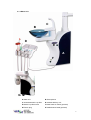
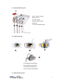
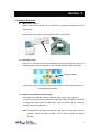
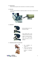
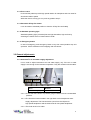
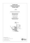
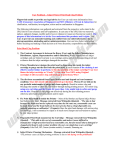
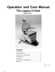
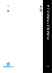
Grace
Chair-Mounted Dental Unit
QL-X5
Hanging / Over-the-patient
User’s Manual
Table of Contents
Section 1
3
1.1 General Information
3
1.2 Safety Information
3
1.3 Demolition and Dismantling
3
Section 2
4
2.1 Product Description
4
Section 3
9
3.1 General Operation
9
3.2 General Adjustments
11
Section 4
4.1 Hygiene and Maintenance
13
2
Section 1
1.1 General Information
Thank you for purchasing QL-X5 Dental Unit System. Prior using the product, please
read this USER MANUAL carefully and thoroughly as it provides details of proper
implementation of the operations, maintenances, and troubleshooting instructions.
QL-X5 is designed for use in dentistry sector according to ISO 7494 and ISO 6875.
Please keep this manual well preserved for future references.
1.2 Safety Information
1.2.1 Precautions and Warnings
- QL-X5 is not approved to be operated in areas where there is a risk of explosion.
- The user must be sure of the operational safety and proper condition of the unit
before using the unit.
- Stop working with damaged functional parts.
- Instrument tubing or any tubing may not be treated with adhesive.
- Instrument tubing must be regularly inspected and must be replaced immediately
if found damaged.
- After the end of the treatment, remove rotating instruments from turbines, straight
and contra-angle handpieces and treatments heads
- Never change the scaler tip without tool, to prevent injury and infection
- Before leaving the room, switch off the main switch
- QL-X5 conforms to applicable European Directives
- Electromagnetic fields may interfere with the functions of implanted systems, such
as pacemakers. Consult the patient before any treatment.
- The maximum load of 150 kg for the lifting movement and 100 kg for the
upholstery movement must not be exceeded.
- The maximum loading of the treatment tray is dependent on the instruments used.
Dentist’s treatment tray basically supports 2 kg and Assistant’s treatment tray 1
kg.
1.3 Demolition and Dismantling
Pursuant to Directive 2002/96/EC, this symbol
shows that the product must not be disposed of
as urban waste at the end of its operating life.
3
Section 2
2.1 Product description
2.1.1 Dental Chair
C
G
E
D
H
B
A
L
F
K
I
M
J
A Chair base / Utility Center
B Backrest
C Headrest
D Seat
E Armrest
F Multifunction foot control
G Massage button (optional)
H Backrest air bag button (optional)
I Floor junction box (optional)
J Umbilical
K Chair base
L Emergency stop button
M Mist/Steam drainage button
4
2.1.2 Water Unit
C
B
D
E
A
F
H
G
A Water unit
B Glass spittoon
C Infrared automatic cup filler
D Assistant delivery unit
E Manual cup filler button
F Water bottle air switch (optional)
G Electric plug
H Distilled water bottle (optional)
5
2.1.3 Assistant Delivery Unit
F
A QL-7 LED curing light
B HVE suction
E
C 3-way syringe
D Saliva ejector suction
E Keypad
F Tray & autoclavable pad
A B CD
2.1.4 Operating Light
C
B
A
D
A YS halogen operating light
B YF halogen operating light
C FARO EDI operating light
D G.com Polaris operating light
2.1.5 Dentist Delivery Unit
6
A
B
A Hanging delivery unit
B Panoramic X-ray film viewer
I
C
C Large tray & autoclavable pad
D Keypad
D
E 3-way syringe
J
F Turbine
G Scaler
H Low speed or micromotor
I Intraoral camera
E
J Oil cup
F GH
K Over-the-patient console
L Peri-apical X-ray film viewer
M QL-7 LED curing light
N Table & autoclavable pad
O Cart unit
P Table
K
J
O
P
L
D
I
H
J
G
E
F
M
N
7
2.1.6 Keypad
Assistant
Dentist
Seat ascending
Cup filler
Seat descending
Spittoon bowl flushing
Backrest descending
Assistance calling bell
Backrest ascending
Operating light
Chair seat from rinse position
Program 1
Return default position
Program 2
2.1.7 Multifunction foot control
A
Seat ascending
Program 1
Seat descending
Program 2
Backrest descending
Chair seat from rinse position
Backrest ascending
Return default position
Air
W
Water
8
Section 3
3.1 General Operation
3.1.1 Main power switch
Before switch ON the dental unit be sure that it is completely installed and in the
right position.
Before leaving the practice be sure that the power is turned OFF.
3.1.2 Program setting
Press S1 or S2 button till the LED indicator flash red light, adjust the chair to a
desired position and press again S1 or S2, the LED indicator turned yellow light.
LED light indicator
2
1
S1 and S2 program: the operating light will turned ON once the chair is positioned
into programmed position.
3.1.3 Cup filler and spittoon bowl flushing
Press spittoon bowl flushing button to activate water supply, rinsing the bowl.
Upon the cup is positioned, the infrared cup filler fills water automatically. However
to supply more water press cup filler button, even the patient can do it itself by
pressing manual cup filler button
Note: The spittoon flush is starting to feed the water when the “chair seat from rinse
position” button has been pressed. This is preset program as default
function.
9
3.1.4 Instruments
Refer to theirs respective user manual which is included in the package.
3.1.5 Armrest
Swiveled armrest outwards to enable the patient to climb onto or leave the seat
more easily.
3.1.6 Headrest
Pull the headrest out to suit
the patient’s height
Press locking knob on the
middle part and swivel head
support to desired position.
Press up to swivel head
support and down to swivel
headrest
3.1.7 Headrest position for wheelchairs
1
1.
Pull
completely
the
headrest out
2.
2
Rotate it 180° and slide
it back into the slot
pushing it completely
down.
10
3.1.8 Foot control
Push hard the pedal to provide high speed rotation for handpiece and vice versa for
slow down rotation speed.
While the chair is moving you can push any pedal to stop it.
3.1.9 Panoramic X-Ray film viewer
It can be rotate to a desired position to view the X-Ray film comfortably
3.1.10 Standard operating light
Standard operating light (YS model) has two light intensities, high and low by
switching the switch which is located at the handle.
3.1.11 Emergency button
In case of emergency push emergency button or any foot control pedal to stop unit
operation. Lift the assistant unit for stopping chair movement.
3.2 General adjustments
3.2.1 Instrument’s air and water supply adjustment
It’s no need to adjust instrument’s air and water supply, only if the air or water
supply is not enough for the instrument operation. They are located under the table.
A
W
G
A Air
W Water
G Pressure gauge
3.2.1.1 Ensure that the indicator of pressure gauge indicates at level 3 as standard
pressure.
3.2.1.2 The first three knobs located in the right back are for handpieces water
supply adjustment. The first two knobs (count from the left) are for
high-speed handpieces and the third knobs for low-speed handpieces..
3.2.1.3 The fourth knob is for scaler.
11
3.2.1.4 The three knobs after the fourth located are for handpieces air supply
adjustment. The first two knobs (count from the left) are for
high-speed handpieces and the third knobs for low-speed handpieces
3.2.1.5 Turn the knob clockwise to supply less air pressure or water, and
counterclockwise to supply more air pressure or water
Do not adjust the air and water supply by yourself, contact with your local
representative for the adjustments.
3.2.2 Infrared cup filler
3.2.2.1 Cup detection resetting. Cup filler detection default setting is for transparent
cup and must be resetting for opaque cup. Turn OFF main power, press cup
filler stand and at the same time turn ON main power, let water flow for 1-2
seconds and leave your hand from the cup filler, last put the opaque cup to
finish setting.
3.2.2.2 Amount of water adjustment
3.2.2.1 Remove the rear side cover carefully
3.2.2.2 Use a screwdriver to adjust the knob (as
shown on the picture)
3.2.2.3 Cover the cover by pushing it carefully
3.2.3 Backrest and seat movement speed adjustment
Contact with your local representative for the speed adjustment of backrest and
seat movement.
3.2.4 Delivery unit arm adjustment
Contact with your local representative for the loading capacity adjustment of
delivery unit arm.
12
Section 4
4.1 Hygiene and maintenance
4.1.1 After every patient
- Remove used aspiration tips/canulas
- Empty one glass of water (100-200 ml) with each suction hose by aspirating water
and air through the suction handpiece
- Clean the suction handpieces with Grace Disinfectant or autoclave them
- Using soft and clean cloth wipe with Grace Disinfectant the suction holders
- Disinfect with Grace Disinfectant:
Headrest
Armrests
Backrest
Patient seat
Operating light, except the plastic part of the cover
Instrument hoses
Delivery pad
Console table
- Autoclave curing light fiber optic light guide or remove the disposable cover
- Remove used disposable cover from the intraoral camera
- Autoclave turbines
- Autoclave 3-way syringe tip
- Remove suction handpiece filter
4.1.2 Weekly
- Clean the entire dental unit with Grace Disinfectant
- Clean plastic parts of the operating light with soft and clean cloth rinsed with water
- Clean the turbines hoses by pressing Ozone disinfection button
- Autoclave delivery and console silicone pad
- Press Mist/Steam drainage button 2 to 3 times
- Clean water bottle
4.1.3 Monthly
- Empty the oil collector cup and clean it
- Clean oil collector
Grace Disinfectant
13