1
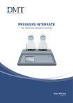
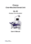
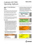
Operating Instructions
ISO 13485
Operating instructions for body-jet
Art. No. 500000
Art. No. 500000-1
Art. No. 500000-2
All rights to these operating instructions are reserved, in particular the rights of
reproduction, distribution and translation.
No part of these operating instructions may be reproduced in any form whatsoever
(photocopy, microfilm or any other process), or processed, reproduced or
distributed using electronic systems without the previous written permission of
human med AG.
The information contained in these operating instructions may be amended or supplemented without
previous notification and does not represent any obligation on the part of Human Med AG.
Printed by: Human Med AG
Printed in Germany
Copyright © Human Med AG; Wilhelm-Hennemann-Straße 9, 19061 Schwerin; 200/
Table of Contents
Title
General description of the body-jet
Page
2
Safety Information and Measures
Safety notations
Importance of the User Manual
Electrical safety
Safety instructions for the use of body-jet
Operational safety
Safety measures
3
3
4
5
5
5
Control Elements and Symbols
6
Description of applicator-system and suction cannula
12
Working with the body-jet
1) Insertion of the pressure container
2) Inserting the suction bag and connecting the suction hose
3) Connecting the applicator system to the liquid bags
4) Attachment of the suctio n cannula
5) Starting up the pressure generation and suction units
6) Operation
7) End of the operation
13
16
21
22
23
24
26
After the Operation
27
Installation of the body-jet
29
Environment
Operation conditions
Installation instructions
Troubleshooting
31
Reprocessing the reusable suction cannulas
34
Maintenance, Customer Service, Warranty
36
Technical Data/ technical description
38
These operating instructions constitute a part of the body-jet device and must
be kept in an easily accessible place in order that they may be consulted at any
time by operating staff.
Rev 11/2007
1 von 38
Description of the body-jet
The body-jet device was specially developed for the field of aesthetic plastic surgery, and in
particular, for liposuction (fat extraction). For this purpose the method of water-jet-assisted
liposuction (WAL) was developed by our company in cooperation with experienced doctors in
the field of aesthetic plastic surgery.
In contrast to traditional methods in which the tumescence solution is introduced into the body
and then removed by suction after a reaction time of up to one hour, the WAL method involves
the sucking off of fat cells in parallel with their detachment by a water jet.
The key feature of the method is the newly-developed applicator system.
In terms of its construction and method of operation this new applicator is comparable to the
helix hydro-jet applicator.
1. The liquid is transported from the container via the pressure generation unit through a
capillary tube to a stainless steel capillary with a nozzle, which is introduced into the patient.
2. The pressure generation device produces a pulsating water jet at a pressure of up to 110 bar.
This water jet escapes from the nozzle head of the nozzle capillary in the form of a flat angle
fanned jet.
3. The stainless steel capillary is integrated into a hand piece.
4. An infiltration or suction cannula may be attached to this hand piece according to choice.
5. The water jet detaches the fat cells from the connective tissue.
The fat cells and flushing solution are simultaneously sucked off by the suction cannula via the
suction tube into the aspiration container.
The suction process is achieved by an integrated suction system.
Devices belonging to these construction series comply with the stipulations of Regulation
93/42/EWG as well as the German Medical Product Law. Certification of our company in
accordance with DIN EN ISO 13485 as well as Appendix II of Regulation 93/42/EWG is a
guarantee that all provisions of Regulation 93/42/EWG and the German Medical Product Law
regarding the development, production, final control and marketing of body-jet devices and their
accessories are complied with.
Rev 11/2007
2 von 38
Safety Information and Measures
Safety notations
WARNING!
The WARNING! safety indication refers to a risk of personal injury.
CAUTION!
The CAUTION! safety indication refers to a risk of damage to property.
ATTENTION:
The ATTENTION! safety indication refers to a risk which can cause
equipment to become unserviceable.
Compliance with safety information
Appropriate application of and compliance with the safety information makes a
considerable contribution to the safety of the user, patients, and environment.
Safety of equipment and instruments
body-jet devices comply with all relevant and generally accepted engineering practices as well
as with the applicable occupational protection and accident prevention regulations.
Contribution of medical personnel to safety
Working with medical equipment is basically associated with certain risks to medical personnel
and patients. Risks cannot be entirely eliminated by design measures alone. Safety does not
depend solely on the equipment but depends to a large extent on factors influenced by you.
These factors are dealt with in the safety information in this chapter.
Safety and equipment use
This User Manual is an integral part of the body-jet. All users should be familiar
with the instructions in the Manual. Maintain these instructions in the Manual. Maintain these
instructions in a secure but readily accessible location so that all users may reference it at any
time.Prior to using the system, reference published literature and/or perform trial test to establish
pressure settings for applications.
Importance of the User Manual and training of medical personnel
Who should read
this User Manual?
The User Manual forms an important part of the safety concept of the unit.
Therefore everyone who is concerned with
•
preparing,
•
adjusting,
•
operating,
•
disassembling, as well as
•
cleaning and disinfecting
the unit ( including other associated equipment ) and instruments as applicable should read the
User Manual and the instructions for using the instruments.
Please pay partic ular attention to the safety instructions in each chapter.
Rev 11/2007
3 von 38
Training
WARNING! The equipment must be used only by medical professionals who have been
appropriately trained (In-Serviced) by human med .
Training must be carried out only by personnel who are suitable on the basis of their knowledge
and practical experience. Human med is not responsible for damage caused by user error.
In the event of uncertainties or if you have any questions, please contact human med. We will
be glad to give you further assistance and will be pleased to receive your suggestions concerning
this User Manual.
Electrical safety and electromagnetic compatibility
The device must be connected to an earthed mains supply in accordance with DIN VDE 0107.
This device has been tested for immunity to interference and for electromagnetic compatibility by an
accredited laboratory and the results lie within the limit values for medical electrical equipment as defined
in standard IEC 60601-1-2: 2001. Provided this device is correctly installed and is functioning properly it
is thus adequately immune to interference and cannot interfere with other devices. An exception to this is
the interaction with HF surgical devices since these do not always comply with the limit values of
standard IEC 60601-1-2.
When using the body-jet device in conjunction with HF surgical appliances manufactured before
09.11.1992 a minimum distance of 2 m must be ensured between the body-jet and the HF
surgical appliance as well as the HF surgical leads.
When using the body-jet device in conjunction with HF surgical appliances or laser cutting
devices it is essential that priority is given to the safety stipulations pertaining to these devices.
Prevention of electric shock
Leakage current
The equipment conforms to the requirements of “Type BF applied part”.
Power cord and power socket outlet
WARNING! The supply voltage must be identical to the voltage stated on the nameplate.
Connect the unit to a ground outlet. Use only the human med ag power cord or an equivalent
power cord.
Inspecting the equipment
WARNING! Inspect the equipment ( the unit including detachable components such as cords/
cables and the foot pedal) for damage or being compromised after each use. Do not use damaged
or compromised equipment. Please contact customer or technical service for replacement parts or
servicing. For the safety of medical personnel and patients, never attempt repairs.
Any modification to the equipment will invalidate liability on the part of human med.
Rev 11/2007
4 von 38
Safety instructions for the use of body-jet
It should be observed that the direct water jet may be dangerous due to its possible cutting action
depending on the pressure setting. Damage may be inflicted on eyes and skin should they come into
contact.
The following general safety regulations must be strictly observed:
-
All persons operating the device must receive prior instruction and be
acquainted with pressure and suction parameters.
-
The foot pedal must not be operated prior to use of the device.
-
When using the handpiece, care must be taken to ensure that the water jet is
only directed towards the area being operated on.
-
The capillary tube must not be bent
Operational safety:
Initial operation of the device is only permitted by professional staff previously instructed by
Human med ag.
The device may only be used after:
•
•
•
ready-to-use delivery of the device by the service team of human med AG
undertaking all safety measures,
mastering functional procedures and operation of the device in the event of malfunctioning.
All persons operating the device are fully responsible for observing all safety measures necessary
to ensure that the patient, the doctor- in-charge and all other persons present are not exposed to
danger during operation of the device.
Safety features:
Safe and reliable operation of the device is ensured by a series of built- in safety features. Pressure
build-up is only possible after an audible click indicating correct insertion of the pressure
container.
The device is designed so as to eliminate serious operational errors.
The disposable applicators are designed in such a way that resterilization is not possible.
A non-return valve shuts off the liquid flow when the foot pedal is not activated.
Contraindications:
The Body-jet , the WAL applicator system and the body-jet cannulas are not approved for intracardial use.
The operating instructions contain additional important information which should
be observed when operating the body-jet device.
Rev 11/2007
5 von 38
Control Elements and Symbols
Control elements of the membrane keypad
(1) Vacuum-manometer
The selected suction pressure is shown on the manometer
(2) Memory -display of the weighing- system
The display indicates the total liquid consumption of liquid used ( See page 16 and 17 )
(3) Display shows the amount of liquid used during the current suction sequence
( See page 16 and 17 )
(4) MEM –button in order to activate the weighing-system ( See page 16 and 17 )
(5) VACUUM-button The suction unit is turned on and off using the button
(6) STOP-button is for emergency stop
(7) Display The preselected pressure range is shown in this display.
(8) + and – button Select the pressure range ( RANGE 1 to 5 ) using the buttons
(9) The pressure generation unit is activated by pressing this ON/OFF button
(10) PUMP button to removel the pressure container ( See Page 18 )
Rev 11/2007
6 von 38
Control elements at the front, on the left and to the right
(1) socket for the pressure
container
1
(2) suction connector (see page 12)
to connecting the vakuum hose
2
3
5
5
4
6
6
(3) Sealing cap to the sealing the pressure container socket
(4) rotary switch
The desired suction pressure may be selected by means of this rotary switch.
(5) vacuum hose together with an angular connecting piece and plug connector
For connecting from suction container to the suction connector of the body-jet
(6) Suction container a suction bag must be inserted in each suction container
Rev 11/2007
7 von 38
(7) suction bag with angle connector
Manufacturer Serres Oy, FIN
7
Control elements on the back of the device
2
1
3
(1) body-jet power switch On / Off.
(2) Connection for the weighing system
The weighing system measures the liquid consumption during the operation.
Rev 11/2007
8 von 38
(3) Type label with the following symbols and their significance
Note symbol
This symbol indicates that the operating instructions and other relevant
instructions must be read before the device is put into operation.
This symbol indicates that the device has an application section of type BF and fulfils the
applicable safety requirements of IEC 60601-1.
This symbol indicates that the date of manufacture of the device is shown here.
This symbol indicates that the product conforms to the specifications of European Directive
93/42/EEC for medical products and that the manufacturer operates a quality assurance system
monitored by certification agency number 0482.
Rev 11/2007
9 von 38
4
5
(4) Symbol for handling the device during transport
ATTENTION! The device must not be transported outside the OP area with liquid bags
attached.
(5) Suspension facility for the liquid bags (with integrated weighing system)
ATTENTION! Maximum volume of the bags on the suspension facility: 7000 ml in total
(6) Removable rack with the bag suspension facility
ATTENTION! The connector for the weighing system must
be unscrewed before removing the rack
6
Rev 11/2007
10 von 38
7
8
7
8
9
(7) Symbol for foot-switch connection
This symbol indicates that only a foot switch may be connected at the connection marked with
this symbol.
ATTENTION! Only the supplied foot switches MGF 1Ö/1S-MED-AP from Steute
Medizintechnik may be connected.
(8) Foot-switch connection
The foot switches connected here are used for activating the set water pressure.
(9) Power connection
Connect the body-jet to a correctly installed grounded contact socket outlet using only the
original powercable or equivalent power cable. The power cable must bear the national test
symbol.
(10) Foot-switch holder
Place the foot-switch in the pedal holder when transporting or shutting down the body-jet.
10
10
Rev 11/2007
11 von 38
Sterile single-use WAL applicator system
F
(A) Hand-piece with the jet
capillary tube for introducing the
liquid for the detachment of fat cells.
Also deployable as a filtration
cannula
D
E
C
(B) Transfer set with two supply
lines for the simultaneous
connection of two liquid bags
B
A
(C) Pressure container with a
piston for generating the preselected liquid pressure for optimum
detachment of fat cells
(D) PA tube for transporting the pressurized liquid to the jet capillary
(E) Tube clamp for the liquid bag supply lines
(F) Puncture cannula with a protection cap attached to the liquid bag supply lines
Hand-pieces with suction cannula
B
A
(A) Suction cannulas are available with a wide variety of suction hole arrangements
(see product range)
(B) Bypass hole for activating and terminating the suction procedure by closing and opening the
hole
Rev 11/2007
12 von 38
Working with the body-jet
1. Insertion of the pressure container
A) Remove the applicator system from the sterile package.
Only use applicators from undamaged packages!
Remove the sealing cap from the pressure
container socket by turning it in the
anticlockwise direction.
Insert the pressure container in the socket
provided.
1
CAUTION:
The pressure line (rigid PA tube,1)
must point upwards whereas
the suction lines (flexible PVC tube,2)
must point downwards.
2
B) Bring the pressure container from the park position into the operating position by applying
slight pressure on the pressure container with the ball of the thumb.
Rev 11/2007
13 von 38
C) The pressure container is then engaged by applying gentle pressure with the thumb.
CAUTION: If the pressure container is not correctly engaged, it is not possible
to build-up pressure!
D) Now screw on the sealing cap hand-tight in the clockwise direction.
Rev 11/2007
14 von 38
2) Insertion of the suction bag and connection of the suction tube
Two suction containers of identical design and mode of operation are provided on the left and
right- hand side of the body-jet device for accepting suction bags.
CAUTION: Each suction container (A) must be connected to the suction connector (G) located
on the respective side of the device via an angular connecting piece (E), a suction tube with an
Overflow Protection (D) and a plug connector (F).
The required suction tubes together with an Overflow Protection, an angular connecting piece and
plug connector are supplied with the device.
C
D
G
F
E
K
B
A
B
REMARK: The suction container are only intended for use with suction bags. The proper
function of the suction by the body-jet can only be guaranteed , when 3000 ml suction bags with
an angular connecting piece manufactured by SERRES OY,FIN are used.
These may be obtained from human med or other supplier.
CAUTION! Don’t connect the suction-tube of the WAL-applicator into the suction connector(G)!
Ø A suction bag must be inserted in each suction container:
A) Unfold the suction bag and place it into the suction container.
B) Turn on the vacuum-pump.
Rev 11/2007
15 von 38
C) Insert the lid of the suction bag by using
vacuum, close the angle connector(K) with your
finger and simultaneously push the suction bag
lightly from the middle of the lid. The lid of the
suction bag must be flushly seated in the suction
container without leakage.
D) Turn off the vacuum-pump.
CAUTION! As both suction containers function in parallel it is necessary to close off the suction tube
connector at the patient (C) end attached to one of the suction bags by means of a sealing cap (L).
For this purpose it is first necessary to remove
the angle connector (K) from one of the two
suction bags in use.
L
K
The sealing cap (L) must then be pressed into the opening of the patient connector (C).
L
L
C
Rev 11/2007
16 von 38
Ø Turn on the vacuum-pump.
Check that the desired vacuum is established and the bag is fully inflated by closing
the angle connector of the unsealed suction bag.
Ø The suction tube (M) of the body-jet WAL applicator system must be firmly pushed
onto the angle connector (K) of the unsealed suction bag.
M
K
The suction system is now ready for use.
Rev 11/2007
17 von 38
Ø Connecting the applicator system to the second suction bag:
Each suction bag is fitted with an integrated overflow valve which interrupts the suction procedure when
the suction bag is full.
For this reason the applicator system should be connected up to the suction bag in the second aspirator in
good time. Before doing so, the filled suction bag must first be sealed.
M
K
C
•
Pull off the suction tube M with the angle
connector (K) of the full suction bag.
•
Seal off the patient connector (C) using the
sealing cap L as already described under 1.
.
Remove the sealing cap (L) from the suction bag of the second suction container and insert the angle
connecor (K) in the suction tube of the WAL-applicator in the patient opening (C) of the suction bag.
L
C
Rev 11/2007
M
K
C
18 von 38
Ø Removal and replacement of the suction bag
If both suction bags become full of liquid during an operation, it is necessary to replace one or both
suction bags.
•
•
•
Pull off the suction tube (M) with the angle connector (K) from the PATIENT conector of full
suction bag.
Close off the patient connector by means of the sealing cap L as already described under 1.
Remove the suction bag from the aspirator using the grip N.
M
L
•
K
C
N
Insert a new suction bag as described under 1.
Ø Disposal of the filled suction bags
CAUTION! The liquid suctioned off may contain germs harmful to the health.
The filled suction bags including the suctioned off liquid must be disposed of strictly in
accordance with the statutory hygiene regulations.
The bags must be discarded in secure waste containers for infectious waste marked as hazardous
waste. Details can be found in the hygiene plan of the hospital concerned.
Rev 11/2007
19 von 38
3. Connecting the applicator system to the liquid bags
A) The liquid containers must be hung on the rack, one container per hook.
CAUTION: maximum container weight = 3500 g
If bottles or canisters are used, these must be properly vented.
(insert a vent cannula)
We recommend the use of liquid bags only.
B) The applicator system is connected to the liquid bags via the transfer set.
One delivery tube (a) must be closed
using the tube clamp.
a
Remove the protection cap from
the puncture spike of delivery tube
(b) and insert the spike cannula
in the liquid container to be used first.
b
a
Rev 11/2007
20 von 38
Open the tube clamp on delivery tube (a)
in order to vent the tube system.
b
a
As soon as the delivery tube "a" is completely
filled with liquid the delivery tube is again
closed using the tube clamp.
The delivery tube "a" may now be inserted into
the second liquid container, if available.
First remove the protection cap from the
puncture cannula.
b
a
c
c
By opening and closing the tube clamps it is possible to select the liquid bag intended for
treatment.
4) Attachment of the suction cannula
B
A
Attach the suction cannula (A) required for the
particular application to the jet handpiece (B).
Caution! The supplied cannulas are sterile!
Rev 11/2007
Recommendation: apply silicon spray to the
inside of the cannula (A) attachment before use.
This is necessary to assemble the cannula to the
hand-piece (B) of the WAL applicator system.
21 von 38
4. Starting up the pressure generation and suction units
A) Turn on the body-jet device by pressing the mains rocker switch on the back of the device.
B) The pressure generation unit is activated by
pressing the ON/OFF switch on the PRESSURE
control panel
The green LED flashes
C) Select the pressure range ( RANGE 1 to 5 ) using
the +/- buttons.
The preselected pressure range is shown in the lefthand display.
Rev 11/2007
22 von 38
D) The suction unit is turned on and off
using the ON/OFF VACUUM button.
The desired suction pressure may be selected
in the range of 0 to minus 800 mbar by
means of the rotary switch (1) on the front of
the device.
1
The selected suction pressure is shown on
the manometer.
Rev 11/2007
23 von 38
E) In the event of a fault the suction
and pressure generation units may
be switched to EMERGENCY STOP
using the STOP button.
CAUTION!
Reactivation of the device after
EMERGENCY STOP is only possible by
pressing the power switch on the back of
the device.
6. Operation
Following a prick incision the suction cannula is inserted in the skin opening to the fatty tissue to be
extracted.
By actuating one of the two foot switches the pressure generation unit is started and the water jet
necessary to detach the fat cells is generated.
The required suction is realized by opening and closing the bypass opening in the suction cannula
handpiece.
The liquid consumption during the
operation is shown in the lower
right-hand display.
In order to activate this display it is necessary
to press the MEM button prior to the
operation.
Rev 11/2007
24 von 38
By pressing and quickly releasing the MEM
button once, the lower right-hand display is
reset to ZERO. The liquid consumption so far
is stored as a memory value and indicated in
the right-hand upper display.
This procedure may be repeated as often as required. The right-hand upper display then indicates the total
liquid consumption whereas the right-hand lower display always shows the amount of liquid used during
the current suction sequence.
By pressing the MEM button for
three seconds all consumption displays are reset to
ZERO.
This should always be done when connecting
up new liquid containers during one and the
same treatment.
Rev 11/2007
25 von 38
7. End of the operation
A) Switch off the pressure generation unit.
B) Remove the sealing cap.
C) Remove the pressure container by simultaneously pressing the unlo cking button
EJECT PUMP . This procedure may take up to 5 seconds.
D) Clamp the liquid delivery tubes and cut off the delivery system above the pressure container.
E) Remove the resterilizable suction cannula handpiece from the jet handpiece.
Rev 11/2007
26 von 38
After Operation
1. Discard the single-use applicator system !
CAUTION! The system may contain germs harmful to the health.
The single -use applicator system must be disposed of strictly in accordance with the statutory hygiene
regulations.
Used systems must be discarded in locked waste containers for infectious waste marked as hazardous
waste. Details can be found in the hygiene plan of the hospital concerned.
2. Switch off the body-jet
3. Cleaning and disinfection of the body-jet and accessories
For cleaning and disinfecting the surfaces of the body-jet and accessories human med ag
recommends wiping with disinfectant. Use only disinfectants that conform to the national
standards of the particular country.
Instructions for cleaning and disinfection
Mix the disinfectant in the concentration specified by the manufacturer. Clean surfaces
contaminated with blood with warm water before using the disinfectant, otherwise it may be less
effective.
Wipe the surfaces ensuring that they are uniformly treated. Comply with the action time of the
disinfectant specified by the manufacturer.
body-jet device
Wipe the device with a soft cloth soaked in disinfectant.
WARNING! Ensure that you disconnect the equipment or equipment trolley from the power
supply before starting cleaning and disinfection. Unplug the power connector!
ATTENTION Do not use substances containing solvents.
WARNING! Moisture must not penetrate the equipment. Drain off any ingress of liquid
immediately. The equipment must be used again only when this liquid has completely
evaporated.
sealing cap from the pressure container socket
Wipe the sealing cap from the pressure container socket with a soft cloth soaked in disinfectant.
If necessary use a soft brush soaked in disinfectant in addition.
Refit the sealing cap on the container socket
Foot-switch, cable for foot-switch and power supply cable
Wipe the foot-switch, the foot-switch cable and the power supply cable with a cloth soaked in
disinfectant.
Rev 11/2007
27 von 38
4. Hang up the power cord and pedal in the positions provided.
5. Move the body -jet into its parking position.
6. Apply the wheel brakes.
Inspecting the equipment and accessories
WARNING! Inspect the equipment and the accessories (e.g. foot control, cable) for damage after
every period of use. You must not use a damaged equipment, a damaged equipment trolley or
damaged accessories. Exchange defective accessories. If the equipment or equipment trolley is
damaged, please contact our customer service. For your safety and that of patients, never attempt
to effect repairs yourself. Any modification will invalidate liability on the part of human med.
Environmental conditions for transport and storage
The body-jet device may be transported in the upright or lying position.
Storage of the device has to be in upright position.
Temperature - 30 °C to + 50 °C
Relative atmospheric humidity 10 % to 95 %
Rev 11/2007
28 von 38
Installation of the body-jet
Environment
Do not operate in explosion hazard areas
WARNING! Only use the equipment in rooms used for medical purposes. Do not operate the
equipment in an explosion hazard zone. For example the equipment should not be used in close
proximity of flammable anaesthetics, combustible and/or explosive disinfectants, etc.
Operating conditions
ATTENTION: Only operate the equipment within the temperature and atmospheric
ranges specified in Technical Data. If the stated tolerances are exceeded, the in-stalled
equipment may not function properly or be damaged/unserviceable.
Comply with all operating stipulations in Technical Data.
Ventilation
ATTENTION: Only use the equipment in an area in which air can freely circulate
around the system housing. Do not use the equipment in confined spaces.
Spillage of / Exposure to liquids
ATTENTION: The equipment is not entirely resistant to the penetration of liquid.
Therefore be careful not to spill liquids around or on the equipment.
Power cord and power socket outlet
WARNING! The supply voltage must be identical to the voltage stated on the name-plate.
Connect the unit to a ground outlet. Use only the human med ag power cord or an equivalent
power cord.
• Verify that the power cord and outlet receptacle are properly insulated and intact. Be sure that
the socket has three prongs. Do not connect the unit to the supply or use the unit if any defective
conditions are present and the situation can not be appropriately corrected.
• Route the power cord from the unit to the receptacle in such away so as to eliminate any
dangerous situation (e.g., tripping).
Installing the body-jet
• Place/maintain the body-jet on a stable, horizontal, and vibration- free surface.
• Direct sunlight on the unit should be avoided, in order to have adequate display legibility and
for thermal reasons.
• The back of the body-jet should be directed away from the operating field.
• Upon establishing a good location for the unit (keep in mind the electrical supply need), engage
the locking breaks on the rear wheels.
Preparations for use
The mains switch is located on the back of the device. Switching to „I“ turns on the device.
Switching to "0" turns the device off.
Rev 11/2007
29 von 38
Accessories / device combination:
The body-jet device must only be operated using WAL-applicator systems and canulas supplied
be the human med ag company. The currently valid accessory list shall apply.
CAUTION! Only the accessory parts stipulated by human med ag in these operating instructions
may be used for the body-jet.
This applies in particular for the following accessories:
•
•
•
•
Foot-switch with foot-switch cable
Suction container
Suction bag
Vacuum tube with overflow protection, an angular connecting piece and a plug connector for
connecting the suction container to the suction connection on the device
• Sealing cap of the pressure container holder
Any modification to the WAL applicator system, the cannulas or the device accessories will
result in exclusion of liability by human med ag.
It is permissible to connect the suction tube of the WAL applicator system to a different suction
system.
Other combinations of equipment are not permissible and will result in
exclusion of liability by human med ag.
Rev 11/2007
30 von 38
Troubleshooting in case of functional and operating faults
This list is intended to help users to trace the causes of functional faults and to clear them as far as
possible or to give more detailed information to the Service Department of human med AG.
Fault Description
No pressure build-up, no fluid comes out of the nozzle
Possible cause of fault
Instruction for elimination
1. The mains plug was not connected.
2. The power switch of the device was not “ON”.
3. The foot-switches were not
Check the connectors.
connected.
4. The “ON/OFF” button for
„pressure“ was not activated.
Activate the button „ON/OFF“.
The LED-lamp next to „ON“ has to blink
green.
5. The foot-switch was not pressed. Press the foot-switch.
6. The pressure container was not
Please follow the routine described on pages 13 to 14 of this
exactly inserted into the socked.
operating manual.
ATTENTION! You must check whether the piston of the
pressure container is still in the park position or not.
7. The sealing cap was not screwed
accordingly.
Screw the sealing cap following the
description on page 14.
ATTENTION! The cap has not to be
detached without counter-clockwise
rotation.
8.Fluid was not connected.
The puncture spikes of the Transfer set
should be connected with the liquid bag.
9.The tube clamp of the Transfer
set-supply line was not opened.
10.The air was not correctly
removed from the Transfer set.
Check the tube clamps and open the clamp of the fluid bag
intended for use.
Please check the connecting-routine for the applicator system
described on pages 19 to 20.
Despite checking all above mentioned items there is
no water out of the applicator system after pressing
the foot switch for 30 sec in RANGE 5.
Rev 11/2007
Please replace the applicator system.
31 von 38
Fault
Check / Clearance
No power supply after operating the switch
Power supply interrupted
ðCheck mains plug !
Very weak jet, poor jet profile
WAL applicator system blocked or faulty
ðChange WAL applicator system
Liquid on the floor under the device
WAL applicator system blocked or faulty
ðChange WAL applicator system
No suction or only weak suction with the suction
cannula
Suction bag not inserted correctly, or second
suction bag not closed, or suction tube not correctly
attached
ðCheck suction bag and suction tube
Suction cannula blocked
ðChange suction cannula
The pressure container of the applicator cannot be
removed in a way described on page 24 of this
operating manual.
- Generate a water jet in operation mode RANGE 5
for three seconds (see page 20 to 22)
- deactivate the foot-switch
- Twist off the sealing cap, activate the foot-switch
again.
- Switch off the pressure generation unit by pressing
the ON/OFF button 9 on the body-jet display (see
page 6 in this user manual).
- Remove the pressure container by
simultaneously pressing the unlocking button
EJECT PUMP . This procedure may take up to
5 seconds.
STOP fault message on the display and buzzer signal
STOP 00
Triggered by activation of the EMERGENCY OFF
button or the control pushbutton for overload on the
power module. This fault message is also triggered
by overloading of the geared motor.
WAL applicator system blocked or faulty
ðChange WAL applicator system
STOP 01
Not activated.
STOP 02
In event of non-compatibility of the nominal value
stored in the software for the pressure of the device
in range 0 (approaching the pump dead center
point)
Contact the responsible Technical Service.
Rev 11/2007
32 von 38
STOP 03
In event of non-compatibility of the nominal value
stored in the software for the pressure of the device
in range 1 - 5.
Contact the responsible Technical Service.
STOP 04
In event of non-compatibility of the maximum
voltage value for the device stored in the software
in the range 1 – 5.
Contact the responsible Technical Service.
STOP 05
In event of non-compatibility of the maximum
current value for the device stored in the
software in the range 1 – 5.
Contact the responsible Technical Service.
STOP 06
Exceeding of the limit value of the specified
voltage in the different ranges. Contact the
responsible Technical Service.
STOP 07
Exceeding of the limit value for the specified
current in the different ranges. This resulted in
overloading of the drive system. WAL
applicator system blocked or faulty.
First switch the device off and back on again via the
main switch.
If the fault message is displayed again
ðChange WAL applicator system
If the fault message is displayed once again
contact the responsible Technical Service.
CAUTION!
In the event of malfunctioning, operation of the device must be immediately terminated by
pressing the EMERGENCY OFF switch.
The manufacturer
human med AG
Wilhelm- Hennemann-Strass 9
19061 Schwerin
Tel.: +49 /(0)385 / 3957011
Fax.: +49/(0)385 / 3957010
must be notified of the fault.
Rev 11/2007
33 von 38
Reprocessing the reusable suction cannulas
ATTENTION!
Instruments containing aluminium are damaged by strongly alkaline (pH > 10) cleansing agents
or disinfectants.
Only cleaning agents recommended for anodized aluminium should be used. Please consult the
manufacturer of the instrument cleaning agent or disinfectant accordingly. At the end of this
section we list a number of instrument cleansing agents and disinfectants tested by our
company.
WARNING!
Cleaning and sterilization should only be carried out by trained staff in facilities specifically
intended for this purpose.
Restrictions regarding
repeated cleansing:
Frequent repeated cleansing has little effect on the suction cannulas.
The product service life is normally governed by wear and tear resulting from use.
Instructions:
Place of use:
Remove surface contamination using a disposable cloth / paper tissue.
Storage and transport:
Special care must be taken during transportation to ensure that the suction cannula nozzle is not
damaged.
It is recommended to reprocess the sucction cannulas immediately after use.
Precleansing:
Immerse in an enzymatic instrument cleaning solution (Helizyme, 1%, diluted with at most
lukewarm deionized water, for at least 5 minutes or even longer in the case of persistent or dried
contaminants).
Clean the internal cannula walls using a pipette brush (Ø ca. 4 mm) followed by flushing of the
cannula in the suction direction with deionized water and cleaning of the pipette brush also with
deionized water to remove visible contaminants.
Repeat this procedure until the flushing solution and the brush are free of visible contaminants.
The instrument cleansing solution must be replaced at least once a day, and more often in the
case of visible contamination.
Cleaning:
Fully immerse the suction cannulas in an instrument cleaning solution (Helizyme, 1%, diluted
with at most lukewarm deionized water, for 5 minutes).
Flush the suction cannula with instrument cleansing solution in the suction direction for 1
minute.
Flush the suction cannula with deionized water in the suction direction for 1 minute.
Disinfection:
Fully immerse the suction cannulas in an instrument disinfectant solution (Stabimed, 2 %,
diluted with deionized water, for 15 minutes).
Flush the suction cannulas with sterile deionized water for 1 minute.
Repeat the flushing procedure. The sterile deionized water must be replaced after each flushing
procedure.
Drying:
Dry the suction cannulas internally and externally using sterile compressed air.
Maintenance:
Apply a small quantity of surgical lubricant spray to the attachment point of the suction cannula.
Control and
examination:
Carry out a visible examination to check for damage and wear (firm seating of the suction tube
in the hand-piece and intactness of the nozzle tip of the suction cannula).
Packaging:
The cannulas must be single packed in sterile packages in accordance with EN 868. The
packages for the suction cannula must be sufficiently large to ensure that the package seal is not
under tension.
Sterilization:
Steam sterilization by means of the fractional vacuum technique at 121°C (250°F) for at least
15 minutes has been validated. Sterilization up to 135°C (275°F) has been tested to not have any
negative effects on the cannulas.
Validation of your sterilization process with sterilization temperatures higher than 121°C
(250°F) is necessary.
WARNING!
Check the sterilization protocol for compliance with the prescribed parameters.
Storage:
Store in a closed cupboard providing protection against dust and large humidity and temperature
fluctuations.
The shelf life is determined by the product specifications of the sterile packages used.
Rev 11/2007
34 von 38
The instructions outlined above have been validated by the medical product manufacturer as
being suitable for the preparation of the suction cannulas for reuse. The person responsible for
cleansing is obliged to ensure that the cleansing actually carried out with the equipment, materials
and staff deployed in the cleansing facility attains the desired results. As a guarantee of the latter,
validation and routine monitoring of the procedure are normally necessary. It is equally important
that any departure from the instructions provided must be carefully evaluated by the person
responsible for cleansing with regard to their effectiveness and possible disadvantageous
consequences.
Table1: List of the DGHM-listed instrument cleansing agents and disinfectants tested with
regard to material compatibility
Trade name
Manufacturer
Instrument cleansing agent
Helizyme
BBRAUN
Bodetex forte
MucadontZYMAKTIV
Instrument disinfection
Stabimed
Korsolex extra
Mucocit T
Disinfectant
BODE
Gigasept AF
A 20
A 10
Rev 11/2007
MERZ
BBRAUN
BODE
MERZ
SCHÜLKE &
MAYR
OROCHEMIE
OROCHEMIE
Remarks
enzymatic cleansing
agent
enzymatic cleansing
agent
aldehyde-free
aldehyde-free
aldehyde-free
aldehyde-free
35 von 38
Maintenance, Customer Service, Warranty, Disposal
Maintenance Authorized persons
Safety inspections, modifications and repairs may be undertaken only by human med or by
persons expressly authorized by human med AG. If unauthorized persons carry out modifications
repairs, human med AG accepts no responsibility and claims under warranty become void.
Safety inspections
The safety inspection represents a preventative maintenance, in which an authorized technician
checks whether the safety and serviceability of the equipment and the accessories are within a
specific, technical specification.
A safety inspection must be undertaken at least once a year.
Modifications and repairs
Modifications and repairs represent preventative maintenance. They must not impair the safety of
the equipment or equipment trolley and accessories for the patient, user and the environment.
This condition is met when changes to the structural and functional characteristics are not
detrimental to safety.
What safety checks must be undertaken?
The following safety checks are specified for this equipment:
• Equipment and accessories free from external damage.
• User manual provided.
• Inscriptions present and legible.
• Ground wire tested according to EN 60601-1.
• Leakage current measurement according to EN 60601-1.
• Function testing of power switch, display, easy removal of the pressure container, suction,
pressure stability, foot pedal
• As part of the safety check the general condition of the drive unit must be checked with regard
to wear. Wear of the crankshaft and the unlocking device must be assessed with particular care.
• The results of these safety checks must be entered in the medical product book .
If deficiencies are found during the safety checks which could endanger patients,
personnel or third parties, the equipment must not be used until these deficiencies
have been remedied by technical personnel.
Periodic maintenance
Maintenance is specified at least once a year. If maintenance is not carried out, errors can occur
which may result in danger. The maintenance includes a safety check.
Customer service
If you are interested in a maintenance contract, please contact human med ag or an authorized
distributor.
Do you have any questions concerning the equipment or instructions for use? Would you like
scientific publications from human med ag? If so, contact an human med ag. We will be glad to
provide further assistance.
Rev 11/2007
36 von 38
Warranty
The device and accessories must be checked for defects and transport damage immediately after
receipt. Claims for damages in this respect may only be asserted if the seller or transport
company is notified without delay. A damage report must be drawn up.
human med grants its customers a warranty for supplied body-jet devices in accordance with its
General Terms and Conditions from the time of delivery and initial familiarization. A warranty
over and above these conditions shall require the conclusion of a corresponding warranty
contract. To do this, contact the seller of the device.
The warranty covers the performance of any work that may arise in case of complaints relating to
the function of the device if these are verifiably caused by the manufacturer. No warranty will be
assumed for any faults arising due to wear and tear in use, incorrect use, technical interference
with the device, deliberate damage or damage caused by gross negligence.
Further claims, particularly claims for damages are excluded.
Disposal
The equipment can be disposed of at the end of their useful life as with normal electronic scrap.
Rev 11/2007
37 von 38
Technical data / technical description
Dimensions in cm:
54 (b) x 60 (d) x 178 (h)
Weight in kg:
46
Pressure generation:
Sterile pressure container with an electro-mechanical drive unit
Pressure range in bar:
30 to 110
Pressure settings:
adjustable in 5 stages: 30, 50, 70, 90 and 110 bar
- Preselection of pressure via a control panel
- Activation of pressure via a foot pedal
Suction unit:
integrated, adjustable from 0 to –800 mbar
Power supply:
Art.-no. 500000:
Art.-no. 500000-1:
Art.-no. 500000-2:
Applicators:
Sterile, disposable applicators,
Sterile, resterilizable cannulas
Nozzle diameter in µm:
300
Safety class according
to IEC 60601-1:
I
OP applicator type class:
BF
Approval certificates:
CE 0482
Hazard class according to
RL 93/42/EWG:
Class II a
230 V~, 6 A, 50 - 60 Hz
120 V~, 6 A,
60 Hz
100 V~, 10 A, 50 - 60 Hz
Environmental conditions for transport and storage
The body-jet device may be transported in the upright or lying position.
Storage of the device has to be in upright position.
Temperature - 30 °C to + 50 °C
Relative atmospheric humidity 10 % to 95 %
Environmental conditions for operation
Temperature + 10 °C to + 40 °C
Relative atmospheric humidity 30 % to 75 %, without condensation
Rev 11/2007
38 von 38