1
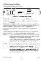
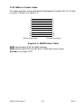
C.2.2 Daisy-Chain Cable
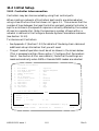
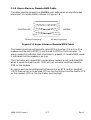
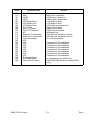
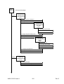
The cables used to daisy-chain a series of Controllers is shown in Figure
C-4.
Controller
Controller
1
2
3
4
5
7
20
22
1
2
3
4
5
7
20
22
25-way D-type plug
25-way D-type plug
Figure C-4 Daisy-Chain Cable
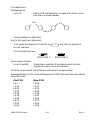
There are two modes of daisy-chaining that can be used with this cable:
User mode (VT100 operation)
CTS, DSR and DCD can be user-defined.
CTS must be defined as High to enable the remote Controller to
transmit if flow control is enabled.
RI will be Low until logon is requested when it will be raised, RI will
revert to Low when logon is released.
At the remote Controller RI must be defined as Low, CTS defined as
High.
NMS mode (network management protocol in use)
RI must be defined as Low.
Note: There is no flow control between Controllers. If flow control is
enabled RTS must be High for the Controller to transmit. A Controller will
not lower CTS if its buffer is full.
X450-312151 Issue 1
C-4
Rev.0