1
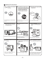
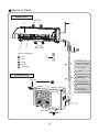
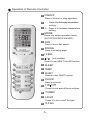
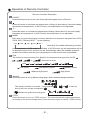
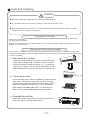
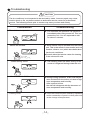
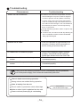
USER'S MANUAL
SYMPHONY SERIES
ASH-09AISR, ASH-09AISB, ASH-09AISW
ASH-13AISR, ASH-13AISB, ASH-13AISW
CONTENTS
Operation and Maintenance
■ Safety Precautions ..................................1
■ Name of Parts ......... ...............................4
■ Operation of Remote Controller ............................ 5
■ Emergency Operation ................................10
■ Care and Cleaning ...................................11
■ Troubleshooting ....................................14
■ Operation Tips .....................................17
Installation Service
■ Notices for Installation ................................19
■ Installation Drawing .................................22
■ Installation
. of Indoor Unit .................................23
■ Installation of Outdoor Unit ..........................26
■ Check after Installation and Operation Test ...............27
■ Installation and Maintenance of Healthy Filter(Optional) ........28
Never attempt.
Be sure to follow this instruction
The physical product may differ from the drawing in this manual for different display.
If there are some differences between them, please refer to the physical product as
the standard.
This appliance is not intended for use by persons (including children) with reduced
physical, sensory or mental capabilities or lack of experience and knowledge,
unless they have been given supervision or instruction concerning use of the appliance
by a person responsible for their safety.
Children should be supervised to ensure they are away from the appliance.
Do not dispose this product as unsorted municipal waste.
Collection of such waste separately for special treatment
is necessary.
Safety Precautions
Please read the following notices before operation.
WARNING
★If there's abnormal pheno-
★ Do not operate the air cond- ★ Do not cut off or damage the
menon (like smell of burning),
please cut off the power immediately and then contact with
authorized maintenance
center.
itioner with wet hands.
If this abnormal status is kept
on, air conditioner may be
damaged or even cause
electric shock or fire.
★ The special circuit must be
adopted for power supply to
avoid fire.
power cord or signal control
wire. If the power cord or signal
control wire of air conditioner
is damaged, please replace it by
the professional with specified
power cord.
Otherwise, it may cause electric
shock.
★ Please cut off the power supply ★ Do not damage the power
when the air conditioner won't be
used for an extended period of
time.
cord or use unspecified
power cord.
it may
Do not use octopus multipurpose
socket or mobile wiring board for
wire connection.
Otherwise, accumulated dust
may cause overheating, fire
and other accidents.
★ Before cleaning the air con- ★ Power supply should adopt
ditioner, please cut off the power. the special circuit with the protection of air switch and the capacity
must be sufficient. Pease do not
turn on or turn off the air conditioner
frequently .
cut off power
Y-type connection is adopted for the
power supply of this air conditioner.
If the power cord is damaged, it
must be replaced by the manufacturer, maintenance center or a
similarly qualified person to avoid
a hazard.
Otherwise, it will cause electric
shock or injury.
1
Otherwise, it may cause fire due to
overheating of power cord.
★ When the voltage is too high,
electric elements can be damaged
easily; if the voltage is too low, the
compressor will vibrate fiercely,
which may damage the cooling
system or compressor, and electric
components can't operate.
Safety Precautions
★ Always ensure effective ★
earthing.
For safety, be sure to turn
off the circuit beaker before
performing any maintenance
or cleaning or when the
product is not used for an
extended period of time.
★ Select the most appropriate
temperature.
Keep room about
5℃ cooler than
outside.
No earthing may cause electric
shock .
Accumulated dust may cause fire
or electric shock.
It can save electric energy.
★ Do not keep windows and
★Do not block the air inlet or
★ Keep combustible materials
doors open for a long time
during operation.
outlet.
It will result in insufficient performance. It will result in insufficient performance
and cause malfunctions.
at least 1m away from the
units .
It may cause f ire or explosion.
★ Install the outdoor unit firmly ★ Do not step on the top of the ★ Do not attempt to repair the
enough.
It may cause falling of the unit
and injury to the person.
outdoor unit or place heavy
things on it.
It may cause damage or injury.
2
air conditioner by yourself.
Incorrect repairs may cause electric
shock or fire. Please contact the
local authorised service center.
Safety Precautions
★ Do not cut off or damage the power cords or
control cords. If they are damaged, please
contact the dealer or qualified service
personnel
★ To change the airflow direction, adjust the vertical
and horizontal air flow direction by using the
remote controller.
Vertical Louver
Horizontal Louver
★ Do not insert your hands or objects into
the air in let or outlet.
★ Do not expose animals or plants directly to
the air flow .
It may cause an accident.
It may have a detrimental effect on them.
★ Do not expose yourself to cold air
for a long time.
directly
★ Do not use the unit for any other purpose , such
as preserving food or drying clothes.
It's not good for your health.
★ Do not splash water on the air conditioner .
★ Do not place
It may cause electric shock or malfunction.
It will cause CO toxicosis due to incomplete burning.
3
a burner near the air conditioner .
Name of Parts
Indoor unit
Air in
⑴
⑶
⑷
⑹
Air out
⑸
⑺
The icons displayed:
⑵
:Cool
:Dry
:Heat
⑴ Power cord
:Power
⑵ Remote controller
:Set temp.
⑶ Front panel
⑷ Filter
⑸ Horizontal louver
Outdoor unit
⑹ Wall pipe
Air in
⑺ Binding tape
⑻ Connection wires
⑼ Drain hose
⑻
⑽ Drain connector
⑼
Air out
⑽
4
Operation of Remote Controller
1
ON/OFF
Press it to start or stop operation.
2
- : Press it to decrease temperature
setting.
3
+ : Press it to increase temperature
setting.
4
1
3
2
MODE
Press it to select operation mode
(AUTO/COOL/DRY/FAN/HEAT).
5
FAN
6
SWING
Press it to set fan speed.
Press it set swing angle.
7
I FEEL
/
8
(not available)
Press it to set HEALTH or AIR function.
4
5
9
SLEEP
6
7
10
TEMP
8
9
11
QUIET
10
11
12
13
14
16
15
Press it to set QUIET function.
12
CLOCK
Press it set clock.
13
T-ON T-OFF
Press it to set auto-off /auto-on timer.
14
TURBO
15
LIGHT
Press it to turn on/off the light.
16
X-FAN
5
Operation of Remote Controller
Remote Controller Description
1 ON/OFF :
Press this button to turn on the unit .Press this button again to turn off the unit.
2
Press this button to decrease set temperature. Holding it down above 2 seconds rapidly
decreases set temperature. In AUTO mode, set temperature is not adjustable.
3
+:
Press this button to increase set temperature.Holding it down above 2 seconds rapidly
increases set temperature. In AUTO mode, set temperature is not adjustable.
4 MODE :
Each time you press this button,a mode is selected in a sequence that goes from AUTO,
COOL,DRY, FAN,and HEAT *, as the following:
AUTO
COOL
DRY
FAN
HEAT
*
*Note:Only for models with heating function.
After energization, AUTO mode is defaulted. In AUTO mode, the set temperature will not
be displayed on the LCD, and the unit will automatically select the suitable operation
mode in accordance with the room temperature to make indoor room comfortable.
5 FAN :
This button is used for setting Fan Speed in the sequence that goes from AUTO,
, then back to Auto.
,
,
to
,
Auto
Low speed
Low-Medium speed
Medium speed
Medium-High speed
6
High speed
SWING:
Press this button to set up &down swing angle, which circularly changes as below:
OFF
This remote controller is universal . If any command
the unit will carry out the command as
,
or
is sent out,
indicates the guide louver swings as:
7 I FEEL:
Press this button to turn on I FEEL function. The unit automatically adjust temperature
according to the sensed temperature. Press this button again to cancel I FEEL function.
6
Operation of Remote Controller
Remote Controller Description
8
/
Press this button to achieve the on and off of healthy and scavenging functions in
operation status.Press this button for the first time to start scavenging function;
LCD displays“ ”. Press the button for the second time to start healthy and scavenging
functions simultaneously; LCD displays“ ” and “ ” . Press this button for the third
time to quit healthy and scavenging functions simultaneously. Press the button for the
fourth time to start healthy function; LCD display “
”. Press this button again to repeat
the operation above.
9
●
●
●
●
●
SLEEP:
Press this button, can select Sleep 1 (
), Sleep 2 (
),Sleep 3 (
) and cancel
the Sleep,circulate between these, after electrified, Sleep Cancel is defaulted.
Sleep 1 is Sleep mode 1, in Cool, Dehumidify modes: sleep status after run for one hour, the
main unit setting temperature will increase 1 ℃,setting temperature increased 2℃, the unit will
run at this setting temperature; In Heat mode: sleep status after run for one hour, the setting
temperature will decrease 1 ℃, 2 hours, setting temperature will decrease 2 ℃, then the unit
will run at this setting temperature.
Sleep 2 is sleep mode 2, that is air conditioner will run according to the presetting a group of
sleep temperature curve.
Sleep 3- the sleep curve setting under Sleep mode by DIY:
(1) Under Sleep 3 mode, press "Turbo" button for a long time, remote control enters into user
individuation sleep setting status, at this time, the time of remote control will display "1hour ",
the setting temperature "88" will display the corresponding temperature of last setting sleep
curve and blink (The first entering will display according to the initial curve setting value of
original factory);
(2) Adjust "+" and "-" button, could change the corresponding setting temperature, after
adjusted, press "Trubo "button for confirmation;
(3) At this time, 1hour will be automatically increased at the timer postion on the remote
control, (that are "2hours " or "3hours " or "8hours "), the place of setting temperature "88"
will display the corresponding temperature of last setting sleep curve and blink;
(4) Repeat the above step (2) ~ (3) operation, until 8hours temperature setting finished,
sleep,curve setting finished, at this time, the remote control will resume the original timer
display;temperature display will resume to original setting temperature.
Sleep3- the sleep curve setting under Sleep mode by DIY could be inquired:
The user could accord to sleep curve setting method to inquire the presetting sleep curve,
enter into user individuation sleep setting status, but do not change the temperature, press
"Turbo" button directly for confirmation. Note: In the above presetting or enquiry procedure,
if continuously within10s, there is no button pressed, the sleep curve setting within
10s, there is no button pressed, the sleep curve setting status will be automatically
quit and resume to display the original displaying. In the presetting or enquiry procedure, press
"ON/OFF" button, "Mode" button, "Timer"button or "Sleep" button, the sleep curve setting
or enquiry status will quit similarly.
7
Operation of Remote Controller
10 TEMP:
Press this button, could select displaying the indoor setting temperature or indoor ambient
temperature.When the indoor unit firstly power on it will display the setting temperature,
if the temperature's displaying status is changed from other status to" ",displays the
ambient temperature, 5s later or within 5s, it receives other remote control signal that will
return to display the setting temperature. if the users haven't set up the temperature
displaying status,that will display the setting temperature.
11 QUIET:
Auto
Press this button, the Quiet status is under the Auto Quiet mode (display "
"signal )
and Quiet mode (display "
" singal) and Quiet OFF (there is no signal of "
"
displayed),after powered on, the Quiet OFF is defaulted.
12 CLOCK :
Press CLOCK button, blinking
. Within 5 seconds,pressing +or - button adjusts the
present time.Holding down either button above 2 seconds increases or decreases the
time by 1 minute every 0.5 second and then by 10 minutes every 0.5 second. During
blinking after setting, press CLOCK button again to confirm the setting,and then
will be constantly displayed.
13
T-ON T-OFF:
Press T-ON button to initiate the auto-ON timer. To cancel the auto-timer program, simply
press this button again.
After press of this button,
disappears and "ON "blinks .00:00 is displayed for ON time
setting. Within 5 seconds, press + or - button to adjust the time value. Every press of either
button changes the time setting by 1 minute. Holding down either button rapidly changes the
time setting by 1 minute and then 10 minutes. Within 5 Seconds after setting, press TIMER
ON button to confirm.
Press T-OFF button to initiate the auto-off timer. To cancel the auto-timer program, simply
press the button again.TIMER OFF setting is the same as TIMER ON.
14 TURBO:
Press this button to activate / deactivate the Turbo function which enables the unit to
reach the preset temperature in the shortest time. In COOL mode, the unit will blow strong
cooling air at super high fan speed. In HEAT mode, the unit will blow strong heating air
at super high fan speed.
15 LIGHT:
Press LIGHT button to turn on the display's light and press this button again to turn off
the display 's light. If the light is turned on ,
is displayed. If the light is turned off,
disappears.
16 X-FAN:
Pressing X-FAN button in COOL or DRY mode, the icon
is displayed and the indoor
fan will continue operation for 10 minutes in order to dry the indoor unit even though you
have turned off the unit.
After energization, X-FAN OFF is defaulted. X-FAN is not available in AUTO, FAN or
HEAT mode.
8
Operation of Remote Controller
17 Combination of "+" and "-" buttons: About lock
Press "+ " and "-" buttons simultaneously to lock or unlock the keypad. If the remote
controller is locked,
is displayed. In this case, pressing any button,
blinks
three times.
18 Combination of "MODE " and "-" buttons : About switch between Fahrenheit and centigrade
At unit OFF, press "MODE " and "- " buttons simultaneously to switch between ℃ and ℉ .
19 Combination of " TEMP " and "CLOCK" buttons : About Energy-saving Function
Press “TEMP” and “CLOCK” simultaneously in COOL mode to start energy-saving function.
Nixie tube on the remote controller displays “SE”. Repeat the operation to quit the function.
20 Combination of " TEMP " and "CLOCK" buttons : About 8℃ Heating Function
Press “TEMP” and “CLOCK” simultaneously in HEAT mode to start 8℃ Heating Function
Nixie tube on the remote controller displays “ ” and a selected temperature of “ 8℃”.
(46℉ if Fahrenheit is adopted). Repeat the operation to quit the function.
21 About Back-lighting Function
The unit lights for 4s when energizing for the first time, and 3s for later press.
Replacement of Batteries
1.Remove the battery cover plate from the rear of the remote controller.
(As shown in the figure)
2.Take out the old batteries.
3.Insert two new AAA1.5V dry batteries, and pay attention to the polarity.
4. Reinstall the battery cover plate.
★ Notes:
●
When replacing the batteries, do not use old or different types of batteries,
otherwise, it may cause malfunction.
●
●
●
●
If the remote controller will not be used for a long time, please
remove batteries to prevent batteries from leaking.
The operation should be performed in its receiving range.
It should be kept 1m away from the TV set or stereo sound sets.
If the remote controller does not operate normally, please take the
batteries out and reinsert them after 30 seconds.If it still can't operate properly,
replace the batteries.
9
Sketch map for
replacing batteries
Emergency Operation
Emergency Operation
When the remote controller is lost
or damaged, please use the manual switch
on the main unit. In that case, the unit will
operate in AUTO mode and the temperature
setting or fan speed can not be changed.
The manual switch can be operated as below:
Manual switch
●
Turn on the unit: Press AUTO/STOP button to
enter AUTO mode.
The microprocessor will select the mode
(COOL, HEAT, FAN) automatically according
to the room temperature for reaching comfortable
effect.
●
Turn off the unit: Press the AUTO/STOP button to
switch off the unit.
●
The operation mode is shown in the following table.
Mode
AUTO
AUTO
AUTO
●
Model
COOLING
HEAT PUMP
HEAT PUMP
Temperature setting
25℃ ( COOL,FAN)
25℃ ( COOL,FAN)
20℃ ( HEAT)
Airflow rate
AUTO
AUTO
AUTO
This switch is to be applied when the remote controller is missing.
10
Care and Cleaning
Caution
● Disconnect the power supply before cleaning and maintenance.
●
?
Do not splash water on the units for cleaning, as electric shocks may occur.
?
●
Wipe the units with a dry soft cloth, or a cloth slightly moistened with water or cleaner (not with
volatile liquid such as thinner or gasoline).
Cleaning the Front Panel
Remove the front panel. Dip a piece of cloth into the water colder than 45 ℃ and dry it . Then wipe
the dirty part of front panel.
Note: Do not immerse the front panel into water so as to protect microprocessor components and circuit
diagram on the front panel.
Cleaning the Air Filter (every 3 months)
Note: If the air conditioner operates under dusty environment, the frequency of cleaning air filter shall
increase correspondingly. When the filter is removed, do not touch the fins of the indoor unit with fingers
for fear of scalding.
① Take down the air filter
Press the clasp as shown by arrow (1) to loosen the
lower end of clasps until a sound of “crack” is heard;
press the clasp as shown by arrow(2)to open the
upper end of clasp; open the panel and then pull the
filter downward to remove it.(As shown in figa and b)
(Fig.a)
⑵
⑴
(Fig.b)
② Clean the air filter
Clean the filter with a vacuum cleaner or wash the filter
with water. If the filter is very dirty (such as oil stain),
please clean it with the mixture of warm water (<45℃)
and neutral abluent and then dry it up in the shade.
Note: Never use water above 45 ℃ to clean the air
filter as it may cause deformation or discoloration.
③ Reinstall the air filter
Install the air filter along arrow (1) direction and then
buckle the panel cover along arrow (2).
⑵
⑵
⑴
11
Care and Cleaning
Installation and Maintenance for Healthy filter
1. Press the clasp as shown by arrow (1) to loosen
the clasps at the lower end until a sound of “crack” is
heard; press the clasp as shown by arrow (2) to open
the clasps at the upper end; open the panel and then
pull the filter downward to remove it.
(As shown in fig a)
⑵
⑴
Fig a.
Fig b.
Air filter
2. Install the healthy filter on the air filter (as shown in
fig b). If the healthy filter fails to be installed on the
air filter, please install the healthy filter on the
front case(As shown in fig c).
3. Install the air filter along arrow (1) direction and
then buckle the panel cover along arrow (2).
(As shown in fig d)
Healthy filter
Healthy filter Install position
Fig c.
⑵
Fig d.
⑵
⑴
Clean and Maintenance for Healthy Filter
Please remove the healthy filter before cleaning and reinstall it well after cleaning
according to the installation instruction. Please note that the silver ion filter shall
NOT be washed by water. Active carbon filter, photocatalytic filter,LTC catalyst
and formaldehyde-killer filter can be washed by water, but shall not be scrubbed
with a brush or hard object. When washing is completed, dry the filter in shade rather
than wipe with a rag.
Service Life for Healthy Filter
The general service life for healthy filter is one year under normal operation. As to
silver ion filter, it is ineffective when the surface turns black(or green).
● This complementary instruction is only referred for the unit with healthy filter.The
graphs in this complementary instruction may be different from the actual product,
please refer to the actual product. Please refer to the actual delivery for the quantity of
healthy filter.
12
Care and Cleaning
Check before Use
①
Make sure that nothing obstructs the air inlet and air
outlet of indoor and outdoor units.
② Make sure there is effective grounding.
③ Make sure the batteries for remote controller are replaced.
④ Make sure the installation support for outdoor unit is in good condition. If it’s damaged,
please contact appointed maintenance center. If there is rust on the outdoor
unit, please apply some paint to the rusty spot to avoid spreading. BE CAREFUL
when painting!
Maintenance after Use
①
Disconnect the power for the air conditioner.
②
Clean the filter and the body of indoor and outdoor units.
③
Remove the dust and other objects on the outdoor unit.
④
Make sure the installation support for outdoor unit is in good condition.
If it’s damaged, please contact appointed maintenance center.
If there is rust on the outdoor unit, please apply some paint to the rusty
spot to avoid spreading. BE CAREFUL when painting.
⑤
Indoor and outdoor units can be wrapped by special protective bags to avoid rain
and dust getting into the units to erode them.
13
Troubleshooting
CAUTION
The air conditioner is not expected to be serviced by users. Incorrect repair may cause
electric shock or fire, so please contact an authorized service center for professional
service. The following checks prior to contact may save your time and money.
Phenomenon
Troubleshooting
The unit does not operate:
The unit does not operate if it is turned on
immediately after being turned off. This is to
protect the unit. You are expected to wait
for about 3 minutes.
●
Waiting
Odours are emitted:
●
Some odours may be emitted from the indoor
unit. This is the result of room smells (such as
furniture, tobacco, ect.) which have been taken
into the air conditioner.
● Consult
authorized service center for cleaning
if the odours still exist.
"Water flowing" noise:
Mist is emitted in COOL mode
Cracking noise:
The swishing noise like water flowing is the
sound of refrigerant flowing inside the unit.
●
● During
cooling operation, a thin mist may be
seen emitted from the indoor unit due to high
room temperature and humidity.
After a period of time,
the mist will disappear with the decrease of
room temperature and humidity.
● This is the sound of friction caused by expansion
and/or contraction of panel or other parts due
to the change of temperature.
14
Troubleshooting
Phenomenon
The unit can not be started up:
Troubleshooting
● Is the power cut off?
● Is the power plug loose? (If applicable)
● Is the circuit protection device tripped off?
● Is voltage higher or lower?
(Tested by professionals)
Breaking off
Cooling/Heating effect is poor:
● Is the TIMER correctly used?
● Is temperature setting appropriate?
● Is the inlet or outlet blocked?
● Is the filter dirty?
● Is the window or the door open?
● Is low fan speed set?
● Are there heat sources in the room?
Remote controller is not available:
● Check if there is magnetic or electrical interference
near the unit that may affecting operation of
the controller. In this case, pull the plug out and
reinsert it.
● Is the remote controller within its operating range
or obstructed? Check the condition of the
batteries and replace them if necessary.
● Check if the remote controller is damaged.
Water leakage of indoor unit :
● The humidity is high.
Condensate overflows.
Drain hose is loose.
●
●
Water leakage of outdoor unit :
● During cooling operation, condensate is
generated around the pipes and connection joints.
● During defrosting operation, the thaw water flows
out.
● During heating operation, the water on the heat
exchanger drips out.
Noise from indoor unit.
● The noise emitted when the fan or compressor
relay is switching on or off.
● When the defrosting operation is started or stopped,
there is a sound of refrigerant flowing in the
reverse direction.
15
Troubleshooting
Phenomenon
Troubleshooting
Indoor unit can not blow air:
● In HEAT mode, when the temperature of indoor
heat exchanger is very low, air flow is stopped
in order to prevent cold air. (Within 2 minutes)
● In HEAT mode, when the outdoor temperature
is low or humidity is high, frost will be formed on
the outdoor heat exchanger. The unit will defrost
automatically and indoor unit will stop blowing
air for 3-12 minutes.
During defrosting operation, water or vapour may
be emitted.
● In DRY mode, the indoor fan will stop blowing air
for 3-12 minutes in order to avoid condensate
being vaporised again.
●
If the unit operates at high humidity for a
long time, moisture will be generated on
the air outlet grill and then drip off.
C5: Malfunction of connector jumper:
●
Check if the connector jumper contacts
properly. If the PCB is to be replaced,
please take off the old for the new PCB.
F1: Malfunction of indoor ambient temperature
sensor
●
Check if indoor room temperature sensor is
connected properly.
F2: Malfunction of evaporator temperature
sensor
●
Check if the evaporator temperature is
connected properly.
Moisture on air outlet :
If any one of the following situations occurs, immediately stop all operations,
cut off the power supply, and contact the authorized personnel
There is harsh sound during operation.
Strong odours are emitted during operation.
Water is leaking from the unit.
The air switch or protection switch often trips.
Water or other liquid is splashed into the unit.
Power cord and power plug is overheating.
16
Stop operation
and cut off the power supply.
Operation Tips
Cooling Operation
Principle:
Air conditioners absorb heat in the room and transmit it to the outdoor unit so that the
room temperature is decreased. The cooling capacity will increase or decrease according
to outdoor ambient temperature.
Freeze Protection:
If the unit is operating in COOL mode and in low ambient temperature, frost may form
on the heat exchanger. When indoor heat exchanger temperature decreases below zero,
compressor will stop operation to protect the unit.
Heating Operation
Principle:
* Air conditioners absorb heat from outdoors and transmit it to the indoor unit, increasing
room temperature. The heating capacity will decrease at low ambient temperature.
Defrosting:
* When outdoor temperature is low but humidity is high, frost may form on the outdoor unit
*
*
*
during extended operation, affecting heating efficiency. The air conditioner may stop
operation during auto defrosting operation.
During auto defrosting, the fan motors of indoor unit and outdoor unit will stop.
During defrosting, the indoor indicator displays “ ” and the outdoor unit may emit vapor.
This is not malfunction.
After defrosting is finished, the heating operation will recover automatically.
Cold Blow Prevention:
In HEAT mode, the indoor fan will not operate in order to prevent cold air blowing out
(within 2 minutes) if indoor heat exchanger doesn't reach a certain temperature under the
following three states:
1. Heating operation starts; 2. After Auto Defrosting is finished; 3.Heating at low temperature.
Gentle Breeze
In the following situations, the indoor unit may blow gentle breeze, and the horizontal
louver rotates to a certain position:
1. In HEAT mode, the compressor does not start operation after the unit is turned on.
2. In HEAT mode, the temperature reaches the set value and the compressor has stopped
operation for about 1minutes.
17
Operation Tips
Operating Temperature Range
Indoor side DB/WB(oC)
Outdoor side DB/WB(oC)
Maximum cooling
32/23
43/26
Minimum cooling
21/15
21/15
Maximum heating
27/---
24/18
Minimum heating
20/---
-7/-8
The operating temperature range (outdoor temperature) for cooling only unit is 18℃ ~ 43℃;
for heat pump unit is -7℃~ 24℃.
Tips for energy saving:
* Do not overcool or overheat.
Setting temperature at a moderate level helps energy saving.
* Cover windows with a blind or a curtain.
Blocking sunlight and air from outdoors is favorable for cooling (heating).
* Clean air filters once per two weeks.
Clogged air filters lead to inefficient operation and energy waste.
Tip for relative humidity:
Condensate is likely to form at the air outlet if cooling or drying for a long time
when the relative humidity is more than 80% ( with doors and windows open).
18
Notices for Installation
Caution
1. The unit should be installed only by authorized service center according to local or
government regulations and in compliance with this manual.
2. Before installing, please contact with local authorized maintenance center. If the unit is
not installed by the authorized service center, the malfunction may not be solved
due to incovenient contact between the user and the service personnel.
3. When removing the unit to the other place, please firstly contact with the local authorized
service center.
4.Warning: Before obtaining access to terminals, all supply circuits must be disconnected.
5.For appliances with type Y attachment, the instructions shall contain the substance of
the following. If the supply cord is damaged, it must be replaced by the manufacturer, its
service agent or similarly qualified persons in order to avoid a hazard.
6.The appliance must be positioned so that the plug is accessible.
7.The temperature of refrigerant line will be high; please keep the interconnection cable
away from the copper tube.
8. The instructions shall state the substance of the following:
This appliance is not intended for use by persons(including children)with reduced physical,
sensory or mental capabilities, or lack of experience and knowledge, unless they have been
given supervision or instruction concerning use of the appliance by a person responsible
for their safety.
Children should be supervised to ensure that they do not play with the appliance.
Installation Site Instructions
Proper installation site is vital for correct and efficient operation of the unit. Avoid the
following sites where:
● strong heat sources, vapours, flammable gas or volatile liquids are emitted.
● high-frequency electro-magnetic waves are generated by radio equipment,
welders and medical equipment.
● salt-laden air prevails (such as close to coastal areas).
● the air is contaminated with industrial vapours and oils.
● the air contains sulphures gas such as in hot spring zones.
● corrosion or poor air quality exists.
19
Notices for Installation
Installation Site of Indoor Unit
1. The air inlet and outlet should be away from the obstructions. Ensure the air can be
blown through the whole room.
2. Select a site where the condensate can be easily drained out, and where it is
easily connected to outdoor unit.
3. Select a place where it is out of reach of children.
4. Select a place where the wall is strong enough to withstand the full weight and vibration
of the unit.
5. Be sure to leave enough space to allow access for routine maintenance. The installation
site should be 250cm or more above the floor.
6. Select a place about 1m or more away from TV set or any other electric appliance.
7. Select a place where the filter can be easily taken out.
8. Make sure that the indoor unit is installed in accordance with installation dimension
instructions.
9. Do not use the unit in the laundry or by swimming pool etc.
Installation Site of Outdoor Unit
1. Select a site where noise and outflow air emitted by the unit will not annoy neighbors.
2. Select a site where there is sufficient ventilation.
3. Select a site where there is no obstruction blocking the inlet and outlet.
4. The site should be able to withstand the full weight and vibration.
5. Select a dry place, but do not expose the unit to direct sunlight or strong wind.
6. Make sure that the outdoor unit is installed in accordance with the installation instructions,
and is convenient for maintenance and repair.
7. The height difference between indoor and outdoor units is within 5 m, and the length of
the connecting tubing does not exceed 10 m.
8. Select a place where it is out of reach of children.
9. Select a place where the unit does not have negative impact on pedestrians or on the city.
Safety Precautions for Electric Appliances
1. A dedicated power supply circuit should be used in accordance with local electrical
safety regulations.
2. Don't drag the power cord with excessive force.
3. The unit should be reliably earthed and connected to an exclusive earth device by the
professionals.
4. The air switch must have the functions of magnetic tripping and heat tripping to prevent
short circuit and overload.
5. The minimum distance between the unit and combustive surface is 1.5m.
6. The appliance shall be installed in accordance with national wiring regulations.
7. An all-pole disconnection switch with a contact separation of at least 3mm in all poles
should be connected in fixed wiring.
Note:
●
●
Make sure the live wire, neutral wire and earth wire in the family power socket are properly
connected. There should be reliable circuit in the diagram.
Inadequate or incorrect electrical connections may cause electric shock or fire.
20
Notices for Installation
Earthing Requirements
1. Air conditioner is type I electric appliance. Please ensure that the unit is reliably earthed.
2. The yellow-green wire in air conditioner is the earthing wire which can not be used
for other purposes. Improper earthing may cause electric shock.
3. The earth resistance should accord to the national criterion.
4. The power must have reliable earthing terminal. Please do notconnect the earthing
wire with the following:
① Water pipe
②Gas pipe
③ Contamination pipe
④ Other place that professional personnel consider is unreliable
5. The model and rated values of fuses should accord with the silk print on fuse cover or
related PCB.
6. Including an air switch with suitable capacity, please note the following table. Air switch
should be included magnet buckle and heating buckle function, it can protect the
circuit-short and overload. (Caution: please do not use the fuse only for protect the circuit)
Air-conditioner (W)
Air switch capacity
09K
16A
12K
16A
18K
25A
21
Installation Drawing
Installation Drawing
Space to the ceiling
Above
Space to the wall
Above
Above
Space to the wall
Above
Air outlet side
Space to the floor
The dimensions of the space necessary for proper
installation of the unit include the minimum
permissible distances to adjacent parts.
Space to the obstruction
Above
●
Above
Air inlet side
e
ov
Ab
Above
Space to the wall
Space to the wall
Above
ve
o
Ab
Air outlet side
22
Installation of Indoor Unit
Installation of Mounting Plate
1. Mounting plate should be installed horizontally. As the water tray's outlet for the indoor unit is two-way
type, during installation, the indoor unit should slightly slant to water tray's outlet for smooth drainage of
condensate.
2.Fix the mounting plate on the wall with screws.
3.Be sure that the mounting plate has been fixed firmly enough to withstand about 60 kg. Meanwhile, the
weight should be evenly shared by each screw.
09、12K UNIT:
18K UNIT:
845
131
1018
685
189
542
124
Ø5
5
Fig.5
Ø55
100
50
55
45
275
Ø55
50
9.5
Ø55
315
256.8
275+0.5
-
575
55
99
99
65
Drill Piping Hole
1.Slant the piping hole ( Ф 55) on the wall slightly downward to the
outdoor side.
Indoor
Wall pipe
Outdoor
Seal pad
2.Insert the piping-hole sleeve into the hole to prevent the connection piping
and wiring from being damaged when passing through the hole.
Ø55
Installation of Drain Hose
1. Connect the drain hose to the outlet pipe of the indoor unit.
Bind the joint with rubber belt.
outlet pipe of
indoor unit
outlet pipe of
indoor unit
2. Put the drain hose into insulating tube.
rubber belt
drain hose
outlet pipe of
indoor unit
3. Wrap the insulating tube with wide rubber belt to prevent
the shift of insulating tube. Slant the drain hose downward
slightly for smooth drainage of condensate.
drain hose
rubber belt insulating tube
rubber belt
outlet pipe of
indoor unit
connected
bulge
Note: The insulating tube should be connected reliably with
the sleeve outside the outlet pipe. The drain hose should be
slanted downward slightly, without distortion, bulge or
fluctuation. Do not put the outlet in the water.
23
insulating tube
distortion
Flooded
Installation of Indoor Unit
Connecting Indoor and Outdoor Electric Wires
1.Open the front panel.
2.Remove the wiring cover as shown in Fig 6.
3.Make the power connection cord pass through the hole at the back of indoor unit.
4.Reinstall the cord anchorage and wiring cover.
5.Reinstall the front panel.
09K,12K,18K
3
brown
yellowgreen
Fig.6
NOTE:
All wires between indoor and outdoor units must be connected by the qualified electric
contractor.
●
Electric wires must be connected correctly. Improper connection may cause malfunction.
●
Tighten the terminal screws securely.
After tightening the screws, pull the wire slightly to confirm whether it's firm or not.
●
●
Make sure that the electric connections are earthed properly to prevent electric shock.
●
Make sure that all wiring connections are secure and the cover plates are reinstalled
properly. Poor installation may cause fire or electric shock.
24
Installation of Indoor Unit
Installation of Indoor Unit
External connection
Gas side piping
electric wire
The piping can be output from right, right rear, left
Liquid side piping
or left rear.
Tailing 2
1.When routing the piping and wiring from the left
Tailing 1 Gas side piping
or right side of indoor unit, cut off the tailings
Liquid side
insulation
Piping insulation
Finally wrap it
from the chassis when necessary(As shown in Fig.7)
Fig.7
Water drainage pipe
with tape
⑴ Cut off tailing 1 when routing the wiring only;
⑵ Cut off tailing 1 and tailing 2 when routing
both the wiring and piping.
2. Take out the piping from body case; wrap the piping,
Left
power cords, drain hose with the tape and then make Right
Left rear
them pass through the piping hole. (As shown in Fig.8)
Fig.8
Right rear
3. Hang the mounting slots of the indoor unit on the
Fixing hook
Mounting
upper hooks of the mounting plate and check if it is
plate
Mounting
firm enough. (As shown in Fig.9)
plate
4. The installation site should be 250cm or more above
the floor.
Fig.9
●
For 09、12K UNIT:
NOTE: Three situations (in front of the unit)
1. Connecting left water outlet of the unit, drain pipe is laid on the left of the unit.
2. Connecting to left or right water outlet, drain pipe is laid on the right of the unit.
3. Connecting right water outlet of the unit, drain pipe goes through hole in the
wall behind the indoor unit.
Installation of Connection Pipe
1. Align the center of the pipe flare with the related valve.
2. Screw in the flare nut by hand and then tighten the
nut with spanner and torque wrench by referring to the
following:
Indoor unit piping
Hex nut diameter
Tightening torque (N·m)
Ф6
Ф 9.52
Ф 12
Ф 16
Ф 19
15~20
30~40
45~55
60~65
70~75
Spanner
Taper nut Piping
Torque
wrench
NOTE: Connect the connection pipe to indoor unit at first and then to outdoor unit. Handle piping bending with care. Do not damage the connection pipe. Ensure that the joint nut
is tightened firmly, otherwise, it may cause leakage.
25
Installation of Outdoor Unit
Electric Wiring
1. Remove the handle on the right side plate of outdoor unit.
2.Take off wire cord anchorage. Connect and fix power connection cord
to the terminal board. Wiring should fit that of indoor unit.
3.Fix the power connection cord
Handle
with wire clamps and then connect the
corresponding connector.
09 12K
、 18K
N(1) 2
3
blue black brown
4. Confirm if the wire has been fixed properly.
5. Reinstall the handle.
yellow-green
Indoor unit
connection
NOTE:
● Incorrect wiring may cause malfunction of spare part.
● After the wire has been fixed, ensure there is free
space between the connection and fixing places
on the lead wire.
Schematic diagram being reference only, please refer to
real product for authentic information.
Air Purging and Leakage Test
1. Connect charging hose of manifold valve to charge end of low pressure
valve (both high/low pressure valves must be tightly shut).
2. Connect joint of charging hose to vacuum pump.
Manifold
Valve
3. Fully open the handle of Lo manifold valve.
Multimeter
4. Open the vacuum pump for vacuumization. At the beginning, slightly
-76cmHg
loosen joint nut of low pressure valve to check if there
Lo Handle
is air coming inside (If noise of vacuum pump has
Charging hose
been changed, the reading of multimeter is 0). Then
tighten the nut.
5. Keep vacuuming for more than 15mins and make
sure the reading of multi-meter is -1.0 105pa
(-76cmHg)..
Manometer
Hi handle
Charging hose
Vacuum pump
Low pressure valve
Fig.10
6. Fully open high/low pressure valves.
7. Remove charging hose from charging end of low pressure valve.
8. Tighten lid of low pressure valve. (As shown in Fig.10)
Outdoor Condensate Drainage (only for Heat pump unit)
During heating operation, the condensate and defrosting
water should be drained out reliably through the drain hose.
Install the outdoor drain connector in a Ø 42 hole on
the base plate and attach the drain hose to the connector
so that the waste water formed in the outdoor unit can be
drained out .The hole diameter 42 must be plugged.
Drain-water hole
Bottom frame
Drain plug
Drain connecter
Hose (available commercially,
inner dia. 16mm)
Whether to plug other holes will be determined by the dealers according to actual conditions.
26
Check after Installation and Operation Test
Check after Installation
Items to be checked
Possible malfunction
Has the unit been fixed firmly?
The unit may drop, shake or emit noise.
Have you done the refrigerant leakage test?
It may cause insufficient cooling(heating)
Is thermal insulation sufficient?
It may cause condensation.
Is water drainage satisfactory?
It may cause water leakage.
Is the voltage in accordance with the rated
voltage marked on the nameplate?
Is the electric wiring or piping
connection installed correctly and securely?
It may cause electric malfunction
or damage the unit.
It may cause electric malfunction
or damage the parts.
Has the unit been securely earthed?
It may cause electrical leakage.
Is the power cord specified?
It may cause electric malfunction
or damage the parts.
Is the inlet or outlet blocked?
It may cause insufficient cooling(heating)
Is the length of connection pipes
and refrigerant capacity recorded?
The refrigerant capacity is not accurate.
Operation Test
1. Before Operation Test
(1)Do not switch on power before installation is finished completely.
(2)Electric wiring must be connected correctly and securely.
(3)Cut-off valves of the connection pipes should be opened.
(4)All the impurities such as scraps and thrums must be cleared from the unit.
2. Operation Test Method
(1)Switch on power and press "ON/OFF" button on the remote controller to start
operation.
(2)Press MODE button to select the COOL, HEAT (Not available for cooling only unit),
FAN to check whether the operation is normal or not.
27
Installation and Maintenance of Healthy Filter(Optional)
Installation of Healthy Filter
1. Lift up the front panel from its two ends,
as shown by the arrow direction, and
then remove the air filter. (as shown in Fig.a)
Fig. a
2. Attach the healthy filter onto the air filter,
(as shown in Fig.b)..
Fig. b
Air filter
Healthy filter
3. Install the air filter properly along the arrow
direction in Fig.c, and then close the panel .
Fig. c
Cleaning and Maintenance
Remove the healthy filter and reinstall it after cleaning according
to the installation instruction. Do not use brush or hard objects to clean
the filter. After cleaning, be sure to dry it in the shade.
Service Life
The general service life for the healthy filter is about one year under
normal condition. As for silver ion filter, it is ineffective when its surface
becomes black (green).
● This
supplementary instruction is provided for reference to the unit with
healthy filter. If the graphics provided herein are different from the actual
product, please refer to the actual product. The quantity of healthy filters
is based on the actual delivery.
28
SERIES
SYMPHONY
ASH‐09AISR
ASH‐13AISR
ASH‐09AISB
ASH‐13AISB
ASH‐09AISW
ASH‐13AISW
MODEL
Capacity
Power supply
Power current
Power input
EER
COP
Noise‐indoor unit
Noise‐outdoor unit
cooling
heating
kW
kW
Hz
V
cooling
A
heating
A
cooling
W
heating
W
W/W
W/W
dB(A)
max
dB(A)
2,6 (1,0‐3,4)
2,9 (0,6‐3,8)
50
220‐240
2,8
3,1
645 (200‐1200)
695 (160‐1250)
4,0 (2,7‐4,6)
4,1 (2,4‐4,2)
22‐38
50
3,5 (1,3‐4,0)
3,8 (0,9‐4,3)
50
220‐240
4,2
4,6
970 (360‐1300)
1055 (340‐1360)
3,6 (2,5‐4,4)
3,6 (2,1‐3,7)
23‐39
52
560
560
m3/h
0,8
1,4
l/h
R410a/0,9
R410a/1,3
type / kg
Liquid side inch / mm
¼ / 6
¼ / 6
Pipe diameter
gas side inch / mm
⅜ / 10
½ / 12
Length of connection pipe
max
m
15
20
Elevation/Drop height
max
m
10
10
IU
mm
896x320x159
896x320x159
Dimension (w x h x d)
OU
mm
776x540x320
848x540x320
IU
kg
11,5
11,5
Net weight
OU
kg
29
38
18 ~ 43
18 ~ 43
cooling
°C
Operating temperature range
‐7 ~ 24
‐7 ~ 24
heating
°C
The specification of products is subject to change based further development of the units by the producer and can be changed without prior notice.
Air flow
Dehumidifying volume
Refrigerant type / charge
Data are based on following conditions:
Length of connection pipe: 5m
Cooling: indoor temperature 27°C DB/19°C WB, outdoor temperature 35°C DB/24°C WB
Heating condition: indoor temperature 20°C DB/15°C WB, outdoor temperature 7°C DB/6°C WB
SPLIT AIR CONDITIONER
INDOOR UNIT
Model
ASH-09AISW
220-240V~
Rated Voltage
Rated Frequency
50Hz
Cooling Capacity
2600W
Heating Capacity
2870W
Air Flow Volume
560m 3/h
Sound Pressure Level(H)
34dB(A)
11.5kg
Weight
Manufactured Date
ISO9001
TUV
Sinclair Corporation Ltd, 1-4 Argyll St., London, UK
63229936470
SPLIT AIR CONDITIONER
INDOOR UNIT
Model
ASH-09AISB
220-240V~
Rated Voltage
Rated Frequency
50Hz
Cooling Capacity
2600W
Heating Capacity
2870W
Air Flow Volume
560m 3/h
Sound Pressure Level(H)
34dB(A)
11.5kg
Weight
Manufactured Date
ISO9001
TUV
Sinclair Corporation Ltd, 1-4 Argyll St., London, UK
63229936468
SPLIT AIR CONDITIONER
INDOOR UNIT
Model
ASH-09AISR
220-240V~
Rated Voltage
Rated Frequency
50Hz
Cooling Capacity
2600W
Heating Capacity
2870W
Air Flow Volume
560m 3/h
Sound Pressure Level(H)
34dB(A)
11.5kg
Weight
Manufactured Date
ISO9001
TUV
Sinclair Corporation Ltd, 1-4 Argyll St., London, UK
63229936466
AIR CONDITIONER OUTDOOR UNIT
ASH-09AISW
Model
220-240V~
Rated Voltage
(ISO 5151)
50Hz
Rated Frequency
Cooling Capacity
2600W
Climate Type
Heating Capacity
2870W
T1
29kg
Weight
Cooling Power Input
645W
Isolation
Heating Power Input
695W
I
Refrigerant
Cooling Rated Input
1400W
R410A
Refri. Charge
Heating Rated Input
0.85kg
1450W
Comp. LRA
Sound Pressure Level
25A
50dB(A)
Maximum Allowable Pressure
3.8MPa
2.8/1.2MPa
Operating Pressure ( Discharge Side/Suction Side)
Manufactured Date
IP24
Moisture Protection
Contains fluorinated greenhouse gases covered by the Kyoto Protocol
TUV
ISO9001
Sinclair Corporation Ltd, 1-4 Argyll St., London, UK
63229936471
AIR CONDITIONER OUTDOOR UNIT
ASH-09AISB
Model
220-240V~
Rated Voltage
(ISO 5151)
50Hz
Rated Frequency
Cooling Capacity
2600W
Climate Type
Heating Capacity
2870W
T1
29kg
Weight
Cooling Power Input
645W
Isolation
Heating Power Input
695W
I
Refrigerant
Cooling Rated Input
1400W
R410A
Refri. Charge
Heating Rated Input
0.85kg
1450W
Comp. LRA
Sound Pressure Level
25A
50dB(A)
Maximum Allowable Pressure
3.8MPa
2.8/1.2MPa
Operating Pressure ( Discharge Side/Suction Side)
Manufactured Date
IP24
Moisture Protection
Contains fluorinated greenhouse gases covered by the Kyoto Protocol
TUV
ISO9001
Sinclair Corporation Ltd, 1-4 Argyll St., London, UK
63229936469
AIR CONDITIONER OUTDOOR UNIT
ASH-09AISR
Model
220-240V~
Rated Voltage
(ISO 5151)
50Hz
Rated Frequency
Cooling Capacity
2600W
Climate Type
Heating Capacity
2870W
T1
29kg
Weight
Cooling Power Input
645W
Isolation
Heating Power Input
695W
I
Refrigerant
Cooling
Rated
Input
1400W
R410A
Refri. Charge
Heating Rated Input
0.85kg
1450W
Comp. LRA
Sound Pressure Level
25A
50dB(A)
Maximum Allowable Pressure
3.8MPa
2.8/1.2MPa
Operating Pressure ( Discharge Side/Suction Side)
Manufactured Date
IP24
Moisture Protection
Contains fluorinated greenhouse gases covered by the Kyoto Protocol
TUV
ISO9001
Sinclair Corporation Ltd, 1-4 Argyll St., London, UK
63229936467
SPLIT AIR CONDITIONER
INDOOR UNIT
Model
ASH-13AISW
220-240V~
Rated Voltage
Rated Frequency
50Hz
Cooling Capacity
3500W
Heating Capacity
3810W
Air Flow Volume
560m 3/h
Sound Pressure Level(H)
36dB(A)
11.5kg
Weight
Manufactured Date
ISO9001
TUV
Sinclair Corporation Ltd, 1-4 Argyll St., London, UK
63229936476
SPLIT AIR CONDITIONER
INDOOR UNIT
Model
ASH-13AISB
220-240V~
Rated Voltage
Rated Frequency
50Hz
Cooling Capacity
3500W
Heating Capacity
3810W
Air Flow Volume
560m 3/h
Sound Pressure Level(H)
36dB(A)
11.5kg
Weight
Manufactured Date
ISO9001
TUV
Sinclair Corporation Ltd, 1-4 Argyll St., London, UK
63229936474
SPLIT AIR CONDITIONER
INDOOR UNIT
Model
ASH-13AISR
220-240V~
Rated Voltage
Rated Frequency
50Hz
Cooling Capacity
3500W
Heating Capacity
3810W
Air Flow Volume
560m 3/h
Sound Pressure Level(H)
36dB(A)
11.5kg
Weight
Manufactured Date
ISO9001
TUV
Sinclair Corporation Ltd, 1-4 Argyll St., London, UK
63229936472
AIR CONDITIONER OUTDOOR UNIT
ASH-13AISW
Model
220-240V~
Rated Voltage
(ISO 5151)
50Hz
Rated Frequency
Cooling Capacity
3500W
Climate Type
Heating Capacity
3810W
T1
38kg
Weight
Cooling Power Input
970W
Isolation
Heating Power Input
1055W
I
Refrigerant
Cooling Rated Input
1500W
R410A
Refri. Charge
Heating Rated Input
1.26kg
1600W
Comp. LRA
Sound Pressure Level
25A
52dB(A)
Maximum Allowable Pressure
3.8MPa
2.8/1.2MPa
Operating Pressure ( Discharge Side/Suction Side)
Manufactured Date
IP24
Moisture Protection
Contains fluorinated greenhouse gases covered by the Kyoto Protocol
TUV
ISO9001
Sinclair Corporation Ltd, 1-4 Argyll St., London, UK
63229936477
AIR CONDITIONER OUTDOOR UNIT
ASH-13AISB
Model
220-240V~
Rated Voltage
(ISO 5151)
50Hz
Rated Frequency
Cooling Capacity
3500W
Climate Type
Heating Capacity
3810W
T1
38kg
Weight
Cooling Power Input
970W
Isolation
Heating Power Input
1055W
I
Refrigerant
Cooling Rated Input
1500W
R410A
Refri. Charge
Heating Rated Input
1.26kg
1600W
Comp. LRA
Sound Pressure Level
25A
52dB(A)
Maximum Allowable Pressure
3.8MPa
2.8/1.2MPa
Operating Pressure ( Discharge Side/Suction Side)
Manufactured Date
IP24
Moisture Protection
Contains fluorinated greenhouse gases covered by the Kyoto Protocol
TUV
ISO9001
Sinclair Corporation Ltd, 1-4 Argyll St., London, UK
63229936475
AIR CONDITIONER OUTDOOR UNIT
ASH-13AISR
Model
220-240V~
Rated Voltage
(ISO 5151)
50Hz
Rated Frequency
Cooling Capacity
3500W
Climate Type
Heating Capacity
3810W
T1
38kg
Weight
Cooling Power Input
970W
Isolation
Heating Power Input
1055W
I
Refrigerant
Cooling
Rated
Input
1500W
R410A
Refri. Charge
Heating Rated Input
1.26kg
1600W
Comp. LRA
Sound Pressure Level
25A
52dB(A)
Maximum Allowable Pressure
3.8MPa
2.8/1.2MPa
Operating Pressure ( Discharge Side/Suction Side)
Manufactured Date
IP24
Moisture Protection
Contains fluorinated greenhouse gases covered by the Kyoto Protocol
TUV
ISO9001
Sinclair Corporation Ltd, 1-4 Argyll St., London, UK
63229936473
Energy
Energy
Manufacturer
Manufacturer
Unit model
ASH-09AISB
More efficient
A
A
B
C
D
E
F
G
Manufacturer
Unit model
ASH-09AISW
More efficient
Less efficient
Annual Energy Consumption
kWh in cooling mode
Annual Energy Consumption
kWh in cooling mode
323
kW
2.6
4.03
Full load ( the higher the better )
Type
More efficient
kW
2.87
ABCDEFG
G: lower
Noise
kW
2.6
4.03
Annual Energy Consumption
kWh in cooling mode
Cooling output
Energy Efficiency Ratio
44/60
(dB(A) re 1 pW)
Heat output
Heating performance
kW
2.87
ABCDEFG
G: lower
Noise
44/60
(dB(A) re 1 pW)
Heat output
Heating performance
kW
44/60
(dB(A) re 1 pW)
Norm EN 14511
Air-conditioner
Energy Label Directive 2002/31/EC
Norm EN 14511
Air-conditioner
Energy Label Directive 2002/31/EC
Norm EN 14511
Air-conditioner
Energy Label Directive 2002/31/EC
62229924358
62229924357
62229924359
Energy
Energy
Energy
Manufacturer
Manufacturer
Manufacturer
Unit model
ASH-13AISW
More efficient
A
A
B
C
D
E
F
G
Less efficient
Annual Energy Consumption
kWh in cooling mode
Annual Energy Consumption
kWh in cooling mode
485
kW
Full load ( the higher the better )
Type
3.5
3.61
Cooling output
Energy Efficiency Ratio
Type
Air cooled
Water cooled
More efficient
kW
G: lower
Noise
(dB(A) re 1 pW)
3.81
ABCDEFG
Annual Energy Consumption
kWh in cooling mode
3.5
Cooling output
Energy Efficiency Ratio
3.61
44/60
kW
3.5
3.61
Full load ( the higher the better )
Cooling only
Cooling+Heating
Air cooled
Water cooled
Heat output
Heating performance
kW
G: lower
Noise
(dB(A) re 1 pW)
3.81
ABCDEFG
44/60
Heat output
Heating performance
A: higher
kW
G: lower
Noise
(dB(A) re 1 pW)
Further information is contained
in product brochures
Further information is contained
in product brochures
Further information is contained
in product brochures
Norm EN 14511
Air-conditioner
Energy Label Directive 2002/31/EC
Norm EN 14511
Air-conditioner
Energy Label Directive 2002/31/EC
Norm EN 14511
Air-conditioner
Energy Label Directive 2002/31/EC
62229924361
485
( Actual consumption will depend
on how the appliance is used
and climate)
Type
Cooling only
Cooling+Heating
A: higher
A
A
B
C
D
E
F
G
Air cooled
Water cooled
Heat output
Heating performance
A: higher
kW
Full load ( the higher the better )
Cooling only
Cooling+Heating
ASH-13AISR
485
( Actual consumption will depend
on how the appliance is used
and climate)
Cooling output
Energy Efficiency Ratio
Unit model
Less efficient
Less efficient
( Actual consumption will depend
on how the appliance is used
and climate)
A
A
B
C
D
E
F
G
2.87
ABCDEFG
G: lower
A: higher
Noise
Further information is contained
in product brochures
More efficient
2.6
4.03
Air cooled
Water cooled
Further information is contained
in product brochures
ASH-13AISB
kW
Cooling only
Cooling+Heating
Further information is contained
in product brochures
Unit model
323
Full load ( the higher the better )
Type
Cooling only
Cooling+Heating
A: higher
A
A
B
C
D
E
F
G
Air cooled
Water cooled
Heat output
Heating performance
ASH-09AISR
( Actual consumption will depend
on how the appliance is used
and climate)
Cooling output
Energy Efficiency Ratio
Air cooled
Water cooled
A: higher
323
Full load ( the higher the better )
Cooling only
Cooling+Heating
Unit model
Less efficient
( Actual consumption will depend
on how the appliance is used
and climate)
Cooling output
Energy Efficiency Ratio
Type
A
A
B
C
D
E
F
G
Less efficient
( Actual consumption will depend
on how the appliance is used
and climate)
Energy
62229924362
3.81
ABCDEFG
44/60
62229924360