1
Appendices
APPENDIX E: EXTERNAL CONNECTIONS
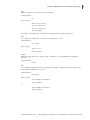
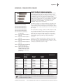
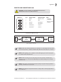
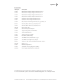
User I/O Connector Specifications
All Inputs are pulled high to +5 VDC through a 10k resistor
All Outputs are at TTL Logic Levels
Pin Assignments
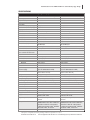
1.
Direction control input
Rising edge sets pump to infuse
Falling edge sets pump to refill
2.
Trigger Input
Event trigger – falling edge
triggers a program event
3.
Footswitch Input
Momentary switch closure to
ground or TTL Logic Low;
falling edge toggles between
states (run/stop)
4.
Trigger 1 Output
TTL Logic Output-Default = Low
Control thru method or serial
comm
5.
Trigger 2 Output
TTL Logic Output-Default = Low
Control thru method or serial
comm
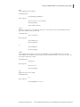
6.
Sync Output
TTL Logic Output –
Rising Edge = Start Infuse
Falling Edge= Start Refill
7.
Direction Output
TTL Logic Output –
High = Infuse
Low = Refill
8.
Valve Output
TTL Logic Output –
High = Valve Actuated
Low = Valve Off
Note: Valve follows direction
change when state is ‘auto’.
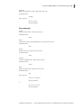
9-13. Signal Return / Ground
14. Run Indicator Voltage
+5V through a 470 ohm resistor
(connect to LED Anode)
15. Run Indicator Output
TTL Logic Output, active low
(low = run) (connect to LED
Cathode)
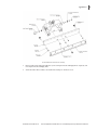
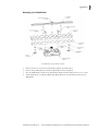
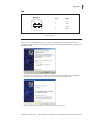
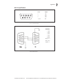
Trigger 1 Out
Trigger 2 Out
Footswitch In
Direction Out
Direction In
Sync Out
Event In
Valve Out
Run Indicator
Run Indicator or Voltage
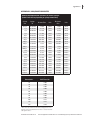
User I/O Connector Specifications
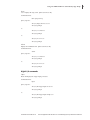
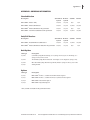
Electrical Specifications:
Inputs:
VIH ≥ 2V
VIL ≤ 0.4V
IIH ≤ 20µA
IIL ≤ 0.5mA
Outputs:
VOH ≥ 3.8V
VOL ≤ 0.4V
IOH ≤ 6mA
IOL ≤ 6mA
Publication 5419-006-Rev-A
Harvard Apparatus PHD ULTRA™ PC Controlled Syringe Pump Series User’s Manual
42