1
Conferencing and Discussion Systems
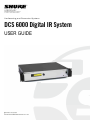
DCS 6000 Digital IR System
USER GUIDE
@2015 Shure Incorporated
User Manual DCS 6000 Digital IR System rev L.docx
DCS 6000 Digital IR System
User Manual
Table of Contents
Table of Contents .................................... 2
Testing during a meeting ......................16
Important ................................................ 4
Testing all positions ..............................16
Important Safeguards .......................... 4
Bad coverage ......................................16
Installation precautions ....................... 4
Black spots..........................................16
Cleaning ............................................... 4
Interference from IR systems ................17
Repacking ............................................. 4
DT 6008 & DT 6032 Transmitters........... 18
Warranty .............................................. 4
Description ......................................... 18
System description and planning............. 5
Installation ......................................... 19
System overview .................................. 5
Connections ........................................ 19
Infra-red transmitter ..............................5
Connecting the DCS 6000 Conference
System ...............................................19
Infra-red radiators .................................5
Infra-red receivers .................................5
System technology ............................... 5
IR radiation ...........................................5
Signal Processing ...................................6
Quality modes .......................................6
Carriers and channels .............................7
Aspects of IR distribution systems ....... 7
Receiver directional sensitivity.................7
Footprint of the radiator .........................7
Ambient lighting ....................................8
Objects, surfaces and reflections .............9
Positioning the radiators .........................9
Overlapping footprints and multipath effects
......................................................... 10
Planning an DCS 6000 Digital infra-red
radiation system ................................. 11
Rectangular footprints .......................... 11
Connecting other audio sources .............19
Connecting an emergency signal ............19
Connecting another transmitter .............20
Using the configuration menu ............. 21
Overview ............................................21
Navigate through the menu ...................21
Examples ............................................23
Configuration and operation ............... 26
Start-up ..............................................26
Main menu ..........................................26
View transmitter status .........................27
View fault status ..................................27
Set monitoring options .........................28
View version information .......................28
Set transmission mode .........................29
Set number of channels ........................29
Planning radiators ................................ 12
Set channel quality and assign inputs to
channels .............................................30
Cabling ............................................... 12
Set channel names ...............................31
Setting radiator delay switches .......... 12
Disable or enable carriers ......................31
System with one transmitter ................. 13
View carrier assignments ......................31
System with two or more transmitters in
one room ............................................ 15
Configure auxiliary inputs......................32
System with more than 4 carriers and a
radiator under a balcony ....................... 16
Enable / disable IR-monitoring...............33
Set sensitivity of the inputs ...................32
Testing the coverage area .................. 16
Enable/disable headphone output...........33
Testing during installation ..................... 16
Choose transmitter name ......................33
@2015 Shure Incorporated
User Manual DCS 6000 Digital IR System rev L.docx
DCS 6000 Digital IR System
User Manual
Reset all options to factory default values33
IR Transmitters Specification ............. 45
Digital Radiators.................................... 34
DT 6008/6032 Infrared Digital Transmitter
.........................................................45
Medium & High Power Radiators ........ 34
Description ......................................... 34
Radiator status indication ..................... 34
Mounting the radiators ......................... 35
Connecting radiators to the transmitter .. 37
Radiators & Accessories ...................... 46
RA 6013 / RA 6025 High Power Radiators46
WB 6000 Wall Mounting Bracket ............46
Receivers & Battery Packs .................. 47
Digital Receivers ................................... 38
DR 6004, DR 6008 & DR 6032 Digital IR
Receivers ............................................47
Description ......................................... 38
BP 6001 NiMH Battery Pack ...................47
Operation ........................................... 38
Charging Trays .................................... 47
Reception test mode ........................... 39
CT 6056 Charging Tray .........................47
Receiver headphones .......................... 39
Connection details .............................. 48
CT 6056 Charging Tray .......................... 40
Description ......................................... 40
Charging procedure ............................ 40
Troubleshooting .................................... 41
Typical schematics ................................ 43
Technical Specifications ........................ 44
Mains cables ........................................48
Audio cables ........................................48
Earphones ...........................................48
Emergency switch ................................48
Accessories ......................................... 49
Guaranteed footprints ......................... 50
System Specification .......................... 44
@2015 Shure Incorporated
User Manual DCS 6000 Digital IR System rev L.docx
DIS Digital Conference System
User Manual
Important
Important Safeguards
Cleaning
Prior to installing or operating this product
always read the Safety Instructions which are
available as a separate document.
To keep the cabinet in its original condition,
periodically clean it with a soft cloth. Stubborn
stains may be removed with a cloth lightly
dampened with a mild detergent solution. Never
use organic solvents such as thinners or abrasive
cleaners since these will damage the cabinet.
Installation precautions
Do not install the unit in a location near heat
sources such as radiators or air ducts, or in a place
exposed to direct sunlight, excessive dust or
humidity, mechanical vibration or shock.
Repacking
Save the original shipping cardboard box and
packing material; they will become handy if you
ever have to ship the unit. For maximum
protection, re-pack the unit as originally packed
from the factory.
To avoid moisture condensations do not install the
unit where the temperature may rise rapidly.
When the rechargeable battery pack is used, it is
advisable to check regularly after three years that
the batteries are not leaking. If there is any sign of
leakage or corrosion, replace the battery pack.
Ensure that only the battery pack BP 6001 is used.
The battery pack has to be replaced at least every
five years.
Warranty
The individual units in the DCS 6000 system are
minimum covered by 12 months warranty
against defects in materials or workmanship.
4
DIS Digital Conference System
User Manual
System description and planning
Both types can be switched between full and half
power use. They can be mounted on walls,
ceilings or floor stands.
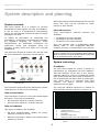
System overview
DCS 6000 Digital IR is a system for wireless
distribution of audio signals via infra-red radiation.
It can be used in a simultaneous interpretation
system for international conferences where multiple
languages are used.
Infra-red receivers
Three multi-channel
available:
•
•
•
To enable all participants to understand the
proceedings, interpreters simultaneously translate
the speaker’s language as required. These
interpretations are distributed throughout the
conference venue, and delegates select the
language of their choice and listen to it through
headphones.
infra-red
receivers
are
DR 6004 for 4 audio channels
DR 6008 for 8 audio channels
DR 6032 for 32 audio channels
They can operate with a rechargeable NiMH
battery pack or with disposable batteries.
Charging circuitry is incorporated in the receiver.
Note: The charging unit used for charging the
receivers fitted with a rechargeable NiMH battery
pack as well as the rechargeable battery pack will
not be available before year 2006.
The DCS 6000 Digital IR system can also be used
for music distribution (mono as well as stereo).
System technology
IR radiation
Figure 0-A
The DCS 6000 Digital IR system is based on
transmission by modulated infra-red radiation.
Infra-red radiation forms part of the electromagnetic spectrum, which is composed of visible
light, radio waves and other types of radiation. It
has a wavelength just above that of visible light.
Like visible light, it is reflected from hard
surfaces, yet passes through translucent
materials such as glass.
DCS 6000 Digital IR system overview (with DCS 6000system as input)
The DCS 6000 Digital IR Audio distribution System
comprises one or more of the following:
The infra-red radiation spectrum in relation to
other relevant spectra is shown in Figure 0-A.
%
100
Infra-red transmitter
The transmitter is the core of the DCS 6000 Digital
IR system. Two types are available:
•
•
75
1
50
DT 6008 with inputs for 8 audio channels
DT 6032 with inputs for 32 audio channels
25
Infra-red radiators
4
2
0
400
Two types of radiators are available:
•
RA 6013 medium-power radiator for small/
medium conference venues
•
RA 6025 high-power radiator for medium/large
conference venues
1
2
3
4
5
Figure 0-A
5
5
500
600
700
800
3
900
1000 nm
Daylight spectrum
Sensitivity of the human eye
IR radiator
Sensitivity of IR sensor
Sensitivity of IR sensor with daylight filter
Infra-red radiation spectrum in relation to other
spectra
DIS Digital Conference System
User Manual
Signal Processing
convert the carrier signals to modulated
infra-red light. In the IR receivers a reverse
processing is used to convert the modulated
infra-red light to separate analogue audio
channels.
The DCS 6000 Digital IR system uses high
frequency carrier signals (typically 2-8 MHz) to
prevent interference problems with modern light
sources (see section ‘IR radiation’). The digital
audio processing guarantees a constant high audio
quality. The signal processing in the transmitter
consists of the following main steps (see Figure
0-B):
In the IR receivers a reverse processing is used
to convert the modulated infra-red light to
separate analogue audio channels.
Quality modes
1. A/D conversion - Each analogue audio channel
is converted to a digital signal.
The DCS 6000 Digital IR system can transmit
audio in four different quality modes:
2. Compression - The digital signals are
compressed to increase the amount of
information that can be distributed on each
carrier. The compression factor is also related to
the required audio quality.
3. Protocol Creation - Groups of up to four digital
signals are combined into a digital information
stream. Extra fault algorithm information is
added. This information is used by the receivers
for fault detection and correction.
5. Radiation – Up to 8 modulated carrier signals
are combined and sent to the IR radiators, which
4x
Audio
Channel
Figure 0-B
Mono, conference quality, maximum 32
channels (standard quality)
•
Mono, Hi FI quality, maximum
channels (premium quality)
•
Stereo, conference quality, maximum 16
channels (standard quality)
•
Stereo, Hi FI quality, maximum
channels (premium quality)
16
8
The conference quality mode uses less
bandwidth and can be used for transmitting
speech. For music the HI-FI quality mode gives
near CD quality.
4. Modulation - A high frequency carrier signal is
phase-modulated with the digital information
stream.
Audio
Channel
•
A/D Conversion
& Compression
Protocol Creation
& Modulation
4x
A/D Conversion
& Compression
Overview of the signal processing (for one carrier)
6
Carrier (to IR Radiators)
DIS Digital Conference System
User Manual
Carriers and channels
The DCS 6000 Digital IR system can transmit up to
8 different carrier signals (depending on the
transmitter type). Each carrier can contain up to 4
different audio channels.
The maximum number of channels per carrier is
dependent on the selected quality modes. Stereo
signals use twice as much bandwidth as a mono
signal, premium quality uses twice as much
bandwidth as standard quality. Per carrier a mix of
channels with different quality modes is possible, as
long as the total available bandwidth is not
exceeded.
The table below lists
combinations per carrier:
all
possible
channel
Figure 0-C
Directional characteristics of the receivers
Channel Quality
Mono
Conference
Mono
Stereo
Stereo
Hi-Fi
Conference
Hi-Fi
4
2
Possible
number of
channels
4 x 10 kHz
1
2
1
per carrier
2 x 10 kHz and 1 x 20 kHz
1
2 x 10 kHz and 1 x 10 kHz (left) and 1 x 10 kHz (right)
1
1 x 20 kHz and 1 x 10 kHz (left) and 1 x 10 kHz (right)
2
2 x 10 kHz (left) and 2 x 10 kHz (right)
2
2 x 20 kHz
1
Figure 0-D
Bandwidth
1 x 20 kHz (left) and 1 x 20 kHz (right)
Possible channel combinations per carrier
Rotating the receiver will decrease the
sensitivity. For rotations of less than +/- 45
degrees this effect is not large, but for larger
rotations the sensitivity will decrease rapidly.
Aspects of IR distribution systems
A good infra-red distribution system ensures that all
delegates in a conference venue receive the
distributed signals without disturbance. This is
achieved by using enough radiators, placed at well
planned positions, so that the conference venue is
covered with uniform Irradiation of adequate
strength.
Footprint of the radiator
The coverage area of a radiator depends on the
number of transmitted carriers and the output
power of the radiator. The coverage area of the
RA 6025 radiator is twice as large as the
coverage area of the RA 6013. The coverage area
can also be doubled by mounting two radiators
side by side. The total radiation energy of a
radiator is distributed over the transmitted
carriers. When more carriers are used, the
coverage area gets proportionally smaller.
There are several aspects that influence the
uniformity and quality of the infra-red signal, which
must be considered when planning an infra-red
radiation distribution system. These are discussed
in the next sections.
Receiver directional sensitivity
The receiver requires a strength of the IR signal
of 4 mW/m2 per carrier to work without errors
(resulting in a 80 dB S/N ratio for the audio
channels). The effect of the number of carriers
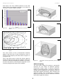
on the coverage area can be seen in Figure 0-A
The sensitivity of a receiver is at its best when it is
aimed directly towards a radiator. The axis of
maximum sensitivity is tilted upwards at an angle
of 45 degrees (see Figure 0-C).
7
DIS Digital Conference System
User Manual
and Figure 0-B. The radiation pattern is the area
within which the radiation intensity is at least the
minimum required signal strength.
Figure 0-A
Figure 0-C
The radiator mounted at 15° to the ceiling
Figure 0-D
The radiator mounted at 45° to the ceiling
Figure 0-E
The radiator mounted perpendicular (at 90°) to the
ceiling
Total coverage area of RA 6013 & RA 6025 for 1 to 8
carriers
1
2
4
8
Figure 0-B
Polar diagram of the radiation pattern for 1, 2, 4 & 8
carriers
The cross section of the 3-dimensional radiation
pattern with the floor of the conference venue is
known as the footprint (the white area in Figure 0-C
to Figure 0-E).
This is the floor area in which the direct signal is
strong enough to ensure proper reception, when the
receiver is directed towards the radiator. As shown,
the size and position of the footprint depends on the
mounting height and angle of the radiator.
Ambient lighting
The DCS 6000 Digital IR system is practically
immune for the effect of ambient lighting.
Fluorescent lamps (with or without electronic
ballast or dimming facility), such as TL lamps or
energy saving lamps give no problems with the
DCS 6000 Digital IR system. Also sunlight and
artificial lighting with incandescent or halogen
lamps up to 1000 lux give no problems with the
DCS 6000 Digital IR system.
8
DIS Digital Conference System
User Manual
When high levels of artificial lighting with
incandescent or halogen lamps, such as spotlights
or stage lighting are applied, you should directly
point a radiator at the receivers in order to ensure
reliable transmission. For venues containing large,
unscreened windows, you must plan on using
additional radiators.
For events taking place in the open air a site test
will be required in order to determine the required
amount of radiators. With sufficient radiators
installed, the receivers will work without errors,
even in bright sunlight.
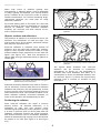
Figure 0-G
Infra-red signal blocked by a person in front of the
participant
Figure 0-H
Infra-red signal not blocked by a person in front of the
participant
Objects, surfaces and reflections
The presence of objects in a conference venue can
influence the distribution of infra-red light. The
texture and colour of the objects, walls and ceilings
also plays an important role.
Infra-red radiation is reflected from almost all
surfaces. As is the case with visible light, smooth,
bright or shiny surfaces reflect well. Dark or rough
surfaces absorb large proportions of the infra-red
signal (see Figure 0-F). With few exceptions it
cannot pass through materials that are opaque to
visible light.
100%
Figure 0-F
40%
100%
80%
The figures below illustrate how infra-red
radiation can be directed to conference
participants. In Figure 0-I, the participant is
situated clear from obstacles and walls, so a
combination of direct and diffused radiation can
be received. Figure 0-J shows the signal being
reflected from a number of surfaces to the
participant.
The texture of the material determines how much light is
reflected and how much is absorbed
Problems caused by shadows from walls or furniture
can be solved by ensuring that there are sufficient
radiators and that they are well positioned, so that
a strong enough infra-red field is produced over the
whole conference area. Care should be taken not to
direct radiators towards uncovered windows, as
most of this radiation will subsequently be lost.
Positioning the radiators
Since infra-red radiation can reach a receiver
directly and/or via diffused reflections, it is
important to take this into account when
considering the positioning of the radiators. Though
it is best if receivers pick up direct path infra-red
radiation, reflections improve the signal reception
and should therefore not be minimized. Radiators
should be positioned high enough not to be blocked
by people in the hall (see Figure 0-G and Figure
0-H).
Figure 0-I
9
Combination of direct and reflected radiation
DIS Digital Conference System
Figure 0-J
Combination of several reflected signals
User Manual
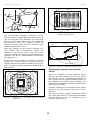
Figure 0-L
Radiator positioning in a conference hall with
auditorium seating and podium
Figure 0-M
Radiator for covering seats beneath a balcony
For concentrically arranged conference rooms,
centrally placed, angled radiators located high up
can cover the area very efficiently. In rooms with
few or no reflecting surfaces, such as a darkened
film-projection room, the audience should be
covered by direct path infra-red radiation from
radiators positioned in front.
When the direction of the receiver changes, e.g.
with varying seat arrangements, mount the
radiators in the corners of the room (see Figure
0-K). If the audience is always directed towards the
radiators, you do not need radiators at the back
(see Figure 0-L).
If the path of the infra-red signals is partially
blocked, e.g. under balconies, you should cover the
‘shaded’ area with an additional radiator (see Figure
0-M). The figures below illustrate the positioning of
the radiators:
Overlapping footprints and multipath
effects
When the footprints of two radiators partly
overlap, the total coverage area can be larger
than the sum of the two separate footprints. In
the overlap area the signal radiation power of
two radiators are added, which increases the
area where the radiation intensity is larger than
the required intensity.
However, differences in the delays of the signals
picked up by the receiver from two or more
radiators
Figure 0-K
Radiator position for covering seats in a square
arrangement
can result in that the signals cancel each other
out (multi path effect). In worst-case situations
this can lead to a loss of reception at such
positions (black spots).
10
DIS Digital Conference System
User Manual
beyond the horizontal point
rectangular footprint starts.
at
which
the
The guaranteed rectangular footprints for
various number of carriers, mounting heights
and mounting angles can be found in section 0.
The height is the distance from the reception
plane and not from the floor.
Figure 0-N
Increased coverage area caused by added radiation
power
H
W
X
L
Figure 0-A
Figure 0-O
Reduced coverage area caused by differences in cable
signal delay
H
Figure 0-N and Figure 0-O illustrate the effect of
overlapping footprints and differences in signal
delays. The lower the carrier frequency, the less
susceptible the receiver is for differences in signal
delays. The signal delays can be compensated by
using the delay compensation switches on the
radiators (see section 0).
W
X
L
Figure 0-B
Planning an DCS 6000 Digital infra-red
radiation system
Rectangular footprints
Determining the optimal number of infra-red
radiators required to give 100% coverage of a hall
can normally only be done by performing a site test.
However, a good estimation can be made by using
‘guaranteed rectangular footprints’.
Figure 0-A and Figure 0-B show what is meant by a
rectangular footprint. As can be seen, the
rectangular footprint is smaller than the total
footprint. Note that in Figure 0-B the ‘offset’ X is
negative because the radiator is actually mounted
A typical rectangular footprint for a mounting angle of
15°
A typical rectangular footprint for a mounting angle of
90°
Guaranteed rectangular footprints can also be
calculated with the footprint calculation tool
(available on the documentation CD-ROM). The
given values are for one radiator only, and
therefore do not take into consideration the
beneficial effects of overlapping footprints. The
beneficial effects of reflections are also not
included. As rule of thumb can be given for
systems with up to 4 carriers, that if the receiver
can pick up the signal of two adjacent radiators
the distance between these radiators can be
increased by a factor 1.4 approximately (see
Figure 0-C).
11
DIS Digital Conference System
User Manual
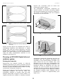
R1
R2
R3
R4
R2
50m
W
1.4 W
R1
50m
R3
R4
50m
L
1.4 L
Figure 0-C
The effect of overlapping footprints
50m
Planning radiators
Use the following procedure to plan the radiators:
Figure 0-D
Radiators with equal cable length
Figure 0-E
Asymmetrical arrangement of radiator cabling (to be
avoided)
Figure 0-F
Symmetrical arrangement
(recommended)
1. Follow the recommendations in section 0 in
order to determine the positioning of the
radiators.
2. Look up (in the table) or calculate (with the
Footprint
Calculation
Program
DIS_FCPv5.3_.xlt) the applicable rectangular
footprints.
3. Draw the rectangular footprints in the lay-out of
the room.
4. If the receiver can pick up the signal of two
adjacent radiators in some areas, determine the
overlap effect and draw the footprint
enlargement(s) in the lay-out of the room.
5. Check whether you have sufficient coverage
with the radiators at the intended positions.
6. If not so, add additional radiators to the room.
See Figure 0-K, Figure 0-L and Figure 0-M for
examples of a radiator lay out.
Tip:
The
Footprint
Calculation
Program
DIS_FCPv5.3_.xlt eases the work planning radiator
coverage. The Program is to be found at the ‘DCS
6000 Digital IR System User Manual CD’
Cabling
Signal delay differences can occur due to
differences in the cable length from the transmitter
to each radiator. In order to minimize the risk of
black spots, use equal cable length from transmitter
to radiator if possible (see Figure 0-D). When
radiators are loop-through connected, the cabling
between each radiator and the transmitter should
be as symmetrical as possible (see Figure 0-E and
Figure 0-F). The differences in cable signal delays
can be compensated with the signal delay
compensation switches on the radiators.
of
radiator
cabling
Setting radiator delay switches
As described in section 0, differences in the
delays of the signals picked up by the receiver
from two or more radiators can cause black spots
as a result of the multi path effect. The signals
picked up by the receiver are delayed by:
the transmission from transmitter to radiator
through the cable (cable signal delay)
the transmission from radiator to receiver
through the air (radiation signal delay)
12
DIS Digital Conference System
for systems with two or more transmitters: the
transmission through the slave transmitter(s)
To compensate the signal delay differences, the
delay of each radiator can be increased. These
signal delays can be set with the delay switches at
the back of the radiator.
The cable signal delays can be determined in the
following two ways:
by measuring the cable lengths
by measuring the impulse response time with a
delay measurement tool
In both cases the cable signal delays can be
calculated manually and with the delay switch
calculation tool (available on the documentation
CD-ROM). It is not necessary to calculate the cable
signal delay in case:
the radiators are directly connected to the
transmitter with equal cable length;
radiators are loop-through connected, but with
less than 5 m distance between the first and last
radiator in a trunk, and with equal cable length
between the first radiator in each trunk and the
transmitter.
User Manual
3. Multiply the lengths of the cables between the
transmitter and each radiator with the cable
signal delay per meter. These are the cable
signal delays for each radiator.
4. Determine the maximum signal delay.
5. Calculate for each radiator the signal delay
difference with the maximum signal delay.
6. Divide the signal delay difference by 33. The
rounded off figure is the signal delay switch
position for that radiator.
7. Add delay switch positions for radiators under
a balcony, if applicable (see section 0).
8. Set the delay switches to the calculated
switch positions.
Note: For systems with a cable length difference
of more than 50 meters, it is recommended to
use a measurement tool to determine the delay
differences in order to calculate the delay switch
positions.
Figure 0-A and Table 0-1 illustrate the calculation
of the cable signal delay.
In these cases set the delay switches on all
radiators to zero and determine whether to
compensate for radiation signal delay (see section
0).
Note: The used cable signal delay per meter is
an example. Use the actual signal delay per
meter in this calculation as specified by the
manufacturer.
The next sections describe how to calculate the
delay switch positions manually for systems with
one transmitter, or two or more transmitters. See
the delay switch calculation tool for the procedures
how to calculate the delay switch positions
automatically.
Caution: Turn the delay switches carefully to a
new position until you feel that it clicks into
position, to prevent that a switch is positioned
between two numbers, which would result in a
wrong delay setting.
Tip:
The
Delay
Switch
Calculation
tool
DIS_DSCv5.3a_.XLT eases the calculation of the
delay switch positions. The Program is to be found
at the ‘DCS 6000 Digital IR System User Manual
CD’.
20m
30m
R1
R2
System with one transmitter
20m
Determining delay switch positions by
measuring the cable lengths
R3
Use the following procedure to determine the delay
switch position based on cable lengths:
30m
1. Look up the cable signal delay per meter of the
used cable. The manufacturer specifies this
factor.
2. Measure the lengths of the cables between the
transmitter and each radiator.
R5
R4
20m
Figure 0-A
13
System with five radiators and measured cable
lengths
DIS Digital Conference System
Radiator
number
User Manual
Total cable
length [m]
Cable signal
delay per meter
[ns/m]
Cable signal delay
[ns]
Signal delay
difference [ns]
1
30
5,6
30*5.6 = 168
280-168 = 112
2
30+20 = 50
5,6
50*5.6 = 280
280-280 = 0
Delay switch position
112/33 = 3.39 = 3
0/33 = 0
3
20
5,6
20*5.6 = 112
280-112 = 168
168/33 = 5.09 = 5
4
30
5,6
30*5.6 = 168
280-168 = 112
112/33 = 3.39 = 3
5
30+20 = 50
5,6
50*5.6 = 280
280-280 = 0
Table 0-1
0/33 = 0
Calculation of the cable signal delays
Determining delay switch positions by using a
delay measuring tool
Set the delay switches to the calculated delay
switch positions.
The most accurate way to determine the cable
signal delays is to measure the actual signal delay
for each radiator as described in the following
procedure:
Figure 0-B and Table 0-2 illustrate the calculation
of the signal delays and the delay switch
positions.
1. Disconnect the cable from a radiator output of
the transmitter and connect this to a delay
measurement tool.
2. Disconnect a radiator from this cable.
3. Measure the impulse response time (in ns) of
the cable(s) between the transmitter and the
radiator.
4. Reconnect the cable to the radiator and repeat
steps 2 to 4 for the other radiators that are
connected to the same transmitter output.
Note The calculated delay switch positions based
on impulse response time can differ from the
calculated delay switch positions based on cable
lengths. This is caused by the accuracy of the
measurements and the accuracy of the cable
signal delay factor per meter as specified by the
manufacturer of the cable. If the impulse
response time is measured correctly, the
calculated delay switch positions will be the most
accurate.
584 ns
350 ns
R2
R1
5. Reconnect the cable to the transmitter and
repeat step 1 to 5 for the other radiator outputs
of the transmitter.
6. Divide the impulse response times for each
radiator by two. These are the cable signal
delays for each radiator.
237 ns
R3
7. Determine the maximum signal delay.
8. Calculate for each radiator the signal delay
difference with the maximum signal delay.
9. Divide the signal delay difference by 33. The
rounded off figure is the delay switch position
for that radiator.
R5
R4
563 ns
339 ns
Figure 0-B
Calculation System with five radiators and measured
impulse response times
10. Add delay switch positions to radiators under a
balcony, if applicable (see section 0)
Radiator
number
Impulse response
time [ns]
Cable signal delay
[ns]
1
350
350/2 = 175
2
584
584/2 = 292
292-292 = 0
0/33 = 0
3
237
237/2 = 118
292-118 = 174
174/33 = 5.27 = 5
4
339
339/2 = 169
292-169 = 123
123/33 = 3.73 = 4
5
563
573/2 = 281
292-281 = 11
11/33 = 0.33 = 0
Table 0-2
Signal delay
difference [ns]
292-175 = 117
Calculation of the delay switch positions of a system with one transmitter
14
Delay switch position
117/33 = 3.54 = 4
DIS Digital Conference System
User Manual
8. Add delay switch positions to radiators under
a balcony, if applicable (see section 0)
System with two or more transmitters in one
room
9. Set the delay switches to the calculated delay
switch positions
When radiators in one multi-purpose room are
connected to two transmitters, an extra signal delay
is added by:
Figure 0-C, Table 0-1, Table 0-3 and Table 0-4
illustrate the calculation of the extra masterslave signal delay.
Transmission from master transmitter to slave
transmitter (cable signal delay).
50m
Transmission through the slave transmitter.
R1
Use the following procedure to determine the delay
switch positions in a master-slave configuration:
1. Calculate the cable signal delay for each
radiator, using the procedures for a system with
one transmitter.
50m
R2
Tx1
50m
2. Calculate the signal delay of the cable between
the master and the slave transmitter in the
same way as for cables between a transmitter
and a radiator.
R3
R4
50m
3. Add to the cable signal delay of the cable
between the master and the slave, the delay of
the slave transmitter itself: 33 ns. This gives the
master-to slave signal delay.
50m
Tx2
R5
50m
4. Add the master-to-slave signal delay to each
radiator connected to the slave transmitter.
5. Determine the maximum signal delay.
R6
6. Calculate for each radiator the signal delay
difference with the maximum signal delay.
50m
Figure 0-C
7. Divide the signal delay difference by 33. The
rounded off figure is the signal delay switch
position for that radiator.
System with master and slave transmitter in multi
purpose room
Cable length masterslave transmitter [m]
Cable signal delay
per meter [ns/m]
Cable signal
delay [ns]
Signal delay
slave transmitter
[ns]
50
5,6
50 x 5.6 = 280
33
Table 0-3
Master-to-slave signal delay
[ns]
280 + 33 = 313
Calculation of the master-to-slave signal delays
Radiator
number
Transmitter
Master-toslave
signal
Cable signal
delay per
meter [ns/m]
Cable signal
delay [ns]
Signal delay
difference
[ns]
1
Master
0
168
0+168 = 168
593-168 = 425
425/33 = 12.88 = 13
2
Master
0
280
0+280 = 280
593-280 = 313
313/33 = 9.48 = 9
3
Master
0
112
0+112 = 112
593-112 = 481
481/33 = 14.58 = 15
4
Master
0
168
0+168 = 168
593-168 = 425
425/33 = 12.88 = 13
5
Master
0
280
0+280 = 280
593-280 = 313
313/33 = 9.48 = 9
6
Slave
313
168
313+168 = 481
593-481 = 112
112/33 = 3.39 = 3
7
Slave
313
280
313+280 = 593
593-593 = 0
8
Slave
313
112
313+112 = 425
593-425 = 168
168/33 = 5.09 = 5
9
Slave
313
168
313+168 = 481
593-481 = 112
112/33 = 3.39 = 3
10
Slave
313
280
313+280 = 593
593-593 = 0
Table 0-4
Calculation of the delay switch positions of a system with two transmitters
15
Delay switch position
0/33 = 0
0/33 = 0
DIS Digital Conference System
User Manual
Note: When a master-slave configuration is used for rooms which are always separated, the delay switch
positions can be determined per system and the delay caused by transmission from master to slave
transmitter can be ignored.
Caution: Turn the delay switches carefully to a new position until you feel that it clicks into position, to
prevent that a switch is positioned between two numbers, which would result in a wrong delay setting.
System with more than 4 carriers and a
radiator under a balcony
Figure 0-D illustrates a situation in which a radiation
signal delay occurs and which can be compensated
for. For systems with more than four carriers, add
one delay switch position per 10 meter (33 feet)
difference in signal path length to the radiators
which are closest to the overlapping coverage area.
In Figure 0-D the signal path length difference is 12
meter. Add one delay switch position to the
calculated switch position(s) for the radiator(s)
under the balcony.
16m
4m
Testing during a meeting
1. Set a receiver in the Test-mode and select
the highest available carrier. The quality of
the received carrier signal is indicated on the
display of the receiver (see section 0).
2. Test all positions and directions (see next
paragraph). The quality indication should be
between 00 and 39 (good reception).
Testing all positions
With the transmitter and receiver in one of the
two test modes, go around the conference hall
and test the reception quality at every position
where the infra-red signals must be received.
When an area is detected where there is bad
reception or even no reception at all, three main
causes must be considered:
Bad coverage
Figure 0-D
Radiation path length difference for two radiators
Testing the coverage area
An extensive reception quality test must be done to
make sure that the whole area is covered with IR
radiation of adequate strength and that there are
no black spots. Such a test can be done in two
ways:
Testing during installation
1.
Check that all radiators are connected and
powered up and that no loose cables are
connected to a radiator. Switch the transmitter
off and on to re-initialize the auto equalization
of the radiators.
2. Set the transmitter in the Test-mode (see
section 0). For each channel, a different test
tone frequency will be transmitted.
3. Set a receiver on the highest available channel
and listen via the headphones to the transmitted
test tone.
4. Test all positions and directions (see next
paragraph).
The receiver cannot pick-up infra-red radiation of
adequate strength. This can be because the
tested position is outside the footprint of the
installed radiators or the radiation is blocked by
obstacles such as a column, an overhanging
balcony or other large objects.
Check that you used the correct footprints for the
system design, that radiators with enough output
power are installed and that a radiator is not
accidentally switched to half power operation.
When the bad reception is caused by a blocked
radiation path, try to remove the blocking
obstacle or add an extra radiator to cover the
shaded area.
Black spots
The receiver picks-up IR signals from two
radiators which cancel out each other. The
multipath effect can be identified by the
observation that the bad reception only occurs
along a specific line and/or when good reception
returns when the receiver is rotated to another
direction.
This can be confirmed by keeping the receiver in
the position and direction with the bad reception
and then either shading-off the radiation from
16
DIS Digital Conference System
one radiator with your hand or switching off one
radiator. If this improves the reception quality, then
the multipath effect is causing the problem. Note
that IR radiation that is reflected from a surface with
a high reflectabiliy can also cause multipath
problems.
Black spots can occur in case a transmitter is
located in the same room as the radiators. In that
case, disable the mini IR radiator of the transmitter
with the configuration menu (see section 2.5.16).
Check that the signal delay compensation switches
on the radiators are set to the correct value and that
a switch is not accidentally positioned between two
numbers. Re-check your system design. When
User Manual
necessary, reduce the distance between the two
radiators that cause the problem and/or add an
extra radiator. Note that due to the physical
characteristics of the signal distribution, it is not
always possible to completely avoid multi path
effects.
Interference from IR systems
IR assistive hearing systems and IR microphones
operating at frequencies above 2 MHz can disturb
the reception at the lowest carriers. If such is the
case, disable the lowest two carriers (see section
0) and re-check the reception.
17
DIS Digital Conference System
User Manual
DT 6008 & DT 6032 Transmitters
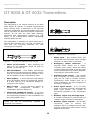
Description
The transmitter is the central element of the DCS
6000 Digital IR system. It accepts asymmetrical
audio sources from a maximum of 32 external
channels (dependent on the transmitter type) and
can be used with the DCS 6000 Digital Conference
System. It can also be used with analogue
discussion and interpretation systems (e.g. CIE
9000), or as a stand-alone system distributing
external audio sources.
Figure 0-B
Back view of DT 6008 Transmitter
Figure 0-C
Back view of DT 6032 Transmitter
The transmitter is suitable for either table-top or
19-inch rack-mounted use. Four feet (for table top
use) and two mounting brackets (for rack
mounting) are supplied.
Figure 0-A
1. Mains input – Euro mains socket. The
transmitter has automatic mains voltage
selection. A mains cable is provided.
Front view of DT 6008 and DT 6032 Transmitter
2. Emergency switch connector – A
terminal block socket for a single,
‘normally open’ switch. When the switch
is closed, the audio signal on the Aux right
input is distributed on all output channels,
overriding all other audio inputs.
1. Mains on/off switch – After switching the
mains on, the transmitter starts up and the
display (3) will light-up.
2. Mini IR-radiator – Four IREDs, transmitting
the same infra-red signal as the radiator output.
This can be used for monitoring purposes. They
can be disabled via the configuration menu.
3. Auxiliary audio inputs – Two female
XLR connectors for extra audio inputs.
They can be used to connect auxiliary
symmetrical audio signals such as a
music installation, the floor language or
emergency messages.
3. Menu display – A 2x16 character LCD-display
gives information about the transmitter status.
It is also used as a an interactive display for
configuring the system.
4. Menu button – A turn-and-push button to
operate
the
configuration
software
in
combination with the display (3).
4. Audio signal inputs – 8 or 32 cinch
plugs to connect external asymmetrical
audio input signals. The number of
connectors depends on the transmitter
type.
5. Monitoring headphone output – A 3.5 mm
(0.14 inch) jack socket to connect a headphone
for monitoring purposes. It can be disabled via
the configuration menu.
5. Radiator signal loop-through input –
A HF BNC connector to loop-through the
radiator output of another transmitter.
Note: The mini IR-radiator and the headphone
output can also be permanently disabled by
removing two resistors
6. Radiator signal outputs – Six HF BNC
connectors,
used
to
connect
the
radiators. Up to 30 radiators can be loopthrough connected to each output. RG59
Cable must be used.
18
DIS Digital Conference System
Installation
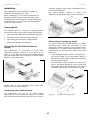
The transmitter can be placed on a table or
installed in a standard 19” rack.
User Manual
congress systems from other manufacturers or
for music distribution.
The audio signals (stereo or mono) are
connected to the audio input cinch connectors.
When installing in a 19” rack the supplied 19”
brackets shall be fixed to the front side of the
transmitter by unscrewing the crews holding the
top and button cover and then fix the brackets
using the same screws.
Connections
This chapter gives an overview of typical system
connections using the DT 60xx range transmitter:
Connecting the DCS 6000 Conference System
Connecting other external audio sources
Connecting an emergency signal switch
Connecting another transmitter
Connecting the DCS 6000 Conference
System
The transmitter is connected to DCS 6000
Conference System directly to a CU 6105 or CU
6110 or to an AO 6004 or AO 6008 Audio Output
Unit. Each AO 6008 can feed up to 8 ‘Audio Signal
Inputs’ in the transmitter.
Figure 0-B
Connecting external audio sources to the transmitter
Connecting an emergency signal
To use the emergency signal function, a switch
(normally-open) must be connected to the
emergency switch connector. The reaction of the
transmitter on a closed switch depends on the
configuration of the auxiliary inputs (see also
section 0):
If the auxiliary input is 'Mono + Emergency',
the audio signal on the Aux-Right input is
distributed to all output channels, overriding
all other audio inputs.
If the auxiliary input is 'Stereo' or 'Stereo to
Mono', the audio signals on the Aux-Left and
Aux-Right inputs are distributed to all output
channels, overriding all other audio inputs.
Figure 0-A
Connecting the DCS 6000 Conference System.
Please refer to the individual DCS 6000 user
manuals for more information.
Connecting other audio sources
The transmitter has up to 32 audio inputs
(depending on the transmitter type) to interface
with external asymmetrical audio sources, such as
Figure 0-C
19
Connecting an emergency signal
DIS Digital Conference System
User Manual
Connecting another transmitter
The transmitter can be operated in slave mode to
loop through the IR radiator signals from a master
transmitter.
One of the six radiator outputs of the master
transmitter is connected with an RG59 cable to the
radiator signal loop-through input of the slave
transmitter.
The Transmission mode of the slave transmitter
must be set to ‘Slave’ (see section 0).
Figure 0-D
20
Connecting another transmitter
DIS Digital Conference System
User Manual
Using the configuration menu
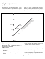
Overview
All configuration and operation options of the
transmitter are set via an interactive menu, using a
2x16 character LCD display and a ‘turn-and-push’
menu button.
Figure 0-A gives an overview of the menu
structure. A general description of how to use the
menu is given in section 0. Some examples are
given in section 0. The detailed descriptions of all
menu items can be found in section 0.
.
Transmitter
Status
0
4P Defaults
Fault Status
1
4O Unit Name
4N Headphone on/off
4M Mini Radiator on/off
4L Level Inputs
4K
3D FW Version
Monitoring
4J
2
3C FPGA Version
4I
4H
3B HW Version
Level Aux. Right
Level Aux. Left
Aux. Input Mode
Carrier Overview
4G Carrier Settings
3A Serial Number
Enquiry
4F
4E
3
Channel Names
Language List
4D Channel Quality
4C
4B
4A
Setup
Network Mode
Transmission Mode
4
<
Figure 0-A
Number of Channels
Back
Menu overview
Cycle through the available values for a
settable option (the value is blinking).
Navigate through the menu
Operating the menu is always a sequence of
alternating turns and pushes:
Push the button to:
Confirm a chosen menu item (the menu item
number and title stops blinking, a blinking
cursor appears).
Turn the button to:
Cycle through the menu items within a menu
(the menu item number and title on the first line
is blinking).
Go to a sub-menu (the sub-menu item
character starts blinking).
Go to a settable option within a menu item (a
blinking cursor moves through the menu
screen).
Confirm the selection of a settable option (the
cursor disappears, the option value starts
blinking).
21
DIS Digital Conference System
User Manual
Confirm a selected value for a settable option
(the value stops blinking, the cursor appears
again).
Note: To enter the Setup sub-menu, push and
hold the button for at least 3 seconds.
After 3 minutes of inactivity, the display
automatically switches back to the first item of the
Main menu (Transmitter Status).
1. Turn the button to move the cursor to the
submenu item character.
Each menu item is identified by a number (for the
Main menu) or by a number plus a character (for
the sub-menus). The item identification can be
found at the start of the first line and is used to
navigate to and from sub-menus.
Most menu items have one or more settable
configuration options. The value of an option can be
changed by selecting a value from a list of available
values.
To navigate through a sub-menu:
2. Push the button. The item character and title
starts blinking.
3. Turn to select
character.
another
sub-menu
item
4. Push to confirm the selection.
To change option values:
1. Navigate to the applicable menu item.
To navigate through the Main menu:
2. Turn the button to move the cursor to the
option value you want to change.
Turn the button to move through the Main menu
items. The item number and title starts blinking.
(The first item, Transmitter Status, doesn’t blink.)
3. Push the button to activate the option. The
option value starts to blink.
To jump to a sub-menu:
1. Navigate in the Main menu to an item with three
dots (e.g. ‘Setup ...’).
2. Push the button to go to the sub menu. The
submenu item character and title starts
blinking.
main menu
item number
sub-menu
item character
4C
Ch.
Quality
Per
Channel
...
Figure 0-B
4. Turn the button to select a new option value.
5. Push the button to confirm the new value.
The option value stops blinking.
6. Turn the button to move the cursor to
another settable option (when available) and
repeat steps 3 to 5.
menu item title
three dots indicate
that the item has a
sub-menu
4C
Channel
Stereo
PQ
12
In
03
option values
Menu item screen elements
To jump back from a sub-menu to an item of
the Main menu:
1. Turn the button to move the cursor to the Main
menu item number.
2. Push the button. The item number and title
starts blinking.
3. Turn to select another item number.
4. Push to confirm the selection.
When you are turning counter-clockwise through
submenu items, the display jumps automatically
to the Main menu after you have reached the first
item (A) of the sub-menu. Example:
To jump back from an item of the Main menu
to the Transmitter Status:
1. Turn the button to the < Back screen.
2. Push the button to go to the Transmitter
Status.
22
DIS Digital Conference System
User Manual
Examples
Each step in the examples below shows the text on
the display and the action to go to the next step.
Bold text in italics (text) indicates that the text is
blinking. An underscore ( _ ) indicates the position
4 C Nr. of Ch.
32 Channels
4 A Transmission
On
of the cursor. Each example starts at the
Transmitter Status screen.
4 Setup
3 Enquiry
...
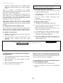
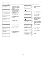
Example 1: Disable carrier 2. (See also section ‘Disable or enable carriers‘)
Transmitter
32 Channels
1
Turn the button to
select the ‘Setup’
item (4) in the Main
menu.
4 Setup
2
Push and hold the
button for 3 sec. to
go to the ‘Setup’
submenu.
Turn to select the
‘C.Settings’ submenu item (4G).
4 A
Transmission
On
3
4 G
C.Settings...
4
4G Carrier 0
Enabled
4G Carrier 2
Enabled
4G Carrier 2
Enabled
5
6
7
Push to go to the
‘C.Settings’ submenu.
Turn
to
carrier 2.
select
4G Carrier 2
Enabled
8
Push to confirm.
4G Carrier 2
Enabled
9
Turn to select
‘Disabled’.
4G Carrier 2
Disabled
1
0
Push to confirm
4G Carrier 2
Disabled
1
1
4G Carrier 2
Disabled
1
2
Turn to move the
cursor to the Main
menu item number
(4).
Push to confirm.
4 Setup ...
1
3
Turn to select the
< Back screen
< Back ...
1
4
Push to confirm
Transmitter
32 Channels
1
5
Ready
Push to confirm.
Turn to move the
cursor
to the second line.
23
DIS Digital Conference System
User Manual
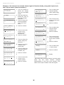
Example 2: Assign a user defined name to ch. 12. (See also section ‘Disable or enable carriers‘)
Transmitter
32 Channels
1
Turn the button to
select the ‘Setup’
item (4) in the Main
menu.
4 Setup
2
Push and hold the
button for 3 sec. to
go to the ‘Setup’
submenu.
Turn to select the
‘C.Settings’ submenu item (4G).
4 A Transmission
On
4F Ch.Names ...
Floor
4F Channel 00
Spanish
3
4
5
Push to go to the
‘Ch. Names’ submenu.
Turn to select the
required channel
number (12).
4F Channel 12
• - - -
1
1
Turn to move the
cursor to the first
dash.
4F Channel 12
o - - -
1
2
Push to confirm.
4F Channel 12
o - - -
1
3
Turn to select the
first character (C).
4F Channel 12
o C--
1
4
Push to confirm
this character.
4F Channel 12
o C--
1
5
Repeat steps 11 to
14 for the other
characters.
4F Channel 12
o CD Music
1
6
Turn to move the
cursor to the Main
menu item number
(4).
4F Channel 12
Spanish
6
Push to confirm.
4F Channel 12
Spanish
7
Turn to move the
cursor to the start
of the second line.
4F Channel 12
o CD Music
1
7
Push to confirm.
4G Carrier 12
Spanish
8
Push to confirm.
4 Setup ...
1
8
Turn to select the
< Back screen
4F Channel 12
Spanish
9
Turn clockwise
until channel name
changes to: • - - -
< Back ...
1
9
Push to confirm
4F Channel 12
• - - -
1
0
Push to confirm.
Transmitter
32 Channels
2
0
Ready
24
DIS Digital Conference System
User Manual
Example 3: Set channel 11 to transmit a Stereo signal in Premium Quality, using audio inputs 14 (L)
and 15 (R) as source. (See also section 0.)
Transmitter
32 Channels
1
4 Setup
2
Turn the button to
select the ‘Setup’
item (4) in the Main
menu.
1
3
Turn to select the
required quality
value (Stereo PQ).
1
4
Push to confirm. *
Stereo PQ In 12
1
5
Turn to move the
cursor to the input
number.
4D Channel 11
Stereo PQ In 12
1
6
Push to confirm.
4D Channel 11
1
7
Turn to select the
required input
number (14).
1
8
Push to confirm.
1
9
Turn to move the
cursor to the Main
menu item number
(4).
Push to confirm.
4D Channel 11
Mono SQ In 10
4D Channel 11
4 A Transmission
On
3
4D Ch. Quality
All Mono SQ
4
4D Ch. Quality
All Mono SQ
5
Push and hold the
button for 3 sec. to
go to the ‘Setup’
submenu.
Turn to select the
Channel Quality’
sub-menu item
(4D).
Stereo PQ In 10
4D Channel 11
Push to confirm.
Stereo PQ In 12
4D Ch. Quality
6
Turn to move the
cursor to the
option on the
second line.
Push to confirm.
4D Channel 11
Stereo PQ In 14
4D Channel 11
All Mono SQ
Stereo PQ In 14
4D Ch. Quality
7
All Mono SQ
Turn to select the
option value ‘Per
Channel ...’.
4D Channel 11
Stereo PQ In 14
4D Ch. Quality
Per Channel ...
4D Channel 00
8
9
Mono SQ In 00
4D Channel 11
Mono SQ In 00
4D Channel 11
Mono SQ In 10
4D Channel 11
Mono SQ In 10
Push to go to the
‘Channel’ submenu (4C).
Turn to select the
required channel
number (11).
1
0
Push to confirm.
1
1
Turn to move the
cursor to the
quality option.
1
2
Push to confirm.
2
0
4 Setup ...
2
1
Turn to select the
< back screen
< Back ...
2
2
Push to confirm
Transmitter
32 Channels
2
3
Ready
* Note that after selecting ‘Stereo’ as input mode
(step
14)
the
input
number
changes
automatically to the next even number (12),
which is the input number of the left signal.
25
DIS Digital Conference System
User Manual
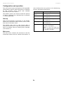
Configuration and operation
The next sections give descriptions of the possible
configuration options. Each description is followed
by the relevant menu items with detailed
information per menu option.
also contains the entry points to the Monitoring,
Enquiry and Setup sub-menus.
Menu Item
Item Description
Transmitter
Status
Shows the transmitter
(see section 0)
1 Fault Status
Shows the radiator fault status
(see section 0)
Start-up
2 Monitoring . . .
When the transmitter is switched on, the display
shows the Transmitter Status screen, which is the
first item of the Main menu.
Go to the ‘Monitoring’ sub-menu
(see section 0)
3 Enquiry . . .
Go to the ‘Enquiry’ sub-menu
(see section 0)
4 Setup . . .
Go to the ‘Setup’ sub-menu (see
sections 0 and higher)
The default values (see section ‘Reset all options
to factory defaults’) are indicated by an asterisk
(*) when applicable.
The display also goes to this screen after 3
minutes of inactivity. In case the system detects a
fault, the display shows a flashing fault message
(see section 0).
status
Note: To enter the Setup submenu, push and hold the button
for at least 3 seconds
Main menu
The main menu contains the screens to view the
transmitter status and the radiator fault status. It
26
DIS Digital Conference System
User Manual
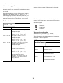
View transmitter status
1 Fault Status
The first screen of the Main menu gives
information about the present status of the
transmitter. The screen shows the name of the
transmitter (1st line) and the present transmission
mode (2nd line). (See section 0 to change the
transmission mode).
1 Fault Status
No Faults
Options
Description
No Faults
The connected radiators function
without problems.
Radiator Fault
One of the connected radiators is
not functioning properly.
No Radiators
No radiators are connected to
the transmitter.
Transmitter Status
DT 6008
10 Channels
Options
Description
Name
The first line shows the name of the
transmitter (see section 0 for
changing).
Modes
The second line shows the actual
transmission mode:
nn channels
Audio signals are distributed on nn
channels.
Aux to All
The signal on the Aux. inputs is
distributed on all channels.
nn Ch. Test
The test signals are distributed on nn
channels.
Slave
The transmitter operates in slavemode: the radiator signal on the slave
input is looped-through to all radiator
outputs
Standby
The transmitter is in standby mode
(not transmitting).
Emergency Call
An emergency signal from the Aux.
inputs is distributed to all channels.
View fault status
The fault status of the radiators can be seen in the
second screen of the Main menu:
.
When the system detects a failure for the first
time, a flashing fault message pops-up on any
menu screen:
Radiator Fault
or
No Radiators
or
No Network
or
Network Error
Push the menu button to remove the fault
message from the screen and to go back to the
menu screen that was visible before the fault
message popped-up. The flashing message will
also disappear when the fault has been resolved.
27
DIS Digital Conference System
User Manual
Set monitoring options
The Monitoring sub-menu (2) is used to set which
signal is sent to the monitoring headphone output.
It can be one of the inputs, one of the channels or
no signal.
When the sensitivity of one of the inputs is being
changed in the Setup menu (4I, 4J or 4K), or
when assigning inputs to channels (menu 4C, Per
Channel), the monitoring output automatically
switches temporarily to that source, even when
the option ‘None’ has been chosen.
2 Monitoring
When the headphone output is disabled (see
section 0), the output level cannot be changed
and the level indicator is not visible.
The ‘Source/volume’ screen also displays level
meters (two for a stereo source, one for a mono
source) for a visual indication of the actual
signal strength:
2 Monitoring
In. 04
-9 dB
= low level
Options
Description
= high level
In. nn dd dB
The signal from audio input “nn” is
available on the monitoring
headphone output
= overflow.
Input nr. “nn”:
Volume: “dd” dB
Ch. nn dd dB
{00 ... 31}
{-31 ... 0}
The signal on channel “nn” is
available on the monitoring
headphone output.
View version information
In the Enquiry sub-menu (3), version
information of the transmitter can be found.
This information should be mentioned in service
requests or failure reports.
Channel nr. “nn”: {00 ... 31}
Volume: “dd” dB {-31 ... 0}
Aux.L
dd dB
3 Enquiry
The signal on the Aux. Left input is
available on the monitoring
headphone output.
3A Serial Number
FC.0.0012D
Volume: “dd” dB {-31 ... 0}
AuxR
dd dB
The signal on the Aux. Right input is
available on the monitoring
headphone output.
Volume: “dd” dB {-31 ... 0}
None
dd dB
Options
Description
3A Serial
Number
Shows the serial number of the
transmitter board.
3B HW Version
The monitoring headphone output is
switched off during normal
operation, but is active when the
sensitivity of one of the inputs is
being changed.
Shows the version number of
the transmitter board.
3C FPGA
Version
Shows the version number of
the FPGA software of the
transmitter board.
Volume: “dd” dB {-31 ... 0}
3D FW Version
Shows the version number of
the transmitter firmware.
28
DIS Digital Conference System
Set transmission mode
The Transmission Mode menu item (4A) is used
to select which signals will be distributed over the
channels. It is also possible to switch all channels
off (Standby).
4 Setup/4A Transmission
4A Transmission
ON
Options
Standby
On
Aux to All
User Manual
Set number of channels
Via sub-menu item 4B the number of channels
that will be used can be set.
Note that the maximum number of channels
depends on the transmitter type (8 or 32
channels) and the chosen quality modes.
4 Setup/4B Nr. of Ch.
4A Nr. of Ch.
Manual: 08
Description
All channels are switched off, no
signals are distributed.
Normal transmission. Input
signals are distributed on the
channels as set in the Channel
Quality sub-menu (4D).
Options
Description
Automatic: nn
The number of used channels is
set automatically to the
maximum possible number of
channels depending on
transmitter type and the
selected quality modes).
The signals on the Auxiliary
inputs are distributed on one
carrier to all channels.
Test
A different test tone is
distributed on each channel.
The frequency increases with
increasing channel number. For
stereo channels the tone for left
and right will also be different.
Slave
The radiator signal on the slave
input is looped-through to all
radiators.
Channels “nn”:
Manual:
nn
{1 ... 32}
Set the number of used
channels (the maximum
number depends on the
transmitter type and the
selected quality modes).
Channels “nn”:
{1 ... 32}
An asterisk (*) is shown when the selected
number is not possible because it is higher than
the maximum number of channels.
29
DIS Digital Conference System
User Manual
Set channel quality and assign inputs to
channels
Channel nr. “nn”: {00 ... 31}
Disabled
The audio quality of the channels (mono/stereo,
standard/premium) can be set in sub-menu 4D.
The quality can be set the same for all channels or
for each channel separately. Note that choosing
stereo and/or premium quality uses more
bandwidth and decreases the number of available
channels (see section 0). In stereo mode, the left
signal is always an even numbered input. The next
higher input number is used for the right signal.
When the quality is set the same for all channels
with the ‘All Mono’ or ‘All Stereo’ options, the
inputs are assigned automatically to the channels
as indicated in the table below:
All Mono
In nn
Input nr. “nn”:
Mono SQ
In nn
Input
Channel
Input L
Input R
00
00
00
00
01
01
01
01
02
03
...
...
...
...
...
31
31
15
30
31
Mono PQ
In nn
Set selected channel to mono,
premium quality.
Input nr. “nn”:
31}
Stereo SQ In nn
Set selected channel to stereo,
standard quality.
Input nr. “nn”:
31}
Stereo PQ In nn
Set selected channel to stereo,
premium quality.
Input nr. “nn”:
31}
Set all channels to mono, standard
quality.
All Mono PQ
Set all channels to mono, premium
quality.
All Stereo
SQ
Set all channels to stereo, standard
quality.
All Stereo
PQ
Set all channels to stereo, premium
quality.
Per Channel
...
Select this option to go to the ‘Per
Channel Settings’ menu.
Note: An asterisk (*) is shown behind the
channel number when the channel in the
configured quality does not fit on the available
carriers (see section 0).
4 Setup/4C Ch. Quality
4C Channel 01
Mono SQ In 01
Description
4C Channel nn
Select which channel to
configure.
{00 ...
Select the audio input that
should be distributed on the
selected channel. For stereo
signals, the input number of the
left signal (even number)
should be selected.
Per Channel Settings
Options
{00 ...
Select the audio input that
should be distributed on the
selected channel. For stereo
signals, the input number of the
left signal (even number)
should be selected.
4C Ch. Quality
All Mono SQ
All Mono SQ
{00 ...
Select the audio input that
should be distributed on the
selected channel.
4 Setup/4C Ch. Quality
Description
{00 ...
Select the audio input that
should be distributed on the
selected channel.
With menu option 4C (Per Channel Settings), the
assignment can also be done for each channel
separately.
Options
{00 ... 31}
Set selected channel to mono,
standard quality.
Input nr. “nn”:
31}
All Stereo
Channel
Disable selected channel.
30
DIS Digital Conference System
User Manual
Set channel names
4 Setup/4F C. Settings
Each channel can be assigned a name via the
Channel Names menu (4E). This can be ‘Floor’ or
one of 30 pre-defined ISO language names. Also
up to 32 user-defined names can be added.
4F Carrier 0
Enabled
The language in which the pre-defined names are
presented can be chosen via the Language List
menu option (4D).
Options
Description
4F Carrier n
Select which carrier to configure.
Carrier nr. “n”:
4 Setup/4D Language List
4D Language List
English
{0 ... 8}
Disabled
The selected carrier is disabled
(off).
Enabled
The selected carrier is enabled
(on).
Options
Description
English
Present language list in English.
View carrier assignments
French
Present language list in French.
Original
Present each language name in
it’s original language (e.g.
English, Français, Deutsch,
etc.).
With menu option 4H the carrier assignment
can be seen, i.e. which channels are
transmitted on each carrier.
Note that the number of channels that can be
distributed on one carrier depends on the
chosen quality mode.
4 Setup/4E Ch. Names
4 Setup/4G C. Overview
4E Channel 01
English
4G Carrier 0
Ch. 00 01 02 03
Options
Description
Options
Description
4E Channel nn
Select which channel to name.
4H Carrier n
Select which carrier to view.
Channel nr. “nn”: {00 ... 31}
‘Floor’
Use this name for the channel
that carries the ‘Floor’
language.
ISO language
names
Choose from pre-programmed
ISO language names.
User defined
names
Up to 32 userdefined names
(max. 12 characters) can be
added and chosen.
Carrier nr. “n”:
Ch nn nn nn nn
{0 ... 8}
Shows the channel numbers that
are assigned to the selected
carrier. The symbol ‘- -’ is used
when less than 4 channels are
assigned.
Channel nr. “nn”: {00 ... 31}
If the channel number is
represented one time Mono SQ
is assigned to this carrier.
If the channel number is
represented two times Mono PQ
or Stereo SQ is assigned to this
carrier.
Disable or enable carriers
Normally the channels are automatically assigned
to the available carriers. However, when the
reception quality of a specific carrier is not good,
that carrier can be disabled manually. The
channels are then automatically re-assigned to the
next available carriers.
If the channel number is
represented four times Stereo
PQ is assigned to this carrier.
Each of the 8 carriers (0 to 7) can be disabled or
enabled in the Carrier Settings menu (4F).
31
DIS Digital Conference System
User Manual
Configure auxiliary inputs
Options
Description
The way the signals on the auxiliary inputs (Aux-.L
and Aux.-R) are handled can be set in the Aux.
Input Mode menu (4H).
xx db
Set the required sensitivity for
the left auxiliary input.
Level “xx” dB:
When the option ‘Stereo’ is chosen, the signals on
both Aux. inputs are distributed as a stereo signal
to all channels. This setting can for instance be
used to transmit a music signal during breaks in a
conference.
4 Setup/4J Level Aux. R
4J Level Aux.R
0 dB
Note that the Transmission mode must be set to
‘Aux to All’ (menu item 4A) to actually transmit
this stereo signal.
The ‘Stereo to Mono’ and ‘Mono+ Emergency’
options can be selected when the transmitter is
used in combination with an interpretation system.
The
Aux.
inputs
will
be
distributed in stereo to all
channels when the transmission
mode (menu item 1) is set to
‘Aux to All’.
Stereo to Mono
Mono +
Emergency
The Aux-L and Aux-R inputs are
combined into a mono signal and
distributed to the Symmetrical
Audio Input.
Set the required sensitivity for
the right auxiliary input.
{-6 ... +6}
Options
Description
All
Set the sensitivity of all audio
inputs to a user defined level.
xxdB
Level “xx” dB:
Per Input ...
{-6 ... +6}
Select this option to go to the
‘Per Input Sensitivity Settings’
menu.
Per Input Sensitivity settings
4 Setup/4K Level Inputs
The Aux-L input is distributed to
the Symmetrical Audio Input
and
4K Sens. Input 00
0 dB
Interpreters
Module
(when
present). The Aux-R input is
distributed as emergency signal
to all channels when the
emergency switch is closed.
Set sensitivity of the inputs
Options
Description
4K Sens.Input
nn
Select which input to set.
xx db...
Select the required sensitivity.
Input nr. “nn”:
Level “xx” dB:
+6}
The sensitivity of the audio and Aux. inputs can be
set in the Input Sensitivity menus (4I, 4J, 4K).
The sensitivity can be set the same for all audio
inputs (menu item 4K) or for each audio input
separately.
xx db
4K Level Inputs
All
-6 dB
4H Aux. Input
Stereo
Stereo
Description
4 Setup/4K Level Inputs
4 Setup/4H Aux. Input
Description
Options
Level “xx” dB:
The Aux. input(s) will be distributed to the
Symmetrical Audio Input.
Options
{-6 ... +6}
{00 ... 31}
{-6 ...
The sensitivity screens also display a level
meter for a visual indication of the actual signal
strength:
4 Setup/4I Level Aux. L
= low level
= high level
4I Level Aux.L
0 dB
= overflow.
32
DIS Digital Conference System
User Manual
Enable / disable IR-monitoring
4 Setup/4N Unit Name
The mini IR-radiator at the front of the transmitter
can be used for monitoring the IR-signal.
4M Headphone
DT 6008
When required (e.g. for security reasons) this
option can be switched off (menu 4L).
4 Setup/4L Mini Radiator
Options
Description
Free Text
Assign a user defined name to
the transmitter (max. 16
characters). The default name
is ‘DT 6008’ or ‘DT 6032’
depending of the model.
4L Mini Radiator
Enabled
Options
Description
Enabled
Disabled
Enable or disable the mini IRradiator at the front of the
transmitter.
Enable/disable headphone output
The headphone output at the front of the
transmitter can be used for monitoring the inputand channel signals.
Reset all options to factory default values
Use menu item 4O to reset all options to the
factory defaults. The user defined transmitters
name, the user defined language names and
the transmission mode are not reset. (The
default values are indicated by an asterisk (*)
in the menu descriptions.)
4 Setup/4O Defaults
When required (e.g. for security reasons) this
option can be switched off in menu item 4M.
4O Reset to
defaults? No
4 Setup/4M Headphone
4m Headphone
Enabled
Options
Description
Enabled
Disabled
Enable or disable the
headphone output at the front
of the transmitter.
Options
Description
No
Cancel Reset.
Yes
Reset all options to the factory
default value.
The user defined transmitters
name, the user defined
language names and the
transmission mode are not
reset.
Choose transmitter name
The transmitter can be assigned a user-defined
name. This name is used in the Transmitter Status
screen. The name can be edited in the Unit Name
menu (4N).
33
DIS Digital Conference System
User Manual
Digital Radiators
Medium & High Power Radiators
Description
These units accept the carrier signals generated by
the transmitter and emit infra-red radiation
carrying up to 32 audio distribution channels. They
are connected to one or more of the six HF BNC
outputs of the IR transmitter.
A maximum of 30 radiators can be connected to
each of these outputs by means of loop through
connections. The RA 6013 has an infra-red output
of 16 Wpp, while the RA 6025 has an infra-red
output of 32 Wpp. Both have an automatic mains
power voltage selection and are switched on
automatically when the transmitter is switched on.
The attenuation of the signal by the cable is
equalized automatically by the radiator.
When the radiator is supplied with power and the
transmitter is switched on, the radiator initializes
the equalization. The red LEDs flash for a brief
period of time to indicate that the initialization is in
progress. When not receiving carrier waves, the
radiators switch to standby mode.
There is also a temperature protection mode which
automatically switches the radiators from full to
half power or from half power to stand-by if the
temperature of the IREDs becomes too high.
5 6
Figure 0-B
5 6
RA 6013 and RA 6025 front view
1. Mains input - Male Euro mains connector.
The radiators have automatic mains voltage
selection.
2. IR signal input/loop-through - Two HF
BNC connectors for connecting the radiator to
the transmitter and for loop-through
connection to other radiators. Automatic
cable termination is achieved by a built-in
switch in the BNC connectors. RG59 Cable
must be used.
3. Output power selection switch - The
radiators can be switched between full- and
half-power operation.
4. Delay compensation switches - Two 10position
switches
to
compensate
for
differences in cable lengths to the radiators.
1
100-240 V
Loop - Through inputs
Do not
terminate
2
Output power
3
High
Low
Delay compensation
X10
4
5. Amber indicator LEDs - Give an indication
of the radiator status.
6. Red indicator LEDs - Give an indication of
the radiator status.
Note: The indicator LEDs are positioned behind
the semi-transparent cover and are only visible
when ON.
X1
Radiator status indication
Figure 0-A
RA 6013 and RA 6025 back view
A radiator consists of two IRED panels. Each
IRED panel has an amber and a red indicator
LED (see Figure 0-B) which show the status of
the radiator panel
34
DIS Digital Conference System
User Manual
Red LED
Amber LED
Status
on
off
Stand-by mode
off
on
Transmitting
flashing
on
At switch-on:
Initializing signal
equalization
Warning: When you install the radiator in a
ceiling, you must leave at least 1 m3 of free
space around the back of the radiator. To
prevent the radiator from becoming too hot,
make sure that there is a good airflow in this
free space.
During operation:
Temperature protection
mode.
See chapter 6,
Trouble-shooting
on
If IRED panel failure:
See chapter 6,
Trouble-shooting
Mounting the radiators
Radiators in permanent installations can be either
fixed to a wall, hung under a ceiling or balcony or
secured to any sturdy material, using the
suspension bracket supplied with the radiator. The
mounting angle can be adjusted for optimal
coverage.
For wall mounting a separate bracket is also
required. In non-permanent installations, a floor
stand can be used.
Figure 0-C
Attaching the plate to the suspension bracket
Figure 0-D
Attaching the suspension bracket to the radiator
Attaching the suspension bracket
First assemble the supplied suspension bracket
and connect it to the radiator (see Figure 0-C and
Figure 0-D).
This bracket is attached to the radiator by two
bolts with washers. There are corresponding holes
on the back of the radiators. There is also a
spring-loaded plunger (indicated by a black arrow
in Figure 0-D), located above the bolt hole on the
right-hand arm of the bracket, which is used for
adjusting the angle of the radiator (shown in inset
in Figure 0-D). There are corresponding holes on
the back of the radiator for accepting this plunger.
The mounting angle can be adjusted in steps of
15°.
Warning: Always ensure that natural airflow is
not obstructed by ceilings, walls etc. when
determining the position of the radiator. Leave
plenty of space around the radiator to prevent it
becoming too hot.
Note: When in operation, the radiators may feel
warm to the touch. This is quite normal, and does
not indicate a radiator fault or malfunction.
Mounting on a floor stand
The top of the floor stand is screwed into the
suspension bracket (Figure 0-E). The bracket is
supplied with both metric and Whitworth
threaded plates, and is therefore compatible
with most standard floor stands.
For floor stands, the mounting angle can be set
at 0°, 15° or 30°.
35
DIS Digital Conference System
User Manual
diameter and 60 mm in depth must be drilled
using the drilling pattern (see Figure 0-G).
Note: The four bolts used to attach the bracket
must each be able to withstand a pull-out force
of 200 kg (440 lb).
The bolts and plugs delivered with the WB 6000
wall bracket are only intended for mounting the
unit on a solid brick or concrete wall.
For attaching the bracket to a drywall Fisher
plug HM 6x37 S K in combination with a 6 mm
washer must be used ensuring that the
mounting bracket is successfully mounted to a
wall.
Figure 0-E
Attaching the stud of a floor stand to the suspension
bracket of the radiator
Figure 0-G
WB 6000 wall mounting bracket showing dimensions
and drilling pattern
The radiator (plus suspension bracket) is
attached to the wall bracket by sliding the
mounting bolt over the slot on the wall bracket
and then tightening it (see Figure 0-I). A split
pin is then inserted into a small hole in the bolt
to stop it from working loose (see inset in
Figure 0-I). The vertical angle of the radiator
can be adjusted between 0 and 90° in steps of
15°. The horizontal orientation of the radiator
can be adjusted by loosening the bolt then
turning the radiator to the required position.
Figure 0-F
Attaching the radiator inclusive suspension bracket and
stud to the FS floor stand
Wall mounting
For wall mounting, the WB 6000 wall bracket is
required (must be ordered separately).
This bracket is attached to the wall by means of
four bolts (see Figure 0-H). Four holes of 10 mm in
36
DIS Digital Conference System
User Manual
Ceiling mounting
The radiators can be attached to the ceiling
using the supplied suspension bracket. This
ensures enough space for a proper air flow
around the radiator. Mounting a radiator in the
ceiling will in most cases require a forced air
flow by means of a ventilator to prevent
overheating.
Mounting on horizontal surfaces
When the radiator has to be positioned a
horizontal surface (e.g. on top of an interpreter
booth), the distance between the radiator and
the surface must be at least 4 cm (1.5 inch) to
enable enough air flow around the radiator.
This can be achieved by using the suspension
bracket as a support. If this is not possible,
switch the radiator to half power. If the radiator
is used at full power on top of an interpreter
booth, the ambient temperature must not
exceed 35° C.
Figure 0-H
Attaching the wall mounting bracket to a wall
Connecting radiators to the transmitter
The transmitter has six BNC HF Output
connectors labeled 1, 2, 3, 4, 5 and 6 on the
rear panel. All six outputs are functionally
identical. They can each drive up to 30 radiators
(RA 6013 and/or RA 6025) in a loop-through
configuration. The radiators are connected with
RG59 cables. The maximum cable length per
output is 900 m (2970 ft) to the last radiator.
Automatic cable termination is achieved by a
built-in switch in the BNC connectors on the
radiator.
Notes: For the automatic cable termination to
work, never leave an open-ended cable
connected to the last radiator in a loop-through
chain.
When connecting infra-red radiators, do not
split the cable, else the system will not function
correctly.
Figure 0-I
Attaching the radiator to the wall mounting bracket
37
DIS Digital Conference System
User Manual
Digital Receivers
Description
The receivers are available for 4, 8 or 32 channels.
They can operate with a rechargeable NiMH
battery pack or with disposable batteries and have
controls for channel selection, volume adjustment
and an on/off push button. All receivers have a 3.5
mm (0.14 inch) stereo jack output socket for
mono or stereo headphones.
An LCD display shows the channel number and
indicators for signal reception and low battery
power.
Charging circuitry is included in the receiver.
5. Channel selector - An up/down switch to
select an audio channel. The channel number
is shown on the LCD display.
6. On/Off button - When a headphone is
connected, the receiver switches to Stand-by
state. Pressing the On/Off button switches
the receiver from Stand-by to On. To switch
back to Stand-by, press and hold the button
for approx. 2 seconds. When the headphone
is
removed,
the
receiver
switches
automatically to the Off-state.
7. Battery pack connector - This connection
is used to connect the battery pack to the
receiver. Charging is automatically disabled
when this connector is not used.
8. Charging contacts - Used in combination
with the charging equipment to recharge the
battery pack (if used).
9. Battery pack or disposable batteries Either a rechargeable BP 6001 NiMH battery
pack or two disposable AA-size 1.5 V
batteries.
Note: When the receiver is not used,
disconnect the headphones. This ensures that
the receiver is totally switched-of and no energy
is consumed from the batteries or the battery
pack.
Operation
Figure 0-A
Receiver, front view and back view
The receiver cannot operate when no
headphone is connected. After connecting the
headphone the receiver switches to stand-by
mode. Push shortly on the on/off button to
switch the receiver on.
1. Charging indicator LED - Used in combination
with the charging equipment.
The channel number is shown on the LCD
display.
2. Headphone connector - A 3.5 mm (0.14 inch)
stereo jack output socket for the headphone,
with integrated Stand-by/Off-switch.
The channel can be changed with the channel
selector.
3. LCD Display - A two digit display showing the
selected channel. An antenna symbol is visible
when the receiver picks up an infra-red signal of
adequate quality. A battery symbol is visible
when the battery pack or the batteries are
almost empty.
4. Volume control - A slider to adjust the volume.
Push it to the up- or down-position to increase
or decrease the channel number. The highest
channel number is automatically matched to the
number of channels that has been set on the
transmitter (see section 0).
A battery symbol is visible on the display when
the batteries or the battery pack is almost
empty.
38
DIS Digital Conference System
User Manual
An antenna symbol is visible when the receiver
picks up a modulated infrared signal of adequate
quality. During short interruptions in the reception,
the receiver mutes the headphones output. When
no adequate IR signal is detected for more than 1
minute (e.g. when a delegate leaves the
conference room), the receiver automatically
switches to stand-by mode.
Reception test mode
The volume can be changed by moving the volume
control up or down.
When in test-mode, switch between carriers by
using the channel selector. The receiver’s
display will shortly show the carrier number (07) and then a quality indication (00-90).
The receiver can be manually switched to stand-by
mode by pressing the on/off button for more than
2 seconds.
When the headphone is disconnected, the receiver
is automatically switched off. (A switch in the
headphone connector disconnects the batteries.)
The infra-red receivers can operate with disposable
batteries (2x AA-size alkaline cells) or with a
rechargeable battery pack (not available yet).
The receivers can be switched to a test-mode to
get an indication of the reception quality for
each carrier separately. To activate the testmode: Push the channel selector to the Upposition, press the on/off button and hold both
for ca. 2 seconds.
Note: When the receiver does not receive the
selected carrier, it keeps displaying the carrier
number and does not display its quality.
The reception quality can be assessed as
follows:
Insert the batteries or the battery pack in the
receiver with the correct polarity as indicated in
the battery compartment. The battery pack has a
separate connection cable which must be
connected to the receiver.
When this connection is not present, the charging
circuitry in the receiver will not work. This also
prevents the unwanted charging of disposable
batteries. The battery pack has a temperature
sensor which prevents overheating during
charging.
Note: Disposable batteries and battery packs at
the end of their technical lives should be discarded
with due care for the environment. When possible,
take batteries to a local recycling station.
Indication
Quality
00-39
Good reception. Very good audio
quality.
40-49
Weak reception. Ticks in the audio.
50-90
No or bad reception. Poor audio
quality.
The test mode is deactivated when the receiver
is switched off.
Receiver headphones
The headphones connect with the receivers via
a 3.5 mm (0.14 inch) stereo jack connector.
Suitable headphone types are:
DH 6021 Stereo headphones
(recommended)
Any other compatible type
39
DIS Digital Conference System
User Manual
CT 6056 Charging Tray
Description
LED color
Charging status
The charging tray can recharge up to 56 receivers
at once. The charging unit which is designed in a
suitcase for portable unit contains the power supply
with automatic mains voltage selection.
Green
Charging completed.
Red
Charging in progress.
Red blinking
Error status. See chapter 6,
The charging electronics and a charging indicator
LED are included in each receiver. The charging
circuitry checks if a battery pack is present and
controls the charging process.
Note: The charging tray is only intended to charge
DR 60xx receivers with a BP 6001 battery pack.
You cannot charge other receiver types with the
CT 6056 charging tray, nor can you use other
charging trays to charge DR 60xx receivers.
Trouble shooting
Off
Charger switched off or
receiver
not
properly
inserted.
Notes
• It is preferred to switch on the charging unit
before inserting the receivers. Receivers can be
inserted or removed without damage while the
charging unit is switched on.
• Charge the battery pack to full capacity before
using them for the first time.
• The charger always applies fast charge during
the first 10 minutes after inserting a receiver.
Inserting the receiver multiple times with a fully
charged battery pack should therefore be
avoided, as this will damage the battery pack.
Figure 0-A
Charging Tray, front view.
1. Main Input -Male Euro mains socket. The
charging unit has automatic mains voltage
selection.
A mains cable is provided.
2. Mains on/off switch
3. Receiver positions - One charging unit can
charge up to 56 receivers simultaneously
Charging procedure
Ensure that the charging tray is connected to the
mains and that it is switched on. Place the receivers
firmly in the charging compartments. The charging
indicator LEDs on all receivers should illuminate.
These LEDs indicate the charging status of each
receiver:
• Continuously charging the receiver will not
damage the receiver or battery pack. Receivers
can therefore safely be left in their charging
positions when they are not used.
Notes continued:
• When the rechargeable battery pack is used, it
is advisable to check regularly after three years
that the batteries are not leaking.
If there is any sign of leakage or corrosion,
replace the battery pack. Ensure that only the
battery pack BP 6001 is used.
The battery pack has to be replaced at least
every five years
40
DIS Digital Conference System
User Manual
Troubleshooting
In this chapter a simple fault-finding guide is
given.
This is intended to be used to remedy the
consequences of incorrect installation. If more
serious faults or problems arise the installer
should contact a qualified technician.
Transmitter display does not
light up:
Check that the mains supply to the transmitter is connected and
that the transmitter is switched on.
Transmitter indicates “no
radiators”:
Ensure that connections to all radiators have been made
correctly and that each radiator’s mains supply is connected and
switched on.
Transmitter indicates “radiator
fault”:
Ensure that connections to all radiators have been made
correctly and that each radiator’s mains supply is connected and
switched on.
Examine the radiator LEDs.
Emergency contact does not
work:
Check that the emergency contact is connected correctly.
Red LED flashes and amber LED
is on of one or both IRED panels
of a radiator:
IRED panel is in temperature protection mode. Check that the
natural airflow around that radiator is not obstructed. If not so,
replace the radiator.
Both red LED and amber LED are
on of one or both IRED panels of
a radiator:
IRED panel malfunctions and the radiator should be replaced.
Infra-red receiver fails to
function properly:
If disposable batteries are used, check whether the batteries
have sufficient capacity and whether they are inserted with the
correct polarity.
Check that the audio is connected according to the selected
auxiliary input mode (menu 4H).
If a battery pack is used, ensure that the battery pack is fully
charged.
Ensure that the headphone is connected properly.
Switch the receiver on and check whether the display indicates
a channel.
Ensure that the receiver picks up sufficient IR signal and check
whether the antenna symbol becomes visible.
Enable the mini radiator (menu 4L) and check the receiver by
holding it in front of the mini radiator of the transmitter.
Ensure that the volume control is turned up.
Set the transmitter in test mode and check whether the test
tone is audible on the receiver.
If the test tone is not audible, do the same test with other
receivers. If all receivers do not work properly at that spot, check
the coverage of the system (see section 0).
41
DIS Digital Conference System
The charging indicator LED on
the receiver is blinking:
User Manual
Check that the charging unit is used under the specified working
conditions (see technical data).
Check that the receiver contains a battery pack which is
connected correctly.
Ensure that the receiver is at room temperature and re-insert
the receiver in the charging unit.
If the charging indicator starts blinking again, replace the
battery pack and check whether the problem is resolved.
Receiver discharges very quickly:
Replace the battery pack and check whether the problem is
resolved.
Bad coverage:
Do the tests as described in section 0.
42
DIS Digital Conference System
User Manual
Typical schematics
The following schematic is showing a typical application with various units in the DCS 6000 system:
43
DIS Digital Conference System
User Manual
Technical Specifications
System Specification
Overall system characteristics
System Environmental Conditions
Conforms to IEC 60914, the international standard
for conference systems
Working condition
Conforms to IEC 61603 part 7, the international
standard for digital infra-red transmission of audio
signals for conference and similar applications
Temperature range
Transmission Characteristics
- transport
-40 to +70 °C (-40 to 158 °F)
- operating
+5 to +45 °C (41 to 113 °F)
+5 to +55 °C (41 to 131 °F)
for DT 6008 & DT 6032
IR transmission wavelength .......................... 870 nm
Modulation frequency
Carriers 0 to 5: 2 to 6 Hz,
according to IEC 61603 part
7,
Carriers 6 and 7: up to 8 MHz
Protocol and modulation DQPSK, according to
technique 61603 part 7
IEC
+5 to +35 °C (41 to 122 °F)
for BP 6001
Maximum relative humidity ...............................
........................ < 93%
Safety
System Audio Performance
(Measured from the audio input of a transmitter to the
headphone output of a receiver.)
EMC emission
According
to
harmonized
standard EN 55103-1 and FCC
rules part 15, complying with the
limits for a class A digital devices
EMC immunity
According
to
harmonized
standard EN 55103-2
EMC approvals
Affixed with the CE mark
ESD
According
to
harmonized
standard EN 55103-2
Mains harmonics
According
to
harmonized
standard EN 55103-1
....... 20 Hz to 20 kHz (-3 dB)
............... (Premium Quality)
Total harmonic distortion at 1 kHz ............... < 0.05%
Crosstalk
attenuation
at
1
kHz
.........................................
..............................> 80 dB
Dynamic range
..............................> 80 dB
Weighted
signal-to-noise
ratio
.........................................
......................... > 80 dB(A)
Cabling and System Limits
Cable type
Maximum
Environmental requirements ....................................
Contains no banned substances
as specified in UAT-0480/100
(e.g. no cadmium or asbestos)
..................... 75 Ohm RG59
number
of
radiators
.........................................
................. 30 per HF output
Maximum cable length
900 m (2,970 feet) per HF
output.
According
to
EN
60065,
CAN/CSA-E65 (Canada and US)
and UL 6500
According
to
EN
60065,
CAN/CSA-E65 (Canada and US)
and UL 1419 for RA 6013 & RA
6025
Audio frequency response ...... 20 Hz to 10 kHz (-3 dB)
.............. (Standard Quality)
............ Fixed, stationary or
transportable
Specifications are subject to change without
notice.
44
DIS Digital Conference System
User Manual
IR Transmitters Specification
DT 6008/6032 Infrared Digital Transmitter
Physical Characteristics
Mounting
Brackets
mounting
Symmetrical audio inputs ................ +15 dBV nominal
+ 18 dBV. Maximal (+/- 6 dB)
Emergency switch connector . emergency control input
for
19”
rack
Headphone output
..............32 Ohm to 2 kOhm
Detachable feet for freestanding use on a table top
HF input
Nominal 1 Vpp, minimum 10
mVpp, 75 Ohm
425 (483) x 87 x 317 (357)
mm (dimensions in brackets
are incl. the 19" mounting
brackets)
HF output
.........1 Vpp, 6 VDC, 75 Ohm
Mains voltage
.... 100 to 240 V, 50 to 60 Hz
Weight
...................... 4 kg (8.0 lbs)
Power consumption (standby) ........................... 29 W
Finish
...........Black with silver front
Dimensions
Electrical Characteristics
Asymmetrical audio inputs ................ +3 dBV nominal
Power consumption maximal ............................ 55 W
Specifications are subject to change without
notice.
. + 6 dBV Maximal (+/- 6 dB)
45
DIS Digital Conference System
User Manual
Radiators & Accessories
RA 6013 / RA 6025 High Power Radiators
Electrical and Optical Characteristics
Number of IREDs
Physical Characteristics
Mounting
(RA
Mounting plates for floor
stands with M10 and 1/2”
Whitworth thread
Total optical peak intensity............. 12 W/sr (RA 6013)
WB 6000 Wall Mounting
Bracket can be used for fixing
radiator to wall surfaces
Angle of half intensity
.............................. +/- 22°
HF input nominal
....... 1Vpp, minimal 10 mVpp
Mains voltage
...... 90 to 260 V, 50 to 60 Hz
Power consumption
............... 100 W (RA 6013),
RA 6025 without bracket:
300 x 500 x 175mm (11.0 x
19.7 x 6.9 in)
.............. 24 W/sr (RA 6025)
................ 180 W (RA 6025)
Power consumption (standby) ............. 8 W (RA 6013),
.................. 10 W (RA 6025)
Max. operation temperature
0, 15 and 30° for floor-stand
mounting
45 degrees ambient, normal
airflow
0, 15, 30, 45, 60, 75 and 90°
for wall/ceiling mounting.
Temperature protection will
activate when the radiator is
used
above
maximum
operating conditions.
RA 6013 without bracket:
.................... 6.8 kg (15 lbs)
RA 6013 with bracket:
WB 6000 Wall Mounting Bracket
.................... 7.6 kg (17 lbs)
Physical characteristics:
RA 6025 without bracket:
Dimensions (H x W x D)
.................... 9.5 kg (21 lbs)
Color
480
Total IR output at 20 °C 11 Wrms 22 Wpp (RA 6013),
21 Wrms 42 Wpp (RA 6025)
200 x 500 x 175mm (7.9 x
19.7 x 6.9 in)
Weight
6013),
Suspension bracket for direct
ceiling mounting
Dimensions (H x W x D) RA 6013 without bracket:
Radiator angle
260 (RA
6025)
........... 200 x 280 x 160 mm
............ (7.9 x 11.0 x 6.3 in)
RA 6025 with bracket:
Weight
.................... 1.8 kg (4.0 lb)
.................. 10.3 kg (23 lbs)
Finish
........................ Quartz grey
........... Finish Bronze colored
Specifications are subject to change without
notice.
46
DIS Digital Conference System
User Manual
Receivers & Battery Packs
DR 6004, DR 6008 & DR 6032 Digital IR
Receivers
Physical Characteristics
Dimensions (H x W x D) ............... 155 x 45 x 30 mm
.............. (6.1 x 1.8 x 1.2 in)
Supply voltage
.. 1.8 to 3.6 V, nominal 2.4 V
(battery voltage)
Power consumption at 2.4 V ............ 15 mA (speech at
maximum volume, 32 Ohm
headphone)
Power consumption (standby) ....................... < 1 mA
Weight excl. batteries/battery pack ...... 75 g (0.16 lb)
BP 6001 NiMH Battery Pack
Weight incl. battery pack ...................... 125 g (27 lb)
Physical characteristics
Finish
Dimensions (H x W x D)
..............Charcoal with silver
Electrical and Optical Characteristics
................ 14 x 28 x 49 mm
.............. (0.6 x 1.1 x 1.9 in)
IR irradiance level
........... 4 mW/m2 per carrier
Weight
Angle of half sensitivity
............................... +/-50°
Electrical characteristics
Headphone output level at 2.4V ............... 450 mVrms
(speech at max. volume, 32
Ohm headphone)
Voltage
................................. 2.4 V
Capacity
.......................... 1100 mAh
Specified lifetime:
...... Minimum 2 years or 500
cycles (under normal
conditions)
Headphone output freq. range .......... 20 Hz to 20 kHz
Headphone output impedance ....... 32 Ohm to 2 kOhm
Max. signal-to-noise ratio ........................ > 80 dB(A)
..................... 50 g (0.11 lb)
Specifications are subject to change without
notice.
Charging Trays
CT 6056 Charging Tray
Physical Characteristics
Electrical Characteristics
Mains voltage
...... 90 to 260 V, 50 to 60 Hz
Power consumption
............................... 270 W
Dimensions (H x W x D): ........... 230 x 690 x 530 mm
................... (9 x 27 x 21 in)
(56 receivers charging)
Power consumption (standby) ............................ 7 W
Weight excl. receivers DR 60xx: ........ 15.5 kg (34 lbs)
Weight incl. 56 receivers DR 60xx: .... 22.3 kg (49 lbs)
Finish
(no receivers in the charging Tray)
Power consumption (max) .............................. 560 W
............... Charcoal with grey
Specifications are subject to change without
notice.
47
DIS Digital Conference System
User Manual
Connection details
Mains cables
Earphones
Blue
Neutral
3.5 mm Jack plug
Brown
Live
Tip (1)
Green/Yellow
Earth/Ground
Audio cables
Signal left
Ring (2)
Signal Right
Sleeve (3)
Electrical earth/screen
3-pole XLR connector (female)
Pin1
Earth
Pin 2
Signal +
Pin 3
Signal –
Emergency switch
Terminal block
Connect the emergency switch to pin 1 and 2.
Cinch (RCA phone) connector (male)
Pin 1
Signal +
Pin 2
Signal –
Specifications are subject to change without
notice.
48
DIS Digital Conference System
User Manual
Accessories
Accessories are to be ordered separately.
RG59 Connection Cables
RG59 Cable 2 m
.......................... EC 6100-02
RG59 Cable 5 m
.......................... EC 6100-05
RG59 Cable 10 m
.......................... EC 6100-10
RG59 Cable 20 m
.......................... EC 6100-20
RG59 Cable 50 m
.......................... EC 6100-50
Floor Stand
............................ FS 6000
Fitting for FS 6000
................... FS 6000-FITT
Transportation Boxes
Box for DR 6004, 08 or 32 (for 50 pieces) ......SB DR
Box for one DT 6008 or DT 6032 .................. SB CU
Box for one RA 6013
...........................SB 6013
Box for one RA 6025
...........................SB 6025
Headphones
Stereo headphones
Audio Cables
.......................... DH 6021
Cable – XLR to RCA phone ........................ EC 6105-01
Specifications are subject to change without
notice
Brackets & Stands
Wall Mounting Bracket
.............................. WB 6000
49
DCS 6000 Digital Conference System
User Manual
Guaranteed footprints
The following table shows the guarantied rectangular footprints. The mounting height is the distance from
the reception plane and not from the floor.
RA 6013 at full power
number
of
carriers
mounting
height
[m]
1
area
A
[m2]
length
L
[m]
width
W
[m]
offset
X
[m]
area
A
[m2]
length
L
[m]
width
W
[m]
offset
X
[m]
2.5
0
814
37
22
8,5
1643
53
31
11,5
5
15
714
34
21
8
1440
48
30
10,5
30
560
28
20
5
1026
38
27
6,5
45
340
20
17
2
598
26
23
3
60
240
16
15
-0,5
380
20
19
0
90
169
13
13
-6,5
196
14
14
-7
15
770
35
22
10
1519
49
31
12,5
30
651
31
21
6
1189
41
29
8
45
480
24
20
2,5
837
31
27
3
60
380
20
19
-1,5
600
25
24
-1
90
324
18
18
-9
441
21
21
-10,5
30
609
29
21
12
1364
44
31
11
45
594
27
22
6
1140
38
30
4,5
60
504
24
21
0,5
899
31
29
-1,5
90
441
21
21
-10,5
784
28
28
-14
2.5
15
360
24
15
5
714
34
21
7
5
15
375
25
15
6
714
34
21
8
30
294
21
14
4
560
28
20
5
45
195
15
12
1,5
340
20
17
2
60
156
13
12
-1
240
16
15
-0,5
90
121
11
11
-5,5
169
13
13
-6,5
30
330
22
15
5,5
651
31
21
6
45
285
19
15
2,5
480
24
20
2,5
60
224
16
14
-1
380
20
19
-1,5
90
196
14
14
-7
324
18
18
-9
60
255
17
15
2,5
504
24
21
0,5
90
225
15
15
-7,5
441
21
21
-10,5
2.5
15
187
17
11
4
360
24
15
5
5
15
187
17
11
5
375
25
15
6
30
165
15
11
3,5
294
21
14
4
45
120
12
10
1,5
195
15
13
1,5
60
90
10
9
-0,5
156
13
12
-1
81
9
9
-4,5
121
11
11
-5,5
45
154
14
11
3
285
19
15
2,5
60
132
12
11
0
224
16
14
-1
90
100
10
10
-5
196
14
14
-7
10
20
2
10
20
4
10
8
RA 6025 at full power
mounting
angle
[degrees]
20
90
100
10
10
-5
225
15
15
-7,5
2.5
15
96
12
8
3
187
17
11
4
5
15
84
12
7
4,5
187
17
11
5
30
88
11
8
3
165
15
11
3,5
45
63
9
7
1,5
120
12
10
1,5
60
56
8
7
-0,5
90
10
9
-0,5
-4,5
10
90
49
7
7
-3,5
81
9
9
60
64
8
8
1,5
132
12
11
0
90
64
8
8
-4
100
10
10
-5
50
www.shure.com
United States, Canada, Latin
America, Caribbean:
Shure Incorporated
5800 West Touhy Avenue
Niles, IL 60714-4608
USA
Europe, Middle East, Africa:
Asia, Pacific:
Shure Europe Gmbh
Jakob-Dieffenbacher-Str. 12
75031 Eppingen
Germany
Shure Asia Limited
22/F, 625 King's Road
North Point, Island East,
Hong Kong
Phone: +1 847 600 2000
Fax: +1 847 600 1212 (USA)
Fax: +1 847 600 6446
Email: [email protected]
Phone: +49 (0) 7262-9249-100
Fax: +49 (0) 7262-9249-114
Email: [email protected]
Phone: (+852) 2893-4290
Fax: (+852) 2893-4055
Email: [email protected]