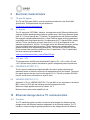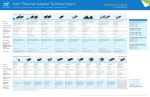
1
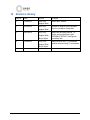
Storage: Storage device with Ethernet interface Rev 4 Author: Alvin Cox, Seagate Technology LLC Author: Asghar Riahi, Seagate Technology LLC Author: Bryan Wyatt, Seagate Technology LLC 1 Scope This specification defines the technical requirements for the storage device with Ethernet interface. 2 Contents 1 Scope ......................................................................................................................................... 2 2 Contents .................................................................................................................................... 2 3 Figures ....................................................................................................................................... 3 4 Tables ........................................................................................................................................ 3 5 Overview.................................................................................................................................... 4 5.1 Description ................................................................................................................... 4 5.2 License .......................................................................................................................... 4 6 Normative references................................................................................................................ 5 7 Definitions, symbols, abbreviations, key words ........................................................................ 5 8 7.1 Definitions .................................................................................................................... 5 7.2 Symbols and abbreviations .......................................................................................... 5 7.3 Key words ..................................................................................................................... 5 7.4 Editorial conventions.................................................................................................... 6 Mechanical characteristics ........................................................................................................ 6 8.1 9 Device and system connectors ..................................................................................... 6 Electrical characteristics .......................................................................................................... 10 9.1 TX and RX signals ........................................................................................................ 10 9.2 I2C signals .................................................................................................................... 10 9.3 +5V and +12V ............................................................................................................. 10 9.4 PRESENCE DETECT (P1)............................................................................................... 10 9.5 VENDOR SPECIFIC (P11).............................................................................................. 10 10 Ethernet storage device I2C communication ........................................................................... 10 10.1 Overview ................................................................................................................... 10 10.2 Command formats...................................................................................................... 11 10.3 Open Commands ........................................................................................................ 13 10.4 I2C implementation requirements ............................................................................. 21 11 FAQ .......................................................................................................................................... 23 Open Compute Project Storage: Storage device with Ethernet interface 12 Revision History ....................................................................................................................... 24 3 Figures Figure 1 Device Free (Plug) connector ...................................................................................... 7 Figure 2 2.5” hard disk drive with Ethernet interface plug connector ......................................... 7 Figure 3 3.5” hard disk drive with Ethernet interface plug connector ......................................... 8 Figure 4 System Backplane Fixed (Receptacle) connector ....................................................... 8 4 Tables Table 1 Connector signal assignments...................................................................................... 9 Table 2 Open I2C commands for the storage device with Ethernet interface ...........................13 Table 3 Get Device IP Address Parameter Byte Format ..........................................................15 Table 4 Get IP Address Status Byte Format .............................................................................15 Table 5 Get IP Address Returned Bytes Format ......................................................................16 Table 6 Network Speed Integer Definition ................................................................................16 Table 7 Network Speeds Available Bit Field .............................................................................17 Table 8 Get Device Operating State Bit Description .................................................................17 Table 9 Get Write Status Info Byte Definition ...........................................................................18 Table 10 Set Device IP Address Config Byte Format ...............................................................19 Table 11 Set Device IP Address Parameter Bytes Format .......................................................20 Table 12 Get Interface Link State Returned Bytes Format .......................................................21 Table 13 Get Data Protocol Version Protocol Enumeration ......................................................21 http://opencompute.org 3 5 Overview 5.1 Description The storage device with Ethernet interface provides a common configuration for the implementation of the Ethernet interface on a storage device. It is intended to support large configurations of storage devices in data center applications. Other applications may find the features of this device advantageous where communication to the device through the Ethernet interface is desired. Some example implementations are documented in <Reference to the white paper>. 5.2 License As of December 20, 2013, the following persons or entities have made this Specification available under the Open Web Foundation Final Specification Agreement (OWFa 1.0), which is available at http://www.openwebfoundation.org/legal/the-owf-1-0agreements/owfa-1-0: Seagate Technology LLC You can review the signed copies of the Open Web Foundation Agreement Version 1.0 for this Specification at http://opencompute.org/licensing/, which may also include additional parties to those listed above. Your use of this Specification may be subject to other third party rights. THIS SPECIFICATION IS PROVIDED "AS IS." The contributors expressly disclaim any warranties (express, implied, or otherwise), including implied warranties of merchantability, non-infringement, fitness for a particular purpose, or title, related to the Specification. The entire risk as to implementing or otherwise using the Specification is assumed by the Specification implementer and user. IN NO EVENT WILL ANY PARTY BE LIABLE TO ANY OTHER PARTY FOR LOST PROFITS OR ANY FORM OF INDIRECT, SPECIAL, INCIDENTAL, OR CONSEQUENTIAL DAMAGES OF ANY CHARACTER FROM ANY CAUSES OF ACTION OF ANY KIND WITH RESPECT TO THIS SPECIFICATION OR ITS GOVERNING AGREEMENT, WHETHER BASED ON BREACH OF CONTRACT, TORT (INCLUDING NEGLIGENCE), OR OTHERWISE, AND WHETHER OR NOT THE OTHER PARTY HAS BEEN ADVISED OF THE POSSIBILITY OF SUCH DAMAGE. 4 6 November, 2014 Open Compute Project Storage: Storage device with Ethernet interface 6 Normative references Referenced standards and specifications contain provisions that, by reference in the text, constitute provisions of this specification. I2C-bus specification and user manual, Rev. 5 — 9 October 2012 Serial-GMII Specification RFC 2119, RFC Key Words SFF-8201, 2.5" Drive Form Factor Drive Dimensions SFF-8301, 3.5" Drive Form Factor Drive Dimendions SFF-8223, 2.5" Drive Form Factor with Serial Connector SFF-8323, 3.5" Drive Form Factor with Serial Connector SFF-8482, Serial Attachment 2X Unshielded Connector SFF-8680, Serial Attachment 12 Gb/s 2X Unshielded Connector SFF-9639, Multifunction 12 Gb/s 6X Unshielded Connector Pinouts 7 Definitions, symbols, abbreviations, key words 7.1 Definitions 7.2 Symbols and abbreviations Abbreviation GPIO I2C mA RX TX V 7.3 Meaning general purpose input/output Inter-Integrated Circuit milliampere (i.e., 10-3 amperes) Receiver Transmitter Volt Key words The key words "MUST", "MUST NOT", "REQUIRED", "SHALL", "SHALL NOT", "SHOULD", "SHOULD NOT", "RECOMMENDED", "MAY", and "OPTIONAL" in this document are to be interpreted as described in RFC 2119. MAY This word, or the adjective "OPTIONAL", mean that an item is truly optional. One vendor may choose to include the item because a particular marketplace requires it or because the vendor feels that it enhances the product while another vendor may omit the same item. An implementation which does not include a particular option MUST be prepared to interoperate with another implementation which does include the option, though perhaps with reduced functionality. In the same vein an implementation which does include a particular option MUST be prepared to interoperate with another implementation which does not include the option (except, of course, for the feature the option provides.) MUST This word, or the terms "REQUIRED" or "SHALL", mean that the definition is an absolute requirement of the specification. MUST NOT This phrase, or the phrase "SHALL NOT", mean that the definition is an absolute prohibition of the specification. http://opencompute.org 5 SHOULD This word, or the adjective "RECOMMENDED", mean that there may exist valid reasons in particular circumstances to ignore a particular item, but the full implications must be understood and carefully weighed before choosing a different course. SHOULD NOT This phrase, or the phrase "NOT RECOMMENDED" mean that there may exist valid reasons in particular circumstances when the particular behavior is acceptable or even useful, but the full implications should be understood and the case carefully weighed before implementing any behavior described with this label. VENDOR SPECIFIC Something (e.g., a bit, field, code value) that is not defined by this specification and MAY be used differently in various implementations. 7.4 Editorial conventions Certain words and terms used in this specification have a specific meaning beyond the normal English meaning. These words and terms are defined either in the glossary or in the text where they first appear. Lists sequenced by lowercase or uppercase letters show no ordering relationship between the listed items. Lists sequenced by numbers show an ordering relationship between the listed items. If a conflict arises between text, tables, or figures, the order of precedence to resolve the conflicts is text; then tables; and finally figures. Not all tables or figures are fully described in the text. Tables show data format and values. Notes and examples do not constitute any requirements for implementers and notes are numbered consecutively throughout this specification. 8 Mechanical characteristics 8.1 Device and system connectors 8.1.1 Storage device connector The storage device with Ethernet interface plug connector is the Device Free (Plug) connector defined in SFF-8482 and SFF-8680. See the SFF specifications for detailed dimensional requirements. Figure 1 illustrates the interface plug connector. 6 6 November, 2014 Open Compute Project Storage: Storage device with Ethernet interface Figure 1 Device Free (Plug) connector 8.1.2 Device form factor and connector location The storage device with Ethernet interface form factor SHALL comply with SFF-8201 or SFF-8301 (2.5” and 3.5” drive form factors, respectively). See SFF-8223 and SFF-8323 for the storage device with Ethernet interface plug connector locations on 2.5” and 3.5” drive form factors, respectively. These SFF specifications define the location of the connector relative to the device side mounting holes and the device bottom mounting holes, as applicable. Figure 2 illustrates the connector on a 2.5” hard disk drive. The connector location on the storage device with Ethernet interface SHALL comply with the applicable SFF specification. Figure 2 2.5” hard disk drive with Ethernet interface plug connector Figure 3 illustrates the connector on a 3.5” hard disk drive. http://opencompute.org 7 Figure 3 3.5” hard disk drive with Ethernet interface plug connector 8.1.3 System connector The system backplane receptacle connector is the Backplane Fixed (Receptacle) connector defined in SFF-8482 and SFF-8680. The backplane receptacle connector defined by SFF-8639 MAY also be used. Figure 4 illustrates the SFF-8482/SFF-8680 system Fixed (Receptacle) connector. Figure 4 System Backplane Fixed (Receptacle) connector 8.1.4 Connector pin assignment Table 1 defines the system and device connector pin signal assignments. The storage device with Ethernet interface SHALL comply with this pin assignment. Other interfaces use common form factors and connectors that MAY physically mate with the device or system connector used 8 6 November, 2014 Open Compute Project Storage: Storage device with Ethernet interface in the storage device with Ethernet interface. See SFF-9639 for a list of these interfaces and pin signal assignments. Table 1 Connector signal assignments Power Signal Segment 1. 2. 3. 4. Pin Backplane receptacle Device plug S1 GROUND GROUND S2 TX0+ RX0+ S3 TX0- RX0- S4 GROUND GROUND S5 RX0- TX0- S6 RX0+ TX0+ S7 GROUND GROUND S8 GROUND GROUND S9 TX1+ RX1+ S10 TX1- RX1- S11 GROUND GROUND S12 RX1- TX1- S13 RX1+ TX1+ S14 GROUND GROUND P1 PRESENCE DETECT PRESENCE DETECT P2 I2C CLOCK I2C CLOCK P3 I2C DATA I2C DATA P4 GROUND GROUND P5 GROUND GROUND P6 GROUND GROUND P7 +5V PRECHARGE +5V PRECHARGE P8 +5V +5V P9 +5V +5V P10 GROUND GROUND P11 VENDOR SPECIFIC VENDOR SPECIFIC P12 GROUND GROUND P13 +12V PRECHARGE +12V PRECHARGE P14 +12V +12V P15 +12V +12V See 9.1 for TX and RX electrical characteristics.. See 9.2 for I2C electrical characteristics. See 9.3 for +5V and +12V requirements. See 9.4 for P1 and P11 electrical characteristics. http://opencompute.org 9 9 Electrical characteristics 9.1 TX and RX signals The TX and RX signals SHALL meet the requirements defined by the Serial-GMII Specification. This specification may be obtained at ftp://ftp-eng.cisco.com/smii/sgmii.pdf 9.2 I2C signals The I2C signals are OPTIONAL, however, a storage device with Ethernet interface that supports multiple speeds provides maximum performance if the Device Network Speed (see 10.3.11) is set through the I2C interface. (A storage device with Ethernet interface that supports multiple speeds defaults to 1 Gbps Ethernet speed, providing backwards compatibility with single speed devices.) If implemented, the I2C signals SHALL comply with the I2C-bus specification and user manual at VDD of 3.3V and operation at the standard mode speed of 100 kHz. The storage device with Ethernet interface is a slave device and lacks internal pull-up resistors. These resistors are omitted to allow the greatest flexibility when implementing shared bus. The host device SHOULD include pull-up resistors that meet the guidelines of the I2C specification. The I2C specification and user manual may be obtained at www.nxp.com/documents/user_manual/UM10204.pdf. 9.3 +5V and +12V The storage device with Ethernet interface MAY require +5V, +12V, or both +5V and +12V. See the device product data sheet for specific voltage and power requirements. 9.4 PRESENCE DETECT (P1) The P1 signal is a bidirectional signal that MAY be used to assign unique device addresses and/or to detect the removal of a storage device from the chassis. The use of this signal requires the host to pull-up the signal to 3.3V. The pull-up resistor SHOULD result in a sink current of less than or equal to 8 mA. 9.5 VENDOR SPECIFIC (P11) Application of P11 is VENDOR SPECIFIC. This pin MAY be not connected or the device MAY connect a GPIO with the following electrical characteristic limits: Maximum voltage applied to device by chassis: 3.6 V Minimum device sink current capability: 8 mA 10 Ethernet storage device I2C communication 10.1 Overview The I2C interface provides a means of communication between the chassis and the storage device with Ethernet interface independent of the Ethernet interface. The I2C interface is used to configure operating elements of the storage device with Ethernet 10 6 November, 2014 Open Compute Project Storage: Storage device with Ethernet interface interface and to communicate information about the device to the chassis. The storage device with Ethernet interface is designed to behave as an I2C Slave device at a device address of 0x2F. There are two types of commands that the storage device with Ethernet interface responds to: a) Set Commands that send data to the storage device with Ethernet interface; b) Get Commands that return data from the storage device with Ethernet interface. 10.2 Command formats 10.2.1 Set Command format (byte) Write 1. Length byte 2. Opcode byte 3. Payload byte(s) (if required) 4. Checksum byte 10.2.2 Get Command format (byte) Dummy Write 1. Length byte 2. Opcode byte 3. Payload byte(s) (if required) 4. Checksum byte Delay (Minimum of 100 microsecond) 1. 2. 3. 4. Read Length byte Opcode byte Payload byte(s) Checksum byte 10.2.3 Length An unsigned integer that indicates the number of bytes being sent in a specific transmission. This number includes the length byte itself, opcode, payload, and the checksum byte. 10.2.4 Opcode In the case of write transactions, this byte indicates the operation requested. For read transactions, this is a validation byte that SHOULD match the operation that requested data be returned. See section 10.3 for details on the assigned opcodes. http://opencompute.org 11 10.2.5 Payload For set commands the payload is typically the parameters being set, although not every set operation requires parameters. Get commands can make use of the payload field on the dummy write as a parameter to indicate what data to return, or on the read portion of the transaction, which consists of the data requested by the get operation. All integers greater than 8 bits follow big endian format. 10.2.6 Checksum format Appended to the end of every transaction is a single byte checksum. This checksum takes the form of a modular sum where each character is summed as if it were an unsigned integer. Overflow bits are discarded and the two’s complement of the final sum is appended as the checksum byte. Validation of the data MAY be accomplished by summing the characters in the same fashion, including the checksum. Valid data SHOULD result in a sum of zero. A nonzero result indicates an invalid message. 10.2.7 Delay requirements Discrete Stop and Start conditions SHOULD be issued between any two transactions rather than a repeated start, which is not supported. In addition a 100 µs delay SHOULD be placed between any two transactions to ensure no reads or writes are lost. 12 6 November, 2014 Open Compute Project Storage: Storage device with Ethernet interface 10.3 Open Commands 10.3.1 Commands overview I2C commands for the storage device with Ethernet interface are listed in Table 2. See referenced paragraphs for detailed descriptions. The commands are split into two ranges. 0x00 - 0x7f are reserved for Open Commands. 0x80 - 0xff are reserved for Vendor Specific Commands. This section defines Open Commands. Table 2 Open I2C commands for the storage device with Ethernet interface Opcode http://opencompute.org Name 0x00 Extended command set 0x01 Get Extended Status 0x02 Get Manufacturer 0x03 Get Product ID 0x04 Set Device Present 0x05 Identify Device 0x06 Get Device Temperature 0x07 Set Device I2C Address 0x08 Get Device IP Address 0x09 Set Device Network Speed 0x0a Get Device Network Speed 0x0b Get Device Operating State 0x0c Enable External Loopback 0x0d Get Write Status 0x0e Get Command Set Version 0x0f Disable External Loopback 0x10 Reset Device 0x11 Reset Interface 0x12 Set Device IP Address 0x13 Get Device Network MAC 0x14 Get Interface Link State 0x15 Get Firmware Version 0x16 Get Data Protocol Version 13 10.3.2 Extended command set (Opcode 0x00) Description: This opcode is reserved for the future implementation of an extended command set. 10.3.3 Get Extended Status (Opcode 0x01) Type: Get Bytes Returned: 0-31 (Extended Status) Description: Returns a value 32 bytes in length. The format of the returned value is vendor specific. This command SHOULD be used when the value returned by Device Operating State command indicates that Extended Status is available. 10.3.4 Get Manufacturer (Opcode: 0x02) Type: Get Bytes Returned: 0 - 15 (Manufacturer) Description: Returns a 16 byte ASCII string indicating the manufacturer of the storage device with Ethernet interface. 10.3.5 Get Product ID (Opcode: 0x03) Type: Get Bytes Returned: 0 - 15 (Model Number) Description: Returns a 16 byte ASCII string indicating the model number of the storage device with Ethernet interface. 10.3.6 Set Device Present (Opcode: 0x04) Type: Set Description: This command facilitates the detection of a device being removed from the system. In its default state the PRESENCE DETECT signal on pin P1 of the connector is high. If the command is sent to an attached storage device with Ethernet interface, then the storage device with Ethernet interface drives the PRESENCE DETECT signal low on pin P1 of the connector signal low until it is physically removed, powered down, or the device is reset. 10.3.7 Identify Device (Opcode 0x05) Type: Get Bytes Returned: 0 - 7 (WWN) Description: Returns the 64-bit Worldwide Name of the storage device with Ethernet interface. 10.3.8 Get Device Temperature (Opcode 0x06) Type: Get Byte Returned: 0 (Degrees Celsius) 14 6 November, 2014 Open Compute Project Storage: Storage device with Ethernet interface Description: Returns a single byte signed integer (2’s complement), indicating the storage device with Ethernet interface temperature in degrees Celsius. 10.3.9 Set Device I2C Address (Opcode 0x07) Type: Set Parameter Byte: 0 (Address) Description: In the case where multiple storage devices with Ethernet interface are attached to the same I2C bus, this mechanism allows the default 7-bit address of 0x2f to be changed to a unique value. In addition, the storage device with Ethernet interface is set to the Present state. This command is only acted upon if the PRESENCE DETECT signal is driven low by the host. Since 7-bit addressing is used, the MSB of the address parameter is ignored. 10.3.10 Get Device IP Address (Opcode 0x08) Type: Get Parameter Bytes: 0 (Interface Select), 1 (Address Select) Bytes Returned: 0 (Interface), 1 (Status), 2-18 (Address) Description: Returns the IP address and netmask, or gateway address, as specified in the parameter bytes, of the attached storage device with Ethernet interface. The Interface Select and Interface bytes are both unsigned integers, indicating a specific network interface. The octets and hextets are numbered from left to right, in increasing order. Hextet is used in this context to indicate a 16-bit word. Table 3 Get Device IP Address Parameter Byte Format Byte Bit Setting 0 0-7 Interface Select (Unsigned Integer) 1 2-7 Reserved 1 1 IP Version (0 = IPv4, 1 = IPv6) 1 0 Get Gateway (0 = No, 1 = Yes) Table 4 Get IP Address Status Byte Format Bit 5–7 http://opencompute.org Setting Reserved 4 Interface Configured (0 = No, 1 = Yes) 3 Static Configuration Set (0 = No, 1 = Yes) 2 DHCP Configuration Set (0 = No, 1 = Yes) 1 IP Version (0 = IPv4, 1 = IPv6) 0 Get Gateway (0 = No, 1 = Yes) 15 Table 5 Get IP Address Returned Bytes Format Byte Description (eth0) Byte 0 Interface (Unsigned Integer) 1 Status Byte (see Table 4) 2 IPv4 Octet 1 | 3 IPv4 Octet 2 | IPv6 Hextet 1 (H) 4 IPv4 Octet 3 | IPv6 Hextet 1 (L) 5 IPv6 Hextet 2 (H) 10.3.11 Description (eth1) IPv4 Octet 4 | IPv6 Hextet 2 (L) 6 IPv4 Netmask Octet 1 | IPv6 Hextet 3 (H) 7 IPv4 Netmask Octet 2 | IPv6 Hextet 3 (L) 8 IPv4 Netmask Octet 3 | IPv6 Hextet 4 (H) 9 IPv4 Netmask Octet 4 | IPv6 Hextet 4 (L) 10 IPv6 Hextet 5 (H) 11 IPv6 Hextet 5 (L) 12 IPv6 Hextet 6 (H) 13 IPv6 Hextet 6 (L) 14 IPv6 Hextet 7 (H) 15 IPv6 Hextet 7 (L) 16 IPv6 Hextet 8 (H) 17 IPv6 Hextet 8 (L) 18 IPv6 Netmask Set Device Network Speed (Opcode 0x09) Type: Set Parameter Bytes: 0 (Interface Select), 1 (Speed) Description: This command sets the network interface speed of the specified network interface on the storage device with Ethernet interface. Both the Interface Select and Speed bytes are unsigned integers, representing the network interface and network speed respectively. The Speed integer is defined in Table 6. Table 6 Network Speed Integer Definition Value 16 Speed 3 – 256 Reserved 2 10 Gbps 1 2.5 Gbps 0 1 Gbps 6 November, 2014 Open Compute Project Storage: Storage device with Ethernet interface 10.3.12 Get Device Network Speed (Opcode 0x0a) Type: Get Parameter Byte: 0 (Interface Select) Bytes Returned: 0 (Interface), 1, 2 (Speeds Available), 3 (Current Speed) Description: Returns the network speed capabilities and current setting of the specified network interface on the attached storage device with Ethernet interface. The Interface Select and Interface bytes are both unsigned integers, which should match if the data is valid. The Current Speed byte uses the same form detailed in Table 6 to indicate the currently selected speed. Two bytes take the form of a bit field, defined in Table 7, to represent the network Speeds Available. Table 7 Network Speeds Available Bit Field Bit 10.3.13 Speed 3 – 15 Reserved 2 10 Gbps 1 2.5 Gbps 0 1 Gbps Get Device Operating State (Opcode 0x0b) Type: Get Bytes Returned: 0, 1 (Error type) Description: Returns the operating state of the storage device. If the Extended Status available bit is set, then the Extended Status MAY be read with the Extended Status command set. When the Extended Status is read the Extended Status Available bit is cleared. Bit Description: See Error! Reference source not found. Table 8 Get Device Operating State Bit Description Bit 2 – 15 10.3.14 Status Reserved 1 Loopback Enabled 0 Extended Status Available Enable External Loopback (Opcode 0x0c) Type: Set Description: This command explicitly enables the external loopback mode of the storage device with Ethernet interface. While in this mode the storage device with Ethernet interface SGMII interfaces retransmit any packet received on that interface. This command is ignored if the loopback is enabled. http://opencompute.org 17 10.3.15 Get Write Status (Opcode 0x0d) Type: Get Bytes Returned: 0, 1 (Status Info), 2 (Opcode) Description: Returns an unsigned 16-bit integer and a 1 byte Opcode. This value MAY be used to determine whether or not the command was successful. The opcode returned is that of the write that this status applies to. Table 9 Get Write Status Info Byte Definition Value 4 – 65535 10.3.16 Status Reserved 3 Unrecognised Command 2 Length Mismatch 1 Checksum Mismatch 0 Success Get Command Set Version (Opcode 0x0e) Type: Get Bytes Returned: 0 (Major Revision Number), 1 (Minor Revision Number), 2 (Sub-minor Revision Number) Description: Returns three bytes, all unsigned integers. The first byte returned is the major revision number, the second is the minor revision number, and the third is the subminor. This offers a method of determining the supported commands of a specific storage device with Ethernet interface. 10.3.17 Disable External Loopback (Opcode 0x0f) Type: Set Description: This command explicitly disables the external loopback mode of the storage device with Ethernet interface. Once disabled, the storage device with Ethernet interface resumes normal network behavior. This command is ignored if the loopback mode is disabled. 10.3.18 Reset Device (Opcode 0x10) Type: Set Description: This command MAY be used to request a soft reset of the storage device with Ethernet interface. 10.3.19 Reset Network Interface (Opcode 0x11) Type: Set Parameter Byte: 0 (Interface Select) 18 6 November, 2014 Open Compute Project Storage: Storage device with Ethernet interface Description: This command MAY be used to reset the specified interface. The interface is brought down and then brought back up, restoring the saved configuration for that interface. In the case where the interface is set for DHCP, a fresh DHCP request will be made, and for static configurations the configured IP address, Netmask and Gateway will be reinstated. The parameter for this command is a single byte unsigned integer, the value determining the interface to reset. Parameter values specifying interfaces that do not exist on the storage device with Ethernet interface cause the command to be ignored. 10.3.20 Set Device IP Address (Opcode 0x12) Type: Set Parameter Bytes: 0 (Interface Select), 1 (Config), 2-18 (Address) Description: This command MAY be used to set the IP address of the specified network interface on the storage device with Ethernet interface. Byte 0, detailed in Table 10, is a bit field used to specify a protocol version, an assignment type, set a gateway address, and provides a means to clear previous settings. The Clear Settings bit, if set, will remove all currently set configuration options for the specified interface, shutting off that interface. If the Clear Settings bit is not set, the command will modify the existing configuration, only changing the specified interface and IP version settings (i.e. Setting a static IPv4 address on eth1 will not change eth0’s configuration or the IPv6 configuration on eth1). The Set Gateway bit, if set, allows a static gateway to be specified if the Assignment Type bit is also set. When specifying a gateway address, an IPv4 address should be located in address bytes 1-4, and IPv6 gateways should be located in address bytes 1-16. The Interface Select byte is a unsigned integer used to specify the interface desired. There are 17 address parameter bytes, in the case of Clear Settings being set, a DHCP configuration being set, setting a gateway address, or an IPv4 static address being set, the unused address bytes should be zero filled. Once modifications to an interface’s IP configuration are complete, the interface must be reset for the new configuration to become active. An overview of the Parameter bytes can be found in Table 11. Table 10 Set Device IP Address Config Byte Format Bit 4–7 http://opencompute.org Setting Reserved 3 Clear Settings(0 = Modify, 1 = Clear) 2 Assignment Type (0 = DHCP, 1 = Static) 1 IP Version (0 = IPv4, 1 = IPv6) 0 Set Gateway (0 = No, 1 =Yes) 19 Table 11 Set Device IP Address Parameter Bytes Format Byte Description (eth0) Byte 0 Interface (Unsigned Integer) 1 Status Byte (see Table 4) 2 IPv4 Octet 1 | 3 IPv4 Octet 2 | IPv6 Hextet 1 (H) 4 IPv4 Octet 3 | IPv6 Hextet 1 (L) 5 IPv6 Hextet 2 (H) 10.3.21 Description (eth1) IPv4 Octet 4 | IPv6 Hextet 2 (L) 6 IPv4 Netmask Octet 1 | IPv6 Hextet 3 (H) 7 IPv4 Netmask Octet 2 | IPv6 Hextet 3 (L) 8 IPv4 Netmask Octet 3 | IPv6 Hextet 4 (H) 9 IPv4 Netmask Octet 4 | IPv6 Hextet 4 (L) 10 IPv6 Hextet 5 (H) 11 IPv6 Hextet 5 (L) 12 IPv6 Hextet 6 (H) 13 IPv6 Hextet 6 (L) 14 IPv6 Hextet 7 (H) 15 IPv6 Hextet 7 (L) 16 IPv6 Hextet 8 (H) 17 IPv6 Hextet 8 (L) 18 IPv6 Netmask Get Device Network MAC (Opcode 0x13) Type: Get Parameter Byte: 0 (Interface Select) Bytes Returned: 0 (Interface), 1-6 (MAC) Description: This command returns the MAC of the specified network interface on the storage device with Ethernet interface. The Interface Select and Interface bytes are unsigned integers indicating the network interface. The MAC bytes contain the 48-bit code specific to the selected interface, if an invalid interface is selected the code will be all zeroes. 10.3.22 Get Interface Link State (Opcode 0x14) Type: Get Parameter Byte: 0 (Interface Select) Bytes Returned: 0 (Interface), 1 (Status) Description: This command returns the link state of the specified network interface on the storage device with Ethernet interface. The Interface Select and Interface bytes are both unsigned integers indicating the network interface, and the Status byte is defined in Table 12. 20 6 November, 2014 Open Compute Project Storage: Storage device with Ethernet interface Table 12 Get Interface Link State Returned Bytes Format 10.3.23 Byte Bit 0 0–7 1 1-7 1 0 Setting Interface (Unsigned Integer) Reserved Link (0 = Down, 1 = Up) Get Firmware Version (Opcode 0x15) Type: Get Bytes Returned: 0 (Major Revision Number), 1 (Minor Revision Number), 2 (Sub-minor Revision Number) Description: This command returns three bytes, all unsigned integers, indicating the version of firmware currently installed upon the storage device with Ethernet interface. The first byte returned is the major revision number, the second is the minor, and the third is the sub-minor. 10.3.24 Get Data Protocol Version (Opcode 0x16) Type: Get Bytes Returned: 0 (Major Revision Number), 1 (Minor Revision Number), 2 (Sub-minor Revision Number), 3, 4 (Protocol) Description: This command returns 5 bytes, 3 unsigned 8-bit integers, and 1 16-bit unsigned integer. The first byte returned is the major revision number, the second is the minor, the third is the sub-minor, and the remaining two bytes are an integer code used to indicate the specific protocol used by the storage device with Ethernet interface. Table 13 defines the Protocol integer. Table 13 Get Data Protocol Version Protocol Enumeration Value 1 – 65535 0 Status Reserved Kinetic 10.4 I2C implementation requirements 10.4.1 I2C signals See 9.2 10.4.2 Clock stretching Host devices need to support clock stretching. It is expected that storage device with Ethernet interface make use of clock stretching. Failure to properly handle clock stretching MAY lead to corrupt transactions due to a loss of synchronization between the Master and Slave. http://opencompute.org 21 10.4.3 Power down isolation A storage device with Ethernet interface in the powered down state SHOULD NOT interfere with the I2C communication between the host and other devices. Some I2C controllers MAY require additional circuitry to isolate the I2C clock and data signals so the storage device with Ethernet interface does not load the bus when the storage device with Ethernet interface not powered. This is an issue that needs to be addressed by the storage device with Ethernet interface. 22 6 November, 2014 Open Compute Project Storage: Storage device with Ethernet interface 11 FAQ Q: Is there any software needed (Driver’s etc.)? A: The storage device with Ethernet interface uses standard Ethernet communication protocols Q: Is there a physical keying mechanism to prevent insertion of the storage device with Ethernet interface in a SAS/SATA slot or vice versa? If not, can this cause damage to the system? A: There is no physical keying mechanism to distinguish between different drive types. Signal locations and protocol prevent damage to the system and the device. Q: How are the drives presented on the network? A: Each drive has two IP addresses. For additional FAQ regarding the Storage device with Ethernet interface refer to wiki FAQ: https://developers.seagate.com/display/KV/FAQ http://opencompute.org 23 12 Revision History Version Date Author Changes 1 12/20/2013 Alvin Cox, Initial Public Version Asghar Riahi 2 04/10/2014 Alvin Cox, Asghar Riahi 3 08/21/2014 Alvin Cox, Asghar Riahi, Bryan Wyatt 4 11/06/2014 Alvin Cox, Asghar Riahi, Updates to address initial feedback from the Incubation Committee Added the following sections: I2C, FAQs, and revision history plus PRESENCE DETECT, and figures and tables lists. Added several new I2C Commands, updated some existing I2C commands Bryan Wyatt 24 6 November, 2014