1
Chapter 3 Interfacing
3.1.1
Status Indicators
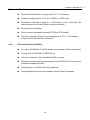
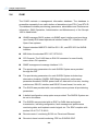
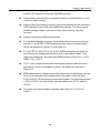
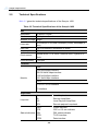
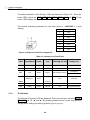
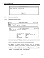
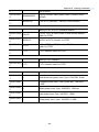
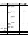
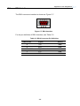
The status indicators of the Scorpio 1400 are depicted in Figure 3-2. There are
seven LEDs, which are PWR, CPE, DSL, DTE1, DTE2, ALM and TST. These
seven LEDs display the system status.
The default unlocking password for the front panel is “14001400” if it was
locking.
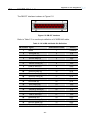
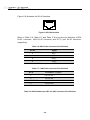
Pin
Description
1
TX+
2
TX-
3
RX+
4
NC
5
NC
6
RX-
7
NC
8
NC
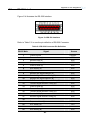
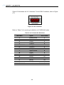
Figure 3-2 Ethernet RJ-45 Pin Assignment
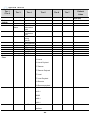
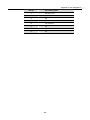
Table 3-1 Indicators on Front Panel
LED
Description
Color
Off
Flashing 0,5 sec
Always On
PWR
Power
Green
No Power
N/A
Power OK
CPE
CPE
Green
CO
N/A
CPE
DSL
Loop
Green
Failure
Handshaking/Training
Idle
Unequipped
DTE1
Data/E1/T1
Green
N/A
Traffic OK
or Failure
DTE2
3.1.2
Connecting
ALM
Alarm
Red
Normal
Major Alarm
Minor Alarm
TST
Testing
Amber
Normal
N/A
Loopback activated
The Buttons
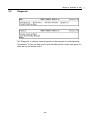
The buttons of Scorpio 1400 are depicted. There are six keys, including HOME,
REM/LOC, ▲, ▼, ◄, and ►. By pressing these buttons, users may perform
configuration, testing for setting up and diagnostic purpose.
-30-