1
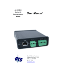
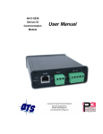
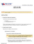
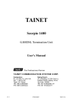
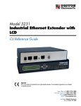
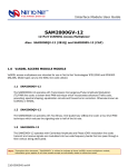
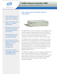
SIA2410R SHDSL Router
User Manual
Revision 1.3
Software version 3.9.2
Net To Net Technologies
Copyright © 2002 Net To Net Technologies, Inc. All rights reserved.
Tel: (603)422-0600
E-mail: [email protected]
Net To Net Technologies SIA2410R User Manual
Contents
PART I: SIA2410R Introduction ...........................................2
Introduction....................................................................................................................3
Specifications .................................................................................................................4
PART II: Installing the Router ...............................................7
Getting started ..............................................................................................................8
SIA2410R Package Contents...................................................................................9
Connecting cables......................................................................................................10
PART III: Configuring the Router ........................................12
Accessing the Console..............................................................................................13
User Mode .....................................................................................................................14
Establishing LAN Interface .....................................................................................16
Establishing WAN(SHDSL) Interface..................................................................18
Configuring the Routing Table ..............................................................................22
Configuring the ARP Table ......................................................................................26
Saving the Configuration ........................................................................................28
Rebooting the system ..............................................................................................31
PART IV: Configuring advanced Functions ...........................32
Configuring Bridge Function ..................................................................................33
Configuring DHCP Function....................................................................................36
Configuring NAT Function .......................................................................................40
Configuring VLANs and QoS ..................................................................................45
VLAN Modes..................................................................................................................45
QoS Methods................................................................................................................45
Configure Simple Network Time Protocol (SNTP) ........................................50
PART V: System maintenance ..............................................51
Accessing Telnet .........................................................................................................52
Configuring SNMP Functions .................................................................................52
Upgrading the System Software..........................................................................53
PART VI: Configuration Examples........................................56
Configuring NAT/PAT Functions............................................................................56
Appendix .............................................................................57
Connector Pin-outs ....................................................................................................57
Net To Net Technologies
1
Net To Net Technologies SIA2410R User Manual
PART I: SIA2410R Introduction
• Overview and Features
• Specifications
Net To Net Technologies
2
Net To Net Technologies SIA2410R User Manual
Introduction
Introduction to the Net To Net Technologies SIA2410R Router
Overview
The SIA2410R router with SHDSL is a full-featured, stand-alone router with
VLAN and QoS support for connecting diverse Local Area Networks (LANs) to
the Internet and other remote networks. It provides a fast SHDSL (Symmetric
High-speed Digital Subscriber Line) connection to the Internet or between
LANs.
The SIA2410R supports a packet-based network technology that
allows high-speed transmission over twisted-pair copper wire between a
DSLAM in the central office and a customer site, or on copper loops between
two sites. The SIA2410R provides a single G.SHDSL port and four Ethernet
switch ports, this allows up to four devices to be connected to the router
without the use of an external hub or switch.
Features
The SIA2410R provides the following features.
• Multiple line rates from 72kbps to 2320kbps including rate adaptive mode
when used in point to point configurations
• Interoperates with SµD2000-6/12, SMD2000G-12, SMD2000-24,
SAM2000G-12 and SIM2000-24 Net to Net products
• Integrated 4 port Ethernet switch with MID/MID-X auto sensing ports.
• LED’s on the front side for monitoring and troubleshooting
• IP routing for internet and intranet connectivity
• Various management tools. (RS232 CLI, Telnet CLI and SNMP)
• RIP1, RIP2 IP routing protocol
• Support for Network Address Translation (NAT/PAT)
• DHCP that assigns an IP address to local network nodes automatically
and dynamically
• Configuration flexibility of 802.1Q VLAN support
• Quality of Service (QoS) features including 802.1p Priority, Differentiated
Services Code Point (DSCP) – RFC#2474, and LAN Port based Priority.
• Diagnostic utilities such as Ping and Traceroute
Net To Net Technologies
3
Net To Net Technologies SIA2410R User Manual
Specifications
[Table 1-1] The SIA2410R router specification
Hardware Specifications
Line Coding Method
G.SHDSL (TCPAM, ITU G.991.2)
DSL Port (for G.SHDSL)
1 port with RJ-11
LAN Port (for Ethernet)
4 ports with RJ-45
Console Port
RS232 RJ-45
Data Rate
WAN: 72kbps~2320kbps
LAN: 10/100Mbps auto negotiating
Power
External Adapter 5V 2.0A
Dimension
230mm(W) x 165mm(D) x 35mm(H)
Software Specifications
LAN
IP
WAN
NTNHDLC
Routing
RIP I, RIP II
Management
SNMPv1 (MIB I, MIB II), http NMS, CLI
VLAN
802.1Q
QoS
802.1p Priority
DiffServ (DSCP) RFC 2474
Port based Priority
Application
TELNET RFC 854
DHCP RFC 1531
NAT/PAT
IP Filter
TFTP software upgrade
Net To Net Technologies
4
Net To Net Technologies SIA2410R User Manual
The front side of the SIA2410R Router
The Net To Net Technologies SIA2410R router has various LED’s on the front
panel to provide port status and diagnostic information.
[Figure 1-2] The front side of the SIA2410R
Net to Net
Technologies
POWER
ACT COL
LINK
SYNC TX RX
[Table 1-2] LED Descriptions
LED
STATUS
POWER
ON/OFF
ACT
Blink
NOT USED
COL
ON/OFF
NOT USED
LINK
ON/OFF
LAN port physical cable connection status
SYNC
ON/OFF
DSL port G.SHDSL synchronization status
TX
Blink
DSL port data transmitting
RX
Blink
DSL port data receiving
Net To Net Technologies
DESCRIPTION
Power ON/OFF
5
Net To Net Technologies SIA2410R User Manual
The rear panel of the SIA2410R Router
Sockets for the Power, LAN, Console and DSL connections in addition to the
ON/OFF switch are located on the rear panel of the SIA2410R.
[Figure 1-4] The rear side of the SIA2410R router
LAN
ON OFF
DC5V
1
2
3
4
CONSOLE
DSL
[Table 1-3] Port Descriptions
Port
DC 5V
CONSOLE
(RJ-45 to DB9)
Explanation
Connection to the 5V DC mains adapter
Serial port for connection to an RS-232 serial port of a PC (e.g.
COM 1).
LAN
(RJ-45)
Provides 4 Ethernet ports for connectivity to PCs and network
devices.
DSL
(RJ-11)
Connect a pair of copper wires for G.SHDSL connection, tip
and ring are on center two pins of the RJ-11 jack (6pin
connector)
Earth Ground
Lug
An earth ground connection is provided if required.
Net To Net Technologies
6
Net To Net Technologies SIA2410R User Manual
PART II: Installing the Router
•
•
•
Getting Started
Package Contents
Connecting Cables
Net To Net Technologies
7
Net To Net Technologies SIA2410R User Manual
Getting started
Check the items below before you begin.
Physical Environments
To ensure reliable operation of the SIA2410R a suitable location must be
chosen which meets the following environmental conditions:
•
Operating Temperature: 0ºC to 50ºC
•
Operating Relative Humidity: 5% to 95% (non-condensing)
Required Parameters
The SIA2410R needs to be configured with various parameters to enable
network connectivity, if you are uncertain of these please contact your
network administrator or service provider.
For basic operation the following values will be needed:
•
WAN IP address and subnet mask
•
LAN IP address and subnet mask
•
Default gateway IP address
•
Primary and secondary domain name server (DNS) IP address
Net To Net Technologies
8
Net To Net Technologies SIA2410R User Manual
SIA2410R Package Contents
Package Contents
Following items are needed for the set up of the Net To Net Technologies
SIA2410R Router:
•
Power cable and AC/DC adapter
•
UTP CAT 5 Ethernet cable with RJ-45 connectors for LAN connection
•
Console cable (RJ-45 to DB9 connector)
•
Telco cable with RJ-11 (use center pins) for SHDSL connection
The SIA2410R package should contain the following items:
[Table 2-1] Net To Net Technologies SIA2410R router package:
Item
Quantity
SIA2410R
1
Router
Power Cable
1
Country specific mains lead
Power Adapter
1
AC/DC adapter (DC 5V)
Console Cable
1
RJ-45 to DB-9 pin serial cable
UTP Cable
1
For a Local Area Network (LAN) connection
Documentation
1
This Guide
Net To Net Technologies
Description
9
Net To Net Technologies SIA2410R User Manual
Connecting cables
This section explains the physical set up for the Net To Net Technologies
SIA2410R router.
Connecting Power Cables
1. Plug the AC/DC adapter into the mains outlet.
2. Plug the other end of the AC/DC power adapter into the port named
"DC5V" in the back of the SIA2410R unit.
3. Switch the power switch to the ON position.
4. Confirm if the LED named "POWER" is illuminated on the front panel.
Note: If the LED is not on, check that the power cable is properly connected
or that the AC supply is switched on.
Connecting LAN Port
1. Connect one end of the UTP cable to the network equipment such as a
PC, switch or other network device.
2. Connect the other end of the UTP cable to one of the "LAN" ports on
the back of the SIA2410R unit.
3. Confirm if the LED named "LINK" is illuminated for the appropriate LAN
port.
Note1: If the LED is not on, check if the UTP cable is properly connected or if
there is a break in the cable.
Note2: You can use both a UTP Straight-through cable and a UTP Cross-over
cable to connect the PC or network device to the SIA2410R’s LAN port,
the port automatically adapts if a crossover connection is required.
Net To Net Technologies
10
Net To Net Technologies SIA2410R User Manual
Connecting DSL ports
1. Plug the RJ-11 connector (DSL line is connected via the centre two
pins of the RJ11 socket) into the DSL socket on the SIA2410R.
Note: The DSL ‘SYNC’ LED will be illuminated when the DSL line is
synchronized.
Net To Net Technologies
11
Net To Net Technologies SIA2410R User Manual
PART III: Configuring the Router
•
•
•
•
•
•
•
•
Accessing the Console
User Mode
Establishing LAN interface
Establishing WAN interface
Configuring the Routing Table
Configuring the ARP Table
Saving the Configuration
Rebooting the system
Net To Net Technologies
12
Net To Net Technologies SIA2410R User Manual
Accessing the Console
Connecting via the Console Port
To configure the router a serial connection needs to be made between the
SIA2410R and a PC. Connect the RJ-45 connector to the port labeled
‘CONSOLE’ on the back of the SIA2410R unit, and the other end of the cable
(DB-9 connector) to the computer’s COM port.
Run
any
communications
program
that
supports
vt100
emulation
(HyperTerminal or Zterm for example) to communicate directly with the
router through the computer’s COM port.
Note: If random or illegible characters appear on your display, the
communications settings are probably incorrect. Mask sure that your
communications software is configured as follows.
[Table 2-2] Console software parameters
PARAMETER
VALUE
Bits per Second
9600
Data Bits
8
Parity
N
Stop Bit
1
Flow Control
None
Terminal Type
VT100
Telnet Connection
Once the SIA2410R has been configured with an IP address, you may use the
IP address to open a Telnet session with the unit from any workstation on the
same network. The Net To Net Technologies SIA2410R can be configured
using a program that supports the Telnet protocol.
Net To Net Technologies
13
Net To Net Technologies SIA2410R User Manual
User Mode
The Net To Net Technologies SIA2410R supports two modes: Login Mode and
Configuration Mode. The two modes allow operators to monitor the router
without giving them access to configuration commands.
Login Mode
The Login mode only allows the user to monitor the router functions; it
does not allow configuration commands.
Activating the Login Mode:
1. Enter the password and press Enter. The default password is
‘password’:
Password : password
If you enter the correct password, the command-line prompt appears
as follows :
SIA2410R>
2. To close this mode, enter ‘exit’ at the command prompt:
SIA2410R> exit
Note: The default password must be typed in lower case. If the properly
typed default password does not work, check whether ‘Caps Lock’ is on
or not.
Configuration Mode
The Configuration mode allows all commands to be entered by the user.
To Activate the Configuration mode, type in the following command whilst in
Login mode:
1. SIA2410R> enable
2. Enter the password and press Enter. The default password is
‘password’:
Password: password
Net To Net Technologies
14
Net To Net Technologies SIA2410R User Manual
1. If you enter the correct password, the command-line prompt appears
as follows:
SIA2410R(conf)#
2. To exit the configuration mode, enter the Exit command at the prompt:
SIA2410R(conf)# exit
Note: The default password must be typed in lower case. If the properly
typed default password does not work, check whether the ‘Caps Lock’
key is pressed or not.
Changing a Password
Both the ‘login’ and the ‘configuration’ mode passwords may be
changed from the configuration mode. It is advised that both
passwords be changed as part of the configuration process to prevent
unauthorized access.
Changing a password for Login Mode.
Command
passwd
SIA2410R(conf)# passwd
Usage Examples
Enter login password:xxxx
New password:yyyy
Re-enter new password:yyyy
Changing a password for Configuration Mode.
Command
passwd config
SIA2410R(conf)# passwd config
Usage Examples
Enter config password:xxxx
New password:yyyy
Re-enter new password:yyyy
Net To Net Technologies
15
Net To Net Technologies SIA2410R User Manual
And then you must save the changes in Flash memory.
Command
write config
Note: If you lost your password, please contact Net To Net Technologies
Tel: (603) 422-0600
E-mail: [email protected] / [email protected]
Establishing LAN Interface
Assigning an IP Address to the LAN interface
Command
Parameters
Usage
Examples
interface <ifname> ip <address> <mask> [secondary]
<ifname>
<address>
<mask>
[secondary]
interface name
IP address
subnet mask
indicates a secondary IP address
(conf)# interface lan ip 168.126.188.130 255.255.255.0
(conf)# interface lan ip 192.168.3.2 255.255.255.224 secondary
Note: When adding a secondary IP address on the same interface, don’t
forget to add the string “secondary”. Otherwise, it will replace the
primary IP address with the new IP address.
Viewing configuration for the LAN interface
The following statistics are available for a given interface:
Up/Down status
MAC address
IP address
Routing or bridging mode status
Net To Net Technologies
16
Net To Net Technologies SIA2410R User Manual
To display the LAN interface configuration, use the following command:
Command
show interface [-v|-c] [<ifname>]
Parameters
-v
-c
<ifname>
shows full statistics
initializes the statistics
interface name
(conf)# show interface lan
Interface: lan, status <UP>, mtu 1500
ip address 168.126.188.130 255.255.255.0
Routing-only mode
ether 00:d0:84:01:08:b2, speed 100 Mbps full-duplex
(conf)#
Usage Examples
(conf)# show interface -v lan
---------------------------------------------------------------Interface: lan, status <UP>, mtu 1500
---------------------------------------------------------------ip address 168.126.188.130 255.255.255.0
Routing-only mode
ether 00:d0:84:01:08:b2, speed 100 Mbps full-duplex
descriptor rhead:0x921e0 thead:0x91db8 ttail:0x91db8
statistics:
10 RxOK, 0 RxNoBufs, 0 RxMiss
0 RxCRCErr, 0 RxAlignErr, 0 RxDribbles
5 TxOK, 0 TxNotReady, 0 TxTooBig
0 TxLossCRS, 0 TxLateCols, 0 TxCollisions
(conf)#
(conf)# show interface –c lan
Note: To display all interfaces, use the “show interface” command.
Deleting the secondary IP address
Command
int <ifname> delete [secondary] <address>
Parameters
<ifname>
[secondary]
<address>
Usage
Examples
interface name
indicates a secondary IP address
IP address
(conf)# int lan delete secondary 172.16.10.1
Net To Net Technologies
17
Net To Net Technologies SIA2410R User Manual
Establishing WAN(SHDSL) Interface
The SIA2410R unit supports a single SHDSL connection. The SHDSL port is
referred to as the WAN interface.
Configuring the WAN (SHDSL) port
The SHDSL port supports multiple data rates as well as a rate-adaptive
mode. Also it can act as both a COE and a CPE. The SHDSL port
supports multiple line rates ranging from 72 kbps to 2320 kbps. In rate
adaptive mode line rate is negotiated to the highest achievable data
rate, given the loop conditions, and then locked when the line trains.
To control the SHDSL physical port, use the following commands:
Command
Parameters
device <ifname> gshdsl co [auto] <kbps>
device <ifname> gshdsl rt
<ifname>
interface name
co|rt
unit type (COE or CPE), the default is CPE.
[auto]
use rate adaptive mode
<kbps>
sets a line rate in kbps from 72 to 2320
64 x N + 8 + I x 8 , N=1~36 / I=0,1
Usage example
(conf)# device wan gshdsl co 2320
(conf)# device wan gshdsl rt
(conf)# device wan gshdsl co auto 2320
Note : Once the ‘rt’ option is used to set the unit as a CPE, it is automatically
set to adaptive mode (speed set by COE).
Net To Net Technologies
18
Net To Net Technologies SIA2410R User Manual
Viewing the device configuration
To verify whether the unit type and line rate have been configured
correctly, use the following command:
Command
show device
Parameters
Usage example
(conf)# sh dev
name
type
side
speed
-------------------------------------------lan
10base-t
*
10 Mbps
wan
gshdsl
(ANNEX-A) RT
auto
(conf)#
Monitoring the SHDSL port
Use the "gshdsl" command to display the status of an SHDSL physical
port on the router.
Command
gs
Parameters
Usage examples
Net To Net Technologies
(conf)# gs
==========================================================
G.SHDSL R2.0(A.233.1.21) Device Driver, (14:25 05/15/2002)
==========================
Line #
0
==========================
Side
RT
Mode
ADAPTIVE
OP state
[Data]
SYNC status
sync
rate(kbps)
2320
Tx Power
13
LoopAtten(dB) -1
SNR(dB)
35
SMargin (dB) 2
(conf)#
19
Net To Net Technologies SIA2410R User Manual
Note1: Operating Status (OP State)
Handshake:
Local transceiver tries to reach the far-end transceiver.
Training:
Indicates the startup training is in progress.
Data:
Successfully trained.
Note2: Loop Attenuation
The difference in decibels (dB) between the power received at the near-end
and the power transmitted from the far-end.
You can verify values related the data rate using the following command :
Command
(conf)# gs status
Assigning the IP Address to the WAN interface
Command
interface <ifname> ip <address> <mask> [secondary]
<ifname>
Parameters
Usage Examples
interface name
<address>
IP address
<mask>
subnet mask
[secondary]
Indicates a secondary IP address
(conf)# interface wan ip 192.168.3.2 255.255.255.224 secondary
Net To Net Technologies
20
Net To Net Technologies SIA2410R User Manual
Setting Encapsulation
The SIA2410R must be configured to use the ‘ntnhdlc’ encapsulation
mode. This is the default setting and should not be changed.
Command
interface wan encap ntnhdlc
Usage examples
(conf)# interface wan encap ntnhdlc
Viewing configuration for the WAN interface
Up/Down status, IP address, routing or bridge mode status,
encapsulation is displayed.
To display the WAN interface configuration, use the following
command:
Command
show interface [-v|-c] [<ifname>]
Parameters
-v
-c
<ifname>
shows full statistics
initializes the statistics
interface name
(conf)# show interface wan
Usage Examples
(conf)# show interface -v wan
(conf)# show interface –c wan
Note: To display all interfaces, use “show interface” command.
Net To Net Technologies
21
Net To Net Technologies SIA2410R User Manual
Configuring the Routing Table
Setting up Static Route
A static route is a path from one network to another, which specifies
the destination network and the router to use get to that network. For
routes that must be reliable, the administrator often configures more
than one path (adds a secondary route), in which case the SIA2410R
chooses the primary route on the basis of an assigned metric.
Note: If no routes exist for the destination address of a packet, the SIA2410R
forwards the packet to the default route. If there is no default route,
the SIA2410R drops the packet.
Command
ip route add default <ifname> [<gw>] [<metric>]
ip route add <net> <mask> <ifname> [<gw>] [<metric>]
default
Adds the default route
<net> <mask>
Adds the destination network
<ifname>
Name of the interface through which a packet
addressed to this destination will be sent.
Parameters
<gw>
The address of the gateway to use for that destination
<metric>
A metric value for this route
network.
Usage
Examples
(conf)# ip route add default wan
(conf)# ip route add 210.10.10.0 255.255.255.0 lan 168.126.188.5
Note: The “ip route add” command can add multiple paths of the same
network. To overwrite a static route to that network, you must first
remove any existing route (or routes) for the same network.
Net To Net Technologies
22
Net To Net Technologies SIA2410R User Manual
Deleting the static route :
(conf)# ip route del default|all
Command
(conf)# ip route del <net> <mask> [<ifname>] [<gw>]
Parameters
default
Removes the default route
all
Removes all static routes and RIP entries
<net> <mask>
Identifies the particular routing entry
[<ifname>]
Name of the interface through which a packet addressed to
this destination will be sent.
<gw>
The address of the gateway to use for that destination
network.
(conf)# ip route del all
Usage
examples
(conf)# ip route del 210.10.10.0 255.255.255.0
(conf)# ip route del default
Viewing the Routing Table
To display information for the routing table, use the following
command.
Command
show ip route [-a]
Parameters
-a
Usage
Examples
(conf)# show ip route
destination
netmask
gateway
met ifname
type
--------------------------------------------------------------------default
*
0.0.0.0
1
wan
static
210.10.11.0
255.255.255.0
168.126.188.100 1
lan
static
168.126.188.0
255.255.255.0
168.126.188.130 0
lan
connected
Display all routes in the routing table.
Note: The SIA2410R dynamically adds a directly connected route. The value
in the type column is “connected”.
Note: Routes pointing to local machines are labeled local, with a single route
for each local IP address.
Net To Net Technologies
23
Net To Net Technologies SIA2410R User Manual
RIP (Routing Information Protocol)
A dynamic route is a path to another network that is “learned”
dynamically. A router that uses RIP broadcasts its entire routing table
every 30 seconds, updating other routers about which routes are
usable. Dynamic routes age and if no updates are received, they
eventually expire.
The SIA2410R unit supports RIP1 and RIP2, RIP1 (version I) does not
support the subnet mask information, whereas RIP2 (version II)
supports CIDR (Classless Inter-domain Route) block address, VLSM
(Variable Length Subnet Masking), route summarization, and security.
RIP is saved as a form of routing table in the internal cache. This
routing information is periodically broadcast to the neighboring routers
by means of the UDP protocol. To update its routing table the host can
receive information that has been broadcast from other routers, and it
can compare its own information with the received information to
generate optimum routing entries. RIP uses a distance vector metric,
so the metric is interpreted as a hop count.
Configuring RIP
Receiving or transmitting for RIP1 or RIP2 updates can be configured
for each interface.
Command
Parameters
Usage examples
Net To Net Technologies
rip enable <ifname> rxrip1|txrip1|rxrip2|txrip2
<ifname>
interface name
rxrip1|txrip1
receives and transmits RIP1 updates
rxrip2|txrip2
receives and transmits RIP2 updates
(conf)# rip enable wan rxrip2 txrip2
24
Net To Net Technologies SIA2410R User Manual
Disabling the RIP from the interface
Command
Parameters
Usage
rip disable <ifname> rxrip1|txrip1|rxrip2|txrip2
<ifname>
interface name
rxrip1|txrip1
receives and transmits RIP1 updates
rxrip2|txrip2
receives and transmits RIP2 updates
(conf)# rip disable wan rxrip2 txrip2
Receiving and transmitting the default gateway
The default route specifies a static route to another IP router, which is
often a local router. When the rxdefault is set to disable, RIP updates
will not change the default route entry in the SIA2410R routing table.
Command
Parameters
Usage examples
rip enable|disable <ifname> rxdefault|txdefault
<ifname>
interface name
rxdefault
receives a default gateway using RIP updates
txdefault
transmits a default gateway using RIP updates
(conf)# rip enable wan rxdefault txdefault
(conf)# rip disable wan rxdefault txdefault
Sending RIP information manually to the specified interface
Command
rip send <ifname> v1|v2
Parameters
<ifname>
Usage example
(conf)# rip send wan v2
Net To Net Technologies
Interface name
25
Net To Net Technologies SIA2410R User Manual
Viewing the RIP configuration
Displays the current RIP configuration
Command
Usage example
show rip
(conf)# sh rip
wan: txrip2 rxrip2
lan: disabled
(conf)#
Viewing the RIP updates :
Command
show ip route
Usage example
(conf)# sh ip route
destination
netmask
gateway
met ifname type
--------------------------------------------------------------------210.10.10.0
255.255.255.0
210.10.10.1
1 wan
rip(175)
168.126.188.0 255.255.255.0
168.126.188.130 0 lan
connected
(conf)#
Configuring the ARP Table
ARP (Address Resolution Protocol) is a protocol designed to acquire
information on the mapping between an IP address and a physical MAC
address. The internal cache of the router contains the ARP table for mapping
between the IP addresses and MAC addresses, this ARP table is dynamically
configured and updated with broadcast packets. The “arp” command is
available to set up fixed mapping information for the IP and MAC addresses.
Net To Net Technologies
26
Net To Net Technologies SIA2410R User Manual
Adding the ARP entry
Command
Parameters
Usage example
arp add <net address> <mac address> <ifname>
<net address>
host IP address
<mac address>
mac address (for example, 00:D0:84:00:00:01)
<ifname>
interface name
(conf)# arp add 168.126.188.133 00:d0:84:12:23:5a lan
Deleting the ARP entry
Command
arp del <net address>
Parameters
<net address>
Usage Example
(conf)# arp del 168.126.188.133
Network address (IP address)
Viewing the ARP table
Command
(conf)# show arp
Net To Net Technologies
27
Net To Net Technologies SIA2410R User Manual
Saving the Configuration
The system configuration values are saved in Flash memory, the configuration
values currently being used by the system are lost when the system is
rebooted. To prevent the system configuration values from being lost, nonvolatile memory called Flash memory is employed. If the current system
configuration values are saved in Flash memory, the previous operating
environment can be restored when the system boots up.
Saving Router Configuration Changes
The following command saves the current running configuration to
flash memory.
Command
write config
Displaying the configuration information
You can also display the configuration stored in flash memory by
using the “show config” command. This command prints out the
contents of Flash memory, which will be the snap shot configuration
of the router at the time the user did a “write config”:
Command
show config
The “show config running” command displays the configuration
information currently running on the router:
Command
show config running
Net To Net Technologies
28
Net To Net Technologies SIA2410R User Manual
Resetting to the Default Configuration
Step1: The following command resets all configuration settings to factory
defaults, including passwords and the IP address. The “write config –
default” command changes the contents of Flash memory only.
Command
write config –default
Step2: Reboot the system. After rebooting, the system will be reset to the
factory default.
Command
reboot flash
Net To Net Technologies
29
Net To Net Technologies SIA2410R User Manual
The default configuration is as follows:
SIA2410R(conf)# sh config
#
# System Configuration:
# boot status: system configuration checksum OK.
mac-address 00:d0:84:00:ff:f2
console-baudrate 9600
hostname SIA2410R
#
device local none(0)
device lan 10base-t
device wan gshdsl(annex-a) RT auto
#
interface local ip 127.0.0.1 255.0.0.0
encapsulation NULL
interface lan ip unnumbered
bridge enabled
encapsulation ETHERNET
interface wan ip unnumbered
bridge enabled
encapsulation NTNHDLC
#
#
#
#
#
#
SIA2410R(conf)#
SIA2410R(conf)# sh int
Interface: lan, status <UP>, mtu 1500
ip address unnumbered
Bridging-only mode
ether 00:d0:84:00:ff:f2, speed 100 Mbps full-duplex
Interface: wan, status <DOWN>, mtu 1500
ip address unnumbered
Bridging-only mode
encapsulation NTNHDLC, ether 00:d0:84:00:ff:f2
idle-char FLAG, RT speed -/- Kbps
SIA2410R(conf)#
Net To Net Technologies
30
Net To Net Technologies SIA2410R User Manual
Rebooting the system
Unplugging and subsequent plugging of the power source adapter for
SIA2410R triggers a reboot of the system hardware. The following command
is available to perform a software reboot of the system.
Command
reboot flash
Note: Before rebooting the system, you must save current configuration to
Flash
memory.
Otherwise,
the
system
will
lose
the
running
configuration. This is because SIA2410R router configures the system
based on the values stored in Flash memory.
Net To Net Technologies
31
Net To Net Technologies SIA2410R User Manual
PART IV: Configuring advanced Functions
•
•
•
•
•
•
Configuring
Configuring
Configuring
Configuring
Configuring
Configuring
Net To Net Technologies
Bridge Function
DHCP Function
NAT Function
IP Filter Function
VLANs and QoS Function
SNTP Function
32
Net To Net Technologies SIA2410R User Manual
Configuring Bridge Function
Bridging is useful primarily in providing connectivity for protocols other than
IP although it can be used to join segments of an IP network. Because a
bridging connection forwards packets at the hardware address level (link
layer), it does not distinguish between protocol types, and it requires no
protocol-specific network configuration.
Bridging is commonly used to:
Provide non-routed protocol connectivity with another site
Link two sites so that their nodes appear to be on the same LAN
Support protocols that depend on broadcasts to function
The SIA2410R provides the following features:
Routing-Only Mode
This mode supports only those IP routing functions that are
supported by the existing router. In general, when the IP is set in the
interface, this mode is automatically set.
Routing and Bridging Mode (Brouter)
In this mode, only IP packets are routed, and all other packets (IPX,
NetBEUI, etc.) are handled with bridging. This mode sets the bridge
function to “enable” only if the routing function is set to “enable”.
Bridging-Only Mode
This mode configures the SIA2410R as a bridge.
When setting up
this mode, the routing function defined as default must be turned to
“disable”. If not, the IP packets will not be bridged.
Note: To control the router remotely in this mode, the IP should be set in the
LAN interface. Also, the remote control of the router via the Internet
requires that a default gateway be set.
Net To Net Technologies
33
Net To Net Technologies SIA2410R User Manual
Setting up Routing-Only Mode
This mode becomes set as a default mode when setting the IP
address in the interface. This mode provides the routing services for
the IP packets. The following command is for manually setting or
deleting the routing mode.
ip routing enable <ifname>
Command
ip routing disable <ifname>
Parameters
<ifname> - Interface name
Setting up Routing and Bridging Mode
The following command is available for enabling or disabling the
bridge mode in the specified interface. Setting the bridge mode
without deleting the routing mode will trigger a setup of "Routing and
Bridging Mode".
interface <ifname> bridge enable
Command
interface <ifname> bridge disable
Parameters
Confirmation of
Setup
<ifname>
Interface name
enable
enabling the bridge mode
disable
disabling the bridge mode
(conf)# sh int
: Confirm "Routing and Bridging Mode".
Net To Net Technologies
34
Net To Net Technologies SIA2410R User Manual
Setting up Bridging-Only Mode
As described above, setting the bridge mode without deleting the
routing mode from the interface will trigger a setup of "Routing and
Bridging Mode". To set a mode to "Bridging-Only Mode", the routing
mode must be deleted.
interface <ifname> bridge enable
Command
Confirmation of
Setup
ip routing disable <ifname>
(conf)# sh int
: Confirm "Bridging-Only Mode".
Note: To operate as a bridge, you must configure "Bridging-Only Mode" to all
interfaces(LAN and WAN).
Managing the bridge table
In order to forward bridged packets to the right network destination,
the SIA2410R uses a bridge table that associates end nodes with
particular connections. It builds this table dynamically, in a process
called transparent bridging.
The following command shows the
bridge map:
Command
show bridge map
Net To Net Technologies
35
Net To Net Technologies SIA2410R User Manual
Configuring DHCP Function
The DHCP (Dynamic Host Configuration Protocol) protocol enables a DHCP
client who has not set the IP address to receive an IP address, and other host
configuration parameters, automatically.
Net To Net Technologies SIA2410R supports the following two functions: a
DHCP relay function that delivers the IP address request packet received from
the DHCP client to the specified DHCP server, and a DHCP server function that
allocates the IP address upon the receipt of the IP address request packet.
With these functions, the DHCP client can gain access to the IP network
without setting the IP address.
Setting DHCP relay service
To set up dhcp relay, you have to set the following command:
Command
dhcp relay to <server>
dhcp relay off
Parameters
<server >
IP address of DHCP server
Example
(conf)# dhcp relay to 168.126.63.1
To delete dhcp relay, you have to set the following command:
Command
dhcp relay off
Setting up a DHCP Server
Step1: Setting the IP address pool :
To assign IP addresses dynamically, set the IP address pool. It is
possible to set up multiple pools, but the range of IP addresses must
not overlap. The following command configures an IP address pool:
Net To Net Technologies
36
Net To Net Technologies SIA2410R User Manual
Command
dhcp add <poolname> <startip> <endip> <mask>
<poolname>
Parameters
name of the IP address pool
<startip>
start address of the IP address pool
<endip>
last address of the IP address pool
<mask>
subnet mask of the IP address pool
Step2: Set the gateway, dns, and wins for the IP address pool :
Command
Parameters
dhcp <poolname> gw|dns|wins <ipaddr> [secondary]
<poolname>
name of the IP address pool
gw|dns|wins
gateway or dns or wins
<ipaddr>
IP address of gateway or dns or wins
[secondary]
sets the secondary IP address of gateway or
dns or wins
Step3: Setting lease time for the IP address pool:
The lease time specifies how long a DHCP IP address lives before it
needs to be renewed. If the host renews the address before it expires,
the SIA2410R provides the same address.
Command
Parameters
dhcp <poolname> lease <seconds>
<poolname>
name of the IP address pool
<seconds>
lease time, set in the unit of second
Step4: Setting domain name for the IP address Pool
Command
Parameters
dhcp <poolname> domain <string>
<poolname>
name of the IP address pool
<string>
set a domain in a character string
Net To Net Technologies
37
Net To Net Technologies SIA2410R User Manual
Step5: Activating the IP address pool.
The DHCP-sever feature for the IP address pool is enabled and now
needs to be started:
Command
dhcp <poolname> start
<poolname>
Parameters
start
name of the IP address pool
starts the dhcp server feature for the IP
address pool
Deleting the IP address Pool
Stop the dhcp-sever feature for the IP address pool:
Command
dhcp <poolname> stop
Delete the IP address pool:
Command
dhcp <poolname> del
Managing the assigned IP address
Checking the DHCP allocation table:
Command
show dhcp
Deleting an entry from the table :
Command
dhcp clear all|ip [<ipaddr>]
Parameters
all
ip <ipaddr>
delete all entries from the dhcp table.
delete the specified IP address entry.
configuration example :
(conf)# dhcp add ip-210 210.123.251.45 210.123.251.56 255.255.255.192
creates the “ip-210” IP address pool, The rang of the pool is from
210.123.251.45 to 210.123.251.56 and subnet mask value is
255.255.255.192.
(conf)# dhcp ip-210 gw 210.123.251.62
Net To Net Technologies
38
Net To Net Technologies SIA2410R User Manual
setting up the gateway of the “ip-210” pool.
(conf)# dhcp ip-210 dns 168.126.63.1
setting up the dns server of the “ip-210” pool.
(conf)# dhcp ip-210 domain nexcomm.co.kr
setting up the domain name of the “ip-210” pool.
(conf)# dhcp ip-210 lease 3600
setting up the lease time of the “ip-210” pool. You must set up this
option to activate the DHCP-server feature.
(conf)# dhcp ip-210 start
starting the DHCP-server feature based the “ip-210” IP address
pool. You must set up this option to activate the DHCP-server feature.
Net To Net Technologies
39
Net To Net Technologies SIA2410R User Manual
Configuring NAT Function
To connect to the Internet or any other TCP/IP network, a host must have an
IP address that is unique within that network. The Internet and other large
TCP/IP networks guarantee the uniqueness of addresses by creating central
authorities that assign official IP addresses. However, many local networks
use private IP addresses that are unique only on the local network. To allow a
host with a private address to communicate with the Internet or another
networks that requires an official IP address, the SIA2410R can perform a
service known as Network Address Translation (NAT).
NAT works as follows: When the local host sends packets to the remote
network, the SIA2410R automatically translates the host’s private address on
the local network to an official address on the remote network. When the local
host receives packets from the remote network, SIA2410R automatically
translates the official address on the remote network to the host’s private
address on the local network.
The IP address conversion can be performed in the following three ways:
1> Static Mapping
The SIA2410R establish a one-to-one mapping between the private IP
and public IP.
This translation is used when the connection to the internal network
is attempted from the outside. It is often used when a server on the
LAN needs to be accessed from the WAN.
2> Dynamic Mapping
Usually, this method takes a dynamic n:n translation. The translations
between the local network and the Internet or remote network are
dynamic.
Net To Net Technologies
40
Net To Net Technologies SIA2410R User Manual
3> Port Mapping
Usually, this method takes a dynamic n:n translation and not only the
IP address but also port number translation is performed. For
outgoing calls, the SIA2410R performs NAT for multiple hosts on the
local network after getting a single IP address from the remote
network. For incoming calls, the SIA2410R can perform NAT for
multiple hosts on the local network by using the single IP address.
NAT can be implemented to use a single address or multiple addresses.
Note: NAT will turn RIP off, so the addresses of the SIA2410R are not
propagated to the Internet or other remote networks.
Setting up Static Mapping
Command
Parameters
nat static <local-ip> <global-ip>
<local-ip>
IP address before conversion
<global-ip>
IP address after conversion
Usage Examples:
(conf)# nat static 192.168.1.1 168.126.188.100
establish a one-to-one mapping between the local network
address
of
192.168.1.1
and
the
public
address
168.126.188.100.
Net To Net Technologies
41
of
Net To Net Technologies SIA2410R User Manual
Setting up dynamic/port Mapping
Step1: Creating a global IP address pool:
It is possible to set up multiple pools, but the overlapping of the
range of IP addresses for each pool is not allowed.
Command
nat pool <poolname> <global-startip> <global-endip>
<poolname>
Parameters
name of IP pool
<global-startip>
first global IP address
<global-endip>
last global IP address
Step2: Mapping between local IP addresses and the global IP address pool
Command
nat map|portmap <local-startip> <local-endip> <poolname>
map
Parameters
set up a dynamic mapping
portmap
set up a port mapping
<global-startip>
first global IP address
<global-endip>
last global IP address
<poolname>
Name of IP pool to be mapped
Step3: Activating translation to the specified interface. the interface will be
subject to translation:
Command
nat outside <ifname>
Parameters
<ifname>
Interface name
Configuration example
(conf)# nat pool test 168.126.188.101 168.126.188.110
creates a global IP address pool called test. The range of
the pool is from 168.126.188.101 to 168.126.188.110.
(conf)# nat pool test2 168.126.188.111 168.126.188.111
creates a global IP address pool called test2. The range of
the pool is from 168.126.188.111 to 168.126.188.111.
(conf)# nat map 192.168.1.1 192.168.1.254 test
establishes dynamic mapping between local network
Net To Net Technologies
42
Net To Net Technologies SIA2410R User Manual
addresses and the global address pool called test.
(conf)# nat portmap 192.168.1.1 192.168.1.254 test2
establishes port mapping between local network addresses
and the global address pool called test2.
(conf)# nat outside wan
The packet sending and receiving through the WAN
interface will be translate.
Management of the translation table
Translation timeout :
NAT has an internal translation table. Each translation table entry
represents one TCP, UDP or ICMP connection (Note: a port mapping
can generate many TCP and UDP connections.) A translation table
entry is reused as long as traffic includes packets that match an entry.
All the entries for a connection deleted when the connection finishes.
The SIA2410R unit removes entries from the translation table on the
basis of the following timeouts:
> TCP translations time out after 240 seconds
> UDP translations time out after 120 seconds
> ICMP translations time out after 10 seconds
you can manually change timeouts using the following command :
Command
Parameters
Net To Net Technologies
nat timeout tcp|udp|icmp <seconds>
tcp|udp|icmp
TCP or UDP or ICMP translations
<seconds>
timeout value in seconds
43
Net To Net Technologies SIA2410R User Manual
Deleting translation table entries
All entries or a particular entry of the NAT table can be deleted.
Command
(conf)# nat clear {all | <global-ip> [<port>]}
all
delete all entries
<global-ip>
delete an entry corresponding to a
particular IP address.
Parameters
<global-ip> <port> deletes an entry corresponding to a
particular port of a particular IP address
Confirming the NAT configuration:
1> Verify the NAT configuration:
Command
sh nat map
2> Viewing the translation-table entries:
Command
sh nat entry [-v]
Parameters
-v
Net To Net Technologies
displays detail information for the entry
44
Net To Net Technologies SIA2410R User Manual
Configuring VLANs and QoS
The SIA2410R supports VLAN and QoS which are very useful features to
provide customers with differentiated services. VLAN features includes portbased VLAN and tag insertion/removal actions on the egress port. Each port
of SIA2410R has two priority queues; one is the high-priority queue, the other
is the low-priority queue. Each frame is classified as a high or low priority
according to the policy that is configured by the user.
VLAN Modes
The perspective of the VLAN is from the input port and which output ports it
sees directly through SIA2410R. For example, if port 2 and port 4 participate
in port 1 and a frame comes into the port 1, the frame can go to only port 2
or port 4 (or to both), but it can’t go to port 3. Note that different ports can
be setup independently according to the rule described above. VLAN tag
actions (insertion/removal) applies to the egress port. There are three actions
in tag handling modes, and their operations are as follows;
Mode
insertion
stripping
pass-through
Actions (on the egress port)
If a frame has a VLAN tag, no action taken; just transmitted as it received. If a
frame has no VLAN tag, a new VLAN tag (that is configured by user at the
ingress (not egress) port) is included in the frame, then transmitted over the
egress port.
If a frame has VLAN tag, it is stripped and then transmitted over the egress
port. If a frame has no VLAN tag, no action is taken.
A frame is transmitted over the egress port as it was received regardless of
VLAN tag (whether it has a tag or does not have a tag).
QoS Methods
The SIA2410R can determine priority through three different means. The first
method is a simple per port method, the second is via the 802.1p frame tag
and the third is by viewing the DSCP (IP TOS) field in the IPv4 header. Of
course for the priority to be effective, the high and low priority queues must
be enabled on the destination port or egress point.
Net To Net Technologies
45
Net To Net Technologies SIA2410R User Manual
Per Port Method
General priority can be specified on a per port basis. In this type of priority all
traffic from the specified input port is considered high priority in the
destination queue. This can be useful in IP phone applications mixed with
other data types of traffic where the IP phone connects to a specific port. The
IP phone traffic would be high priority (outbound) to the wide area network.
The inbound traffic to the IP phone is all of the same priority to the IP phone.
802.1p Method
This method works well when used with ports that have mixed data and
media flows. The inbound port examines the priority field in the tag and
determines the high or low priority. Priority profiles are setup in the Priority
Classification Control in the EEPROM.
The Default QoS method is 802.1p in the SIA2410R. And the Default mapping
between 802.1p priority and priority queue is as follows;
802.1p User Priority 0 ~ 3
802.1p User Priority 4 ~ 7
Low priority queue
High priority queue
IPv4 DSCP Method
This is another per frame way of determining outbound priority. The DSCP
(Differentiated Services Code Point – RFC#2474) method uses the TOS field
in the IP header to determine high and low priority on a per code point basis.
Each fully decoded code point can have either a high or low priority. A larger
spectrum of priority flows can be defined with this larger code space. More
specific to implementation, the most significant 6 bits of the TOS field are fully
decoded into 64 possibilities, and the singular code that results is compared
against the corresponding bit in the DSCP register. If the register bit is a 1,
the priority is high and if 0, the priority is low.
Net To Net Technologies
46
Net To Net Technologies SIA2410R User Manual
How to Configure VLANs and Priorities per Port
The Port names are pre-defined; p1, p2, p3, p4, up (uplink; to the CPU). Let’s
assume a sample network as follows; an IP phone that needs high priority
(priority 7) service is connected to port 1, and all the traffic from the IP phone
goes through the uplink port only. This means that the two ports (port 1 and
uplink port) must be in the same VLAN. Two PCs are connected to ports 2 and
3. They want to share files on their computers and connect to the internet. In
this case, port 2, port 3 and the uplink port should be in the same VLAN.
SIA2410R
p1
pri(7)
IP Phone
p2
pri(2)
up
pri(7)
to DSLAM
PC
p3
pri(2)
PC
SIA2410R(conf)# sh vlan
port
p1 p2 p3 p4 up vid pri tag-action
--------------------------------------------------------------------p1
v
v
v
v
v
0
0
pass
p2
v
v
v
v
v
0
0
pass
p3
v
v
v
v
v
0
0
pass
p4
v
v
v
v
v
0
0
pass
up
v
v
v
v
v
0
0
pass
By default, all ports are in the same VLAN and the tag action is “passthrough” mode.
Net To Net Technologies
47
Net To Net Technologies SIA2410R User Manual
SIA2410R(conf)# vlan flush map
SIA2410R(conf)# sh vlan
!!! New VLAN parameter entered but not saved !!!
port
p1 p2 p3 p4 up
vid pri tag-action
-------------------------------------------------------------------p1
p2
p3
p4
v
v
v
v
up
v
0
0
pass
0
0
pass
0
0
pass
0
0
pass
0
0
pass
The “vlan flush map” command clears the VLAN map, which is very useful
when you configure a new VLAN.
SIA2410R(conf)# vlan p1 add up
SIA2410R(conf)# vlan p1 tag 100 7
SIA2410R(conf)#
SIA2410R(conf)# vlan p2 add p3
SIA2410R(conf)# vlan p2 add up
SIA2410R(conf)# vlan p2 tag 200 2
SIA2410R(conf)#
SIA2410R(conf)# vlan p3 add p2
SIA2410R(conf)# vlan p3 add up
SIA2410R(conf)# vlan p3 tag 200 2
SIA2410R(conf)#
SIA2410R(conf)# vlan up add p1
SIA2410R(conf)# vlan up add p2
SIA2410R(conf)# vlan up add p3
SIA2410R(conf)# vlan up tag 500 7
SIA2410R(conf)#
SIA2410R(conf)# sh vlan
Net To Net Technologies
48
Net To Net Technologies SIA2410R User Manual
!!! New VLAN parameter entered but not saved !!!
port
p1 p2 p3 p4 up
vid pri tag-action
-------------------------------------------------p1
v
v
100
7
pass
p2
v
v
v
200
2
pass
p3
v
v
v
200
2
pass
p4
up
v
v v
v
0
v
500
0
7
pass
pass
SIA2410R(conf)# vlan restart now
restarting VLAN ...
SIA2410R(conf)# sh vlan
port
p1 p2 p3 p4 up
vid pri tag-action
-------------------------------------------------p1
v
v
100
7
pass
p2
v
v
v
200
2
pass
p3
v
v
v
200
2
pass
p4
up
v
v v
v
0
v
500
0
pass
7
pass
SIA2410R(conf)#
You should enter the “vlan restart now” command after re-configuring the
VLAN map. The command sends all configuration data into the EEPROM and
resets the internal Ethernet switch, then the switch reads configuration data
from the EEPROM and works as configured.
Don’t forget to enter the “vlan restart now” command, or your new
configuration will not take effect.
Net To Net Technologies
49
Net To Net Technologies SIA2410R User Manual
Configure Simple Network Time Protocol (SNTP)
SNTP (Simple Network Time Protocol) support
Products that don’t have Real-Time Clock chips have no way to keep the time
of day when they are powered-off. With SNTP they can keep the time of day
synchronized with an appropriate network time server, which makes it
possible to analyze some events (such as link failure) more accurately. The
following command lines configure SNTP for the installation location (Time
Zone) of the SIA2410R, identifies the NTP Public Time Server (by it’s IP
Address) to use and sets the polling interval (in seconds) desired.
SIA2410R(conf)# sntp unicast 131.107.1.10 3600
SIA2410R(conf)# sntp utc -8
The first line is the IP address of the NTP time server and the polling interval.
You can find the appropriate public NTP time server at www.ntp.org. The
Polling interval, in seconds, determines how frequently a time inquiry should
be sent to the NTP time server. The 3600 indicates that the time of day should
be updated every one hour. The UTC (Universal Time Coordinate) in the
second line shows the time difference from GMT (Greenwich Mean Time) time.
If you are in San Francisco, for example, the local time is 8 hours earlier than
GMT, so you should set it to “ -8”.
Net To Net Technologies
50
Net To Net Technologies SIA2410R User Manual
PART V: System maintenance
□ Accessing Telnet
□ Configuring SNMP Function
□ Upgrading the System Software
Net To Net Technologies
51
Net To Net Technologies SIA2410R User Manual
Accessing Telnet
You can use a console cable for serial communication between the Net To Net
Technologies SIA2410R unit and the user's PC in order to configure the router.
Also, network-connected users can configure the router by means of the
Telnet application provided from the user's PC through the network.
Once the SIA2410R unit has been configured with an IP address, you can use
the IP address to open a Telnet session with the unit from any computer on
the same Ethernet network. If the unit is connected to just one computer, the
Ethernet network comprises the computer and the SIA2410R unit.
The SIA2410R supports both telnet client and telnet server. Your computer
can connect to the SIA2410R unit and the SIA2410R unit can connect to the
workstation or router on the same Ethernet network.
Configuring SNMP Functions
Accessing a SIA2410R with the factory default configuration
1>
2>
3>
4>
5>
6>
Use a 10BASE-T straight-through cable to connect the NIC
card in the user's PC with the "LAN" port of the SIA2410R
router.
Configure the IP address of the router to 192.168.1.1/24. If
you use the Bridging-only mode, you must type the following
command : (conf)# ip routing disable lan
Change the IP address of the user's PC to 192.168.1.2, and
the subnet mask to 255.255.255.0.
Run MS-DOS after the user's PC is done with rebooting
(Windows95/98).
Enter "ping 192.168.1.1" in the MS-DOS prompt field.
If there is a response, enter "telnet 192.168.1.1" in the
prompt field. If no response, check if the cable is in place.
Note: Commands used for Telnet access are the same for console access.
Net To Net Technologies
52
Net To Net Technologies SIA2410R User Manual
Upgrading the System Software
The SIA2410R unit can be upgraded using TFTP (Trivial File Transfer Protocol).
If a newer version of the software for your SIA2410R unit is available, be sure
to follow the instructions below carefully.
Preparing to upgrade
Before upgrading system firmware, be sure to confirm the following
items.
1> A program that supports the TFTP server function should be
installed on the user's PC in advance.
2> The binary (BIN) file to be downloaded should be saved on the
user's PC. This file is supported in the form of a binary file such
as sia2410r_<version>.bin.
3> TCP/IP communication should be possible between the user's
PC and the SIA2410R router.
Note1: If you upgrade with the wrong file, the unit will not function
and you may have to return it for replacement.
Note2: If you don’t have a firmware file (BIN file), you may contact
the Net to Net Technologies support department.
Upgrading the system
STEP1> Make sure the TFTP server is running.
1-1> Place the Firmware file in your TFTP server’s root directory.
STEP2> To download the new binary image into the router, use the
following command :
Command
Parameters
tftp <host> <file>
<host>
TFTP server’s IP address
<file>
Firmware file name
Note: If the Firmware file is not in the root directory, you must type
the full path to access the file.
STEP3> Reboot the SIA2410R to verify the downloaded firmware is
correct. Verify the firmware version after it reboots:
1> Save the current configuration to Flash memory using following
command :
Net To Net Technologies
53
Net To Net Technologies SIA2410R User Manual
Command
write config
2> Reboot the SIA2410R to load new firmware to memory.
Command
reboot tftp
When the download process is competed, reset your unit. If
downloading was not successfully completed or a wrong file was
downloaded, the system reboot will not complete successfully. In
such a case, turn the router power switch off and on, and retry
the downloading.
3> Verify the version of the new firmware using following command :
(conf)# show version
Command
~
System Software Release:
3.7.13 [Mon Jan 28 10:16:20 2002] running
new version
3.7.12 [Mon Dec 17 16:19:42 2001] saved
old version
STEP4> Saving new version to Flash memory
1> Save the downloaded new firmware to Flash memory. When a
confirmation message appears in the screen, press "y". The file
not saved in Flash memory will be lost or damaged when the
system is rebooted.
Command
(conf)# write tftp
2> Verify new version using following command:
Note:
(conf)# show version
~
System Software Release:
Command
3.7.13 [Mon Jan 28 10:16:20 2002] running
new version
3.7.13 [Mon Jan 28 10:16:20 2002] saved
new version
If the connection to TFTP is not successful even after the TFTP
command was entered, check if the Ethernet communication is live
between the PC and router or if the TFTP server program is running.
Net To Net Technologies
54
Net To Net Technologies SIA2410R User Manual
Configuration example
LA N
LA N
SIA2x10R
192.168.1.1
TFTP Server
192.168.1.2
Connect LAN port on the SIA2410R router to your PC(TFTP Server) using UTP straightthrough cable.
1> Configure “192.168.1.1/255.255.255.0” IP address on your router.
2> Configure “192.168.1.2/255.255.255.0” IP address on your PC.
3> Make sure the MS-DOS window is running on your PC, execute the ping command.
C:\> ping 192.168.1.1
Verify whether it receives a response.
4> Make sure the TFTP server is running and place the Firmware file in your TFTP
server’s root directory.
5> Enter the following commands to the SIA2410R router :
(conf)# tftp 192.168.1.2 sia2410r_3_9_2.bin
downloads sia2410r_3_9_2.bin into the router from a TFTP server's IP address of
192.168.1.2
(conf)# write config
save the current configuration to Flash memory.
(conf)# reboot tftp
reboots your router to load downloaded new firmware.
(conf)# write tftp
saves the downloaded new firmware to Flash memory.
image checksum OK
WARNING !!! this may crash your system, check again:
boot image information:
- image start : 0x380000
- image end : 0x3cf995
- image size : 326037(0x4f995) bytes
Confirm ? (y/n)
“y”
writing boot image ...
verify OK
(conf)#
The following command displays both the version of the firmware currently stored in
Flash memory and the version of the firmware currently running in memory(DRAM).
(conf)# show version
System Software Release:
3.7.13 [Mon Jan 28 10:16:20 2002] running
3.7.13 [Mon Jan 28 10:16:20 2002] saved
Net To Net Technologies
new version
new version
55
Net To Net Technologies SIA2410R User Manual
Net to Net
DSLAM
SIA2410R
privat Network
(192.168.0.0 /24)
WWW
G.SHDSL
LAN Interface
WAN Interface
192.168.0.100
10.0.0.150
PART VI: Configuration
Examples
Configuring
Customer LAN NAT/PAT Functions
Provider Network
The SIA2410R is planned to be used as a CPE router for an internet service
over G.SHDSL. The end customer has a LAN structure and uses a private
Class C Network with the IP address range of 192.168.0.0 to 192.168.0.255.
For the Gateway router (SIA2410R) the IP address 192.168.0.100 is used.
The provider of the internet service assigns one public IP address to the end
customer, which is configured at the WAN interface of the Gateway router
(SIA2410R). With the following configuration each PC in the private network
of the end customer (192.168.0.0/24) has access to the internet. This is
achieved by translating/multiplexing the private IP address space to one
single IP address on the WAN interface (10.0.0.150).
To be sure of having the same starting point for configuring the router the
default configuration should be written to the flash memory of the SIA2410R
in advance.
>write config –default
>reboot flash
Afterwards the interfaces can be configured with its IP addresses
>interface lan ip 192.168.0.100 255.255.255.0
>interface wan ip 10.0.0.150 255.255.255.0
and port address translation may be set up by
>nat pool test 10.0.0.150 10.0.0.150
>nat portmap 192.168.0.1 192.168.0.254 test
>nat outside wan
Keeping local traffic local is ensured by disabling bridging on the LAN interface
>interface lan bridge disable
Save configuration
>write config
Net To Net Technologies
56
Net To Net Technologies SIA2410R User Manual
Appendix
Connector Pin-outs
A.1 LAN Port
The LAN port uses an Ethernet port and supports 10/100Mbps(auto) speed on
the UTP cable at a distance of up to 100 meters or less. The Ethernet
connector is a RJ-45. Table A-1 lists the pin-outs for the Ethernet connector
(labeled "LAN"). The SIA2410R router supports MDI/MDIX feature.
Table A-1 : LAN port(RJ-45) Pin-outs
PIN #
Signal
1
RXD+ / TXD+
Input / Output
2
RXD- / TXD-
Input / Output
3
TXD+ / RXD+
Input / Output
6
TXD- / RXD-
Input / Output
RJ-45
1 2 3 4 5 6 7 8
Rx+
Rx(Tx+) (Tx-)
Tx+
(Rx+)
Tx(Rx-)
Direction
A.2 Console Port
The console port is a management port. The connector is a RJ-45. Use the RJ45-to-DB-9 female adapter to connect the console port to a PC running
terminal emulation software.
Table A-2-1 lists the pin-outs for the serial console port and table A-2-2 shows
the cabling using a DB-9 Adapter.
Table A-2-1 : Console Port(RJ-45) Pin-outs
RJ-45
1 2 3 4 5 6 7 8
TXD
GND
PIN #
Signal
Direction
Description
3
TXD
Output
Receive data
5
GND
-
Signal ground
6
RXD
Input
Transmit data
RXD
Net To Net Technologies
57
Net To Net Technologies SIA2410R User Manual
Table A-2-2 : Console Cable(RJ-45 to DB-9) Pin-outs
RJ-45 #
Signal
DB-9 #
Signal
3
TXD
2
RXD
5
GND
5
GND
6
RXD
3
TXD
A.3 DSL(SHDSL) Port
The symmetric high-speed digital subscriber line (SHDSL) port uses a RJ-11
connector. Table A-3 shows the connector pin-outs for the SHDSL connector
(labeled "DSL").
RJ-11
1234 5 6
Tip
Ring
Table A-3 : DSL Port(RJ-11) Pin-outs
PIN #
Signal
Description
3
Tip
Transmit data and Receive data
4
Ring
Transmit data and Receive data
Net To Net Technologies
58