1
Electrical network protection
Sepam
IEC 60870-5-103
communication
For Sepam series 20/40/60/80
User’s manual
03/2011
Safety instructions
0
Safety symbols and messages
Read these instructions carefully and look at the equipment to become familiar with
the device before trying to install, operate, service or maintain it. The following
special messages may appear throughout this bulletin or on the equipment to warn
of potential hazards or to call attention to information that clarifies or simplifies a
procedure.
1
Risk of electric shock
The addition of either symbol to a Danger or Warning safety label indicates that an
electrical hazard exists, which will result in personal injury if the instructions are not
followed.
ANSI symbol.
IEC symbol.
Safety alert
This is the safety alert symbol. It is used to alert you to potential personal injury
hazards. Obey all safety messages that follow this symbol to avoid possible injury or
death.
Safety messages
DANGER
DANGER indicates an imminently hazardous situation which, if not avoided,
will result in death or serious injury.
WARNING
WARNING indicates a potentially hazardous situation which, if not avoided,
can result in death or serious injury.
CAUTION
CAUTION indicates a potentially hazardous situation which, if not avoided, can
result in minor or moderate injury.
CAUTION
CAUTION, used without the safety alert symbol, indicates a potentially
hazardous situation which, if not avoided, can result in equipment damages.
Important notes
Restricted liability
Electrical equipment should be serviced and maintained only by qualified personnel.
No responsibility is assumed by Schneider Electric for any consequences arising out
of the use of this manual. This document is not intended as an instruction manual for
untrained persons.
Device operation
The user is responsible for checking that the rated characteristics of the device are
suitable for its application. The user is responsible for reading and following the
device’s operating and installation instructions before attempting to commission or
maintain it. Failure to follow these instructions can affect device operation and
constitute a hazard for people and property.
Protective grounding
The user is responsible for compliance with all the existing international and national
electrical codes concerning protective grounding of any device.
SEPED305002EN - 03/2011
IEC 60870-5-103
communication
Content
Presentation
SEPED305002EN - 03/2011
2
IEC 60870-5-103 protocol
Access to Sepam data
Sepam communication profile
Sepam data table
Sepam data table - Monitoring direction
Sepam data table - Control direction
3
5
6
10
11
19
Configuring the communication interfaces
20
Commissioning and diagnosis
24
Appendix 1: Sepam data coding
26
Appendix 2: File transfer
General
ASDU coding
Frame sequences exchanged in order to read a file
Use of files by the supervisor
30
30
33
35
37
1
Presentation
IEC 60870-5-103
communication
PB103454
General
IEC 60870-5-103 communication enables Sepam units to be connected to a
supervisor or other device featuring an IEC 60870-5-103 communication channel.
Communication is based on the master/slave principle:
b Sepam is always a slave station.
b The master is the supervisor or another device.
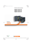
IEC 60870-5-103 communication is available via the ACE969-2 communication
interface.
ACE969-2 is a multiprotocol communication interface with two independent
communication ports:
b The S-LAN (Supervisory-Local Area Network) port is used to connect Sepam to a
communication network dedicated to supervision.
b The E-LAN (Engineering-Local Area Network) port is reserved for specific Sepam
setup, operating and adjustment functions. This port is connected to the SFT2841
software tool.
PB103453
ACE969TP-2 communication interface.
The ACE969-2 interface is available in two versions, linked to the physical interface
of the S-LAN supervision port:
b ACE969TP-2 (Twisted Pair) for an S-LAN network, 2-wire RS 485 serial link
b ACE969FO-2 (Fiber Optic) for a fiber-optic star or ring S-LAN
The E-LAN engineering port is always a 2-wire RS 485 type port.
ACE969FO-2 communication interface.
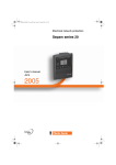
Accessible data
DE81051
1
0
SFT2841
S-LAN
E-LAN
Sepam series 20
ACE969-2
IEC 60870-5-103 communication via the S-LAN port provides access to a great deal
of information, in particular:
b Reading of metering information
b Reading of status conditions and time-tagged events
b Transfer of files including disturbance records and tripping contexts
b Time-setting and synchronization
b Transmission of remote controls
The actual list depends on the application, the type of Sepam, the enabled functions,
and the ACE969-2 interface parameter settings.
Sepam series 40
ACE969-2
Connecting the SFT2841 tool to the E-LAN port also provides access to all Sepam
function parameters and operating data:
b Hardware configuration parameters
b Remote settings for protection functions
b Switching on/off of protection functions
b Retrieval of disturbance records
b Display of metering and diagnosis information
b Display of logic states
b Display of alarms
Sepam series 60/80
ACE969-2
Two independent networks:
S-LAN: IEC 60870-5-103 supervision
E-LAN: For SFT2841 operating functions.
2
SEPED305002EN - 03/2011
IEC 60870-5-103 protocol
IEC 60870-5-103
communication
Selected application functions
of
IEC 60870-5-5
Selected application service
data units of
IEC 60870-5-3
Selected application
information elements of
IEC 60870-5-4
Selected link transmission
procedures of
IEC 60870-5-2
Selected transmission frame
formats of
IEC 60870-5-1
Fiber-optic system based on
IEC 60874-2 or IEC 60874-10
and IEC 60794-1 and IEC
60794-2 or copper-wirebased system according to
EIA RS-485
User process
Application layer
0
Presentation
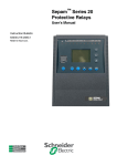
The IEC 60870-5-103 protocol is a companion standard for the informative
interface of protection equipment.
Standard IEC 60870-5-103 was prepared by IEC technical committee 57 (Power
system control and associated communications).
It is a companion standard for the basic standards in series IEC 60870-5.
(Layer 7)
Link layer
(Layer 2)
Physical layer
(Layer 1)
As a companion standard, it adds semantics to the definitions and functional profiles
specified in the basic standards:
b Definition of the particular uses for information objects
b Definition of specialist information objects
b Definition of service procedures or additional parameters in respect of the basic
standards
Standard IEC 60870-5-103 defines communication between protection equipment
and devices of a control system (supervisor or RTU) in a substation.
Standard IEC 60870-5-103 can be obtained in full from the International
Electrotechnical Commission: http://www.iec.ch.
IEC 60870-5-103 communication profile.
SEPED305002EN - 03/2011
3
1
IEC 60870-5-103
communication
IEC 60870-5-103 protocol
0
Protocol principle
1
General
Standard IEC 60870-5-103 defines a multipoint communication protocol via which
information can be exchanged between a control system (supervisor or RTU) and
one or more protection devices. The control system is the master and the protection
devices are the slaves. Each slave is identified by a unique address between 1 and
254. Address 255 is reserved for broadcast frames.
Standard IEC 60870-5-103 defines two different methods for exchanging
information:
b The first is based on the use of predefined data structures (ASDU - Application
Service Data Units) and application procedures supporting the transmission of
standardized information.
b The other uses generic services supporting the transmission of any type of
information.
Sepam does not use generic services.
The protocol distinguishes between:
b The Monitoring direction for the transmission of ASDUs sent by a protection device
(slave device) to the control system (master device).
b The Control direction for ASDUs sent by the control system to a protection device.
Monitoring direction
Communication is based on the cyclic transmission of link-layer polling requests by
the master in order to invite the slave to send its data.
b Class 1 data polling is usually used for event transmission.
b Class 2 data polling is used for the cyclic transmission of metering information.
Control direction
The master can send:
b General commands (enable/disable functions: protection, recloser, etc.)
b A general interrogation request to obtain the current value of slave equipment
status conditions and indications
b A transmission request for disturbance records
b Time synchronization commands
b Commands to reset the communication interface
Communication initialization
The slave communication interface only becomes operational once an initialization
request sent by the master device has been received.
The absence of polling by the master is detected by the slave and this stops
communication. To re-establish communication, the master device must send a
reset request.
Information characteristics
All information exchanged between the control system and the protection equipment
features:
b A function number
b An information number
b The ASDU number used to transmit the information
b The cause of the transmission
4
SEPED305002EN - 03/2011
IEC 60870-5-103
communication
IEC 60870-5-103 protocol
Access to Sepam data
Sepam is a multifunctional digital relay,
which supplies a great deal of information.
Sepam data is categorized on the basis of
function. Compliant with the data model
defined in IEC 60870-5-103, all data is
identified by a function number (FUN) and
an information number (INF).
List of IEC 60870-5-103 standard functions
A detailed description of the Sepam data
table, including function number and
information number, appears in the Sepam
data table section.
0
Sepam supports the subset of standard functions shown below.
Sepam uses the standard FUN and INF numbers for these functions.
FUN
Function name
255
160
1
System
Overcurrent protection
List of Sepam-specific functions
Sepam uses private FUN and INF numbers for these functions.
FUN
Function name
States and indications
20
21
22
31
32
33
41
42
43
Protections
100
101
102
103
104
105
106
107
108
109
Measurements
10
11
12
Sepam supervision
Switchgear and network
Logic equations
Logic inputs (MES no. 1)
Logic inputs (MES no. 2)
Logic inputs (MES no. 3)
Logipam group 1
Logipam group 2
Logipam group 3
Overcurrent protections
Directional current protections
Voltage protections
Frequency protections
Motor/generator protections
Miscellaneous protections
Thermal protections
Power protections
Differential protections
Speed protection
Temperature measurements
Additional measurements 1
Additional measurements 2
List of standard ASDUs
Sepam supports the subset of standard ASDUs shown below.
ASDU Function
1
2
5
6
7
8
9
20
Time-tagged message
Time-tagged message with relative time
Identification message
Time synchronization
General interrogation
End of general interrogation
Measurands II
General command
Monitor
direction
b
b
b
b
Control
direction
b
b
b
b
b
List of private ASDUs
In addition to the functions and standard ASDU, Sepam supports a File transfer
function, which uses private ASDUs.
This function can be used to retrieve:
b Tripping contexts (Sepam series 60, Sepam series 80 only)
b Disturbance records
Disturbance records are supplied in COMTRADE format.
ASDU Function
254
255
SEPED305002EN - 03/2011
Transfer command
Transfer response
Monitoring
direction
Control
direction
b
b
5
1
IEC 60870-5-103
communication
IEC 60870-5-103 protocol
Sepam communication profile
The Sepam communication profile defines
how the options of standard
IEC 60870-5-103 are implemented by
Sepam.
The presentation format and numbering
used in this section are intentionally based
on clause "8. Interoperability" of standard
IEC 60870-5-103.
8. Interoperability
Indicates that Sepam supports the option
from the standard.
Indicates that Sepam does not support
the option.
0
8.1 Physical layer
8.1.1 Electrical interface
EIA RS-485.
Number of loads .......1.............. for one protection device.
Nota : EIA RS-485 standard defines unit loads so that 32 of them can be operated on one line.
For detailed information refer to clause 3 of EIA RS-485 standard.
8.1.2 Optical interface
Glass fiber.
Plastic fiber.
F-SMA type connector.
BFOC/2.5 type connector.
8.1.3 Transmission speed
9,600 bps.
19,200 bps.
8.2 Link layer
There are no choices for the link layer.
8.3 Application layer
8.3.1 Transmission mode for application data
Mode 1 (least significant byte first), as defined in 4.10 of
IEC 60870-5-4, is used exclusively in this companion standard.
8.3.2 COMMON ADDRESS OF ASDU
One COMMON ADDRESS OF ASDU (identical to station address)
More than one COMMON ADDRESS OF ASDU
8.3.3 Selection of standard information numbers in monitoring
direction
8.3.3.1 System functions in monitoring direction
6
INF
<0>
<0>
<2>
<3>
<4>
<5>
Semantics
End of general interrogation
Time synchronization
Reset FCB
Reset CU
Start/restart
Power on
SEPED305002EN - 03/2011
IEC 60870-5-103
communication
IEC 60870-5-103 protocol
Sepam communication profile
0
8.3.3.2 Status indications in monitoring direction
INF
<16>
<17>
<18>
<19>
<20>
<21>
<22>
<23>
<24>
<25>
<26>
<27>
<28>
<29>
<30>
1
Semantics
Auto-recloser active
Teleprotection active
Protection active
LED reset
Monitoring direction blocked
Test mode
Local parameter setting
Characteristic 1
Characteristic 2
Characteristic 3
Characteristic 4
Auxiliary input 1
Auxiliary input 2
Auxiliary input 3
Auxiliary input 4
8.3.3.3 Supervision indications in monitoring direction
INF
<32>
<33>
<35>
<36>
<37>
<38>
<39>
<46>
<47>
Semantics
Measurand supervision I
Measurand supervision V
Phase sequence supervision
Trip circuit supervision
I>> back-up operation
VT fuse failure
Teleprotection disturbed
Group warning
Group alarm
8.3.3.4 Earth fault indications in monitoring direction
SEPED305002EN - 03/2011
INF
<48>
<49>
<50>
<51>
<52>
Semantics
Earth fault L1
Earth fault L2
Earth fault L3
Earth fault forward, i.e. line
Earth fault reverse, i.e. busbar
7
IEC 60870-5-103
communication
IEC 60870-5-103 protocol
Sepam communication profile
0
8.3.3.5 Fault indications in monitoring direction
1
INF
<64>
<65>
<66>
<67>
<68>
<69>
<70>
<71>
<72>
<73>
<74>
<75>
<76>
<77>
<78>
<79>
<80>
<81>
<82>
<83>
<84>
<85>
<86>
<87>
<88>
<89>
<90>
<91>
<92>
<93>
Semantics
Start/pick-up L1
Start/pick-up L2
Start/pick-up L3
Start/pick-up N
General trip
Trip L1
Trip L2
Trip L3
Trip I>> (back-up operation)
Fault location X in ohms
Fault forward/line
Fault reverse/busbar
Teleprotection signal transmitted
Teleprotection signal received
Zone 1
Zone 2
Zone 3
Zone 4
Zone 5
Zone 6
General start/pick-up
Breaker failure
Trip measuring system L1
Trip measuring system L2
Trip measuring system L3
Trip measuring system E
Trip I>
Trip I>>
Trip IN>
Trip IN>>
8.3.3.6 Auto-reclosure indications in monitoring direction
INF
Semantics
<128> CB 'on' by AR
<129> CB 'on' by delayed AR
<130> AR blocked
8.3.3.7 Measurands in monitoring direction
INF
<144>
<145>
<146>
<147>
<148>
Semantics
Measurand
Measurands I, V
Measurands I, V, P, Q
Measurands IN, VEN
Measurands IL1, 2, 3, VL1, 2, 3, P, Q, f
8.3.3.8 Generic functions in monitoring direction
8
INF
<240>
<241>
<243>
<244>
<245>
<249>
<250>
<251>
Semantics
Read headings of all defined groups
Read values or attributes of all entries of one group
Read directory of a single entry
Read value or attribute of a single entry
End of general interrogation of generic data
Write entry with confirmation
Write entry with execution
Write entry aborted
SEPED305002EN - 03/2011
IEC 60870-5-103
communication
IEC 60870-5-103 protocol
Sepam communication profile
0
8.3.4 Selection of standard information numbers in control
direction
1
8.3.4.1 System functions in control direction
INF
<0>
<0>
Semantics
Initiation of general interrogation
Time synchronization
8.3.4.2 General commands in control direction
INF
<16>
<17>
<18>
<19>
<23>
<24>
<25>
<26>
Semantics
Auto-recloser on/off
Teleprotection on/off
Protection on/off
LED reset
Activate characteristic 1
Activate characteristic 2
Activate characteristic 3
Activate characteristic 4
8.3.4.3 Generic functions in control direction
INF
<240>
<241>
<243>
<244>
<245>
<248>
<249>
<250>
<251>
Semantics
Read headings of all defined groups
Read values or attributes of all entries of one group
Read directory of a single entry
Read value or attribute of a single entry
General interrogation of generic data
Write entry
Write entry with confirmation
Write entry with execution
Write entry aborted
8.3.5 Basic application functions
Test mode
Blocking of monitoring direction
Disturbance data
Generic services
Private data
8.3.6 Miscellaneous
Measurands are transmitted with ASDU 3 as well as with ASDU 9. As defined in
7.2.6.8, the maximum MVAL can either be 1.2 or 2.4 times the rated value. No
different rating shall be used in ASDU 3 and ASDU 9, i.e. for each measurand there
is only one choice.
Measurand
Current L1
Current L2
Current L3
Voltage L1-E
Voltage L2-E
Voltage L3-E
Active power P
Reactive power Q
Frequency f
Voltage L1 - L2
SEPED305002EN - 03/2011
Max. MVAL = rated value times
1.2
or
2.4
9
1
IEC 60870-5-103
communication
IEC 60870-5-103 protocol
Sepam data table
All Sepam data that can be exchanged with
a supervisor via the IEC 60870-5-103
protocol is listed in two tables:
b The monitoring direction data table, which
lists all Sepam data to be transmitted to the
supervisor.
b The control direction data table, which
lists all supervisor data to be transmitted to
Sepam.
Description of the Sepam data table
0
The following information is provided for each data item:
b The ASDU (Application Service Data Unit) number
b The value of the FUN (Function) and INF (Information) identifiers
b The value of the COT (Cause Of Transmission) field
b A GI (General Interrogation) marker
b The Sepam data semantic
b The Sepam series for which the data is available
For Sepam series 20, Sepam B2X (dedicated to voltage applications) are distinct
from Sepam S20, T20 and M20 (dedicated to current applications).
The effective availability of a Sepam data item also depends on the Sepam type and
function parameter settings.
ASDU: Application Service Data Unit
The ASDU number identifies the standard data structure used by Sepam for data
transmission.
FUN and INF: Function number and information number
Each Sepam data item is identified by:
b The number of the function to which the data belongs: FUN
b The information number of the basic data: INF
COT: Cause Of Transmission
The COT value shows the cause of transmission of the data.
Monitoring direction
In the monitoring direction, Sepam uses the following COT values:
COT
Label
1
Spontaneous
2
Cyclic
3
Reset (FCB)
4
Reset (CU)
5
Start/restart
8
9
Time synchronization
General interrogation
10
End of general interrogation
12
Remote operation
20
21
Positive acknowledgement
Negative acknowledgement
Information produced spontaneously following a
change of state (date-tagged event)
Information produced cyclically by Sepam
(measurements)
Response to command to reset the frame count bit
(FCB)
Response to command to reset the communication
unit (CU)
Response to command to initialize the
communication interface
Acknowledgment of time synchronization command
Information produced in response to a general
interrogation command
Termination message of a general interrogation
cycle
Change of state resulting from a supervisor
command
Positive acknowledgment of command
Negative acknowledgment of command
Control direction
In the control direction, Sepam supports the following COT values:
COT
Label
8
9
20
Time synchronization
General interrogation
General command
Time synchronization command
Initialization of a general interrogation cycle
Command from the supervisor such as open/close
breaker, enable/disable a function, etc.
GI: General Interrogation
The GI marker indicates whether the data is produced in response to a general
interrogation request. For this data, each change of state ("OFF" to "ON" and "ON"
to "OFF") is also transmitted spontaneously.
10
SEPED305002EN - 03/2011
IEC 60870-5-103 protocol
Sepam data table - Monitoring
direction
IEC 60870-5-103
communication
ASDU FUN INF COT
8
6
5
5
5
255
255
255
255
255
255
System functions
0
10
0
8
2
3
3
4
4
5
ASDU FUN INF COT
160
1
160
1
160
1
160
1
160
1
160
1
1
1
160
160
160
1
160
2
2
2
160
160
160
2
160
2
160
2
160
1
160
GI IEC 60870-5-103 semantic
End of general interrogation
Time synchronization
Reset frame count bit (FCB)
Reset communication unit (CU)
Start/restart
GI IEC 60870-5-103
semantic
Sepam
semantic
Maximum overcurrent protection (IEC 60870-5-103 standard
function)
16
1, 9, 12, b
Auto-recloser active
Recloser on
20, 21
19
1, 12, 20,
LED reset
Sepam reset after
21
fault
20
9, 11
b
Monitoring direction
Monitoring
blocked
direction blocked
23
1, 9, 12, b
Characteristic 1
Setting group A in
20, 21
service
24
1, 9, 12, b
Characteristic 2
Setting group B in
20, 21
service
32
1, 9
b
Measurand supervision I
Phase-CT fault
33
1, 9
b
Measurand supervision V Phase-VT fault
35
1, 9
b
Phase sequence
Main-phase
supervision
reverse rotation
36
1, 9
b
Trip circuit supervision
Matching fault or
Trip Circuit
Supervision
68
1
General trip
Trip
85
1
Breaker failure
Protection 50BF
90
1
Trip I>
Protection 50/51
unit 1
91
1
Trip I>>
Protection 50/51
unit 2
92
1
Trip IN>
Protection 50N/
51N unit 1
93
1
Trip IN>>
Protection 50N/
51N unit 2
128 1
CB 'on' by Auto-recloser
Recloser: reclosing
successful
SEPED305002EN - 03/2011
Sepam series 20 Sepam
series 40
B2X
Other
Sepam
series 60
Sepam
series 80
b
b
b
b
b
b
b
b
b
b
b
b
b
b
b
Sepam
series 60
Sepam
series 80
b
b
b
b
b
b
b
b
b
b
Sepam series 20 Sepam
series 40
B2X
Other
b
b
b
b
b
b
b
b
b
b
b
b
b
b
b
b
b
b
b
b
b
b
b
b
b
b
b
b
b
b
b
b
b
b
b
b
b
b
b
b (unit 1
group A)
b (unit 2
group A)
b (unit 1
group A)
b (unit 2
group A)
b
b
b
b
b
b
b
b
b
b
b
b
b
b
b
b
b
b
b
b
b
b
0
1
11
IEC 60870-5-103
communication
1
ASDU FUN INF COT
20
20
20
20
20
20
20
20
20
20
20
20
20
20
20
1
1
1
1
1
1
1
1
1
1
1
1
1
1
1
1
20
21
21
1
1
1
1
1
1
1
1
1
1
1
1
1
1
1
1
1
1
1
1
1
1
1
1
1
1
1
1
1
1
1
1
1
1
1
1
1
1
1
1
1
1
1
1
1
1
21
21
21
21
21
21
21
21
21
21
21
21
21
21
21
21
21
21
21
21
21
21
21
21
21
21
21
21
21
21
21
21
21
21
21
21
21
21
21
21
21
21
21
21
21
21
12
IEC 60870-5-103 protocol
Sepam data table - Monitoring
direction
GI Sepam semantic
Sepam supervision
1
1, 9
b
Sepam partial fault
2
1, 9
b
Sepam major fault
3
1, 9
b
MET 148-1 module sensor fault
4
1, 9
b
MET 148-2 module sensor fault
5
1, 9
b
Control fault
6
1, 9
b
Residual VT fault
7
1, 9
b
Additional phase CT fault
8
1, 9
b
Additional phase VT fault
9
1, 9
b
Additional residual VT fault
10
1
Min. V_aux
11
1
Max. V_aux
12
1
Battery low or absent
13
1, 9
b
Test mode
14
1, 9, 12, b
S-LAN communication monitoring active
20, 21
15
1
Ethernet communication fault
Switchgear and network
1
1, 9, 12, b
Device closed
20, 21
2
1, 9
b
Device racked out
3
1
SF6 alarm
4
1, 9
b
Earthing switch closed
5
1
Thermistor alarm
6
1
Thermistor tripping
7
1
Buchholz alarm
8
1
Buchholz tripping
9
1
Thermostat alarm
10
1
Thermostat tripping
11
1
Pressure alarm
12
1
Pressure tripping
13
1
External tripping 1
14
1
External tripping 2
15
1
External tripping 3
16
1
Load shedding
17
1
Restart
18
1, 9
b
Additional phase reverse rotation
19
1, 9
b
Recloser ready
20
1
Recloser: final trip
21
1
Send blocking signal 1
22
1
Send blocking signal 2
23
1, 9
b
Closing circuit supervision
24
1
Request for synchro-checked closing
25
1
Synchronization stop
26
1
Synchronization failure
27
1
Synchronization successful
28
1
dU synchronization failure
29
1
dPhi synchronization failure
30
1
dF synchronization failure
31
1
Manual capacitor step control
32
1
Automatic capacitor step control
33
1
Capacitor step 1 matching fault
34
1
Capacitor step 2 matching fault
35
1
Capacitor step 3 matching fault
36
1
Capacitor step 4 matching fault
37
1
Coupling closing order
38
1
Coupling synchronization failure
39
1
Tripping by automatic transfer (AT)
40
1
Cumulative breaking current monitoring
102 20, 21
Ack. of command Priority group shutdown
103 20, 21
Ack. of command Enable/Disable synchro-check
104 20, 21
Ack. of command Enable/Disable voltage check
105 20, 21
Ack. of command Close/Open capacitor step 1
106 20, 21
Ack. of command Close/Open capacitor step 2
107 20, 21
Ack. of command Close/Open capacitor step 3
108 20, 21
Ack. of command Close/Open capacitor step 4
0
Sepam series 20 Sepam
series 40
B2X
Other
Sepam
series 60
Sepam
series 80
b
b
b
b
b
b
b
b
b
b
b
b
b
b
b
b
b
b
b
b
b
b
b
b
b
b
b
b
b
b
b
b
b
b
b
b
b
b
b
b
b
b
b
b
b
b
b
b
b
b
b
b
b
b
b
b
b
b
b
b
b
b
b
b
b
b
b
b
b
b
b
b
b
b
b
b
b
b
b
b
b
b
b
b
b
b
b
b
b
b
b
b
b
b
b
b
b
b
b
b
b
b
b
b
b
b
b
b
b
b
b
b
b
b
b
b
b
b
b
b
b
b
b
b
b
b
b
b
b
b
b
b
b
b
b
b
b
b
b
b
b
b
SEPED305002EN - 03/2011
IEC 60870-5-103 protocol
Sepam data table - Monitoring
direction
IEC 60870-5-103
communication
ASDU FUN INF COT
1
1
1
1
1
1
1
1
1
1
1
1
1
1
1
1
1
1
1
1
1
1
1
1
1
1
1
1
1
1
1
1
1
1
1
1
1
1
1
1
1
1
1
1
1
1
1
1
1
1
1
1
1
1
1
1
22
22
22
22
22
22
22
22
22
22
22
22
22
22
22
22
22
22
22
22
22
22
22
22
22
22
22
22
22
22
22
22
22
22
22
22
22
22
22
22
22
22
22
22
22
22
22
22
22
22
22
22
22
22
22
22
22
GI Sepam semantic
Logic equations
1
1, 9
b
2
1, 9
b
3
1, 9
b
4
1, 9
b
5
1, 9
b
6
1, 9
b
7
1, 9
b
8
1, 9
b
9
1, 9
b
10
1, 9
b
11
1, 9
b
12
1, 9
b
13
1, 9
b
14
1, 9
b
15
1, 9
b
16
1, 9
b
17
1, 9
b
18
1, 9
b
19
1, 9
b
20
1, 9
b
21
1, 9
b
22
1, 9
b
23
1, 9
b
24
1, 9
b
25
1, 9
b
26
1, 9
b
27
1, 9
b
28
1, 9
b
29
1, 9
b
30
1, 9
b
31
1, 9
b
32
1, 9
b
33
1, 9
b
34
1, 9
b
35
1, 9
b
36
1, 9
b
37
1, 9
b
38
1, 9
b
39
1, 9
b
40
1, 9
b
41
1, 9
b
42
1, 9
b
43
1, 9
b
44
1, 9
b
45
1, 9
b
46
1, 9
b
47
1, 9
b
48
1, 9
b
49
1, 9
b
50
1, 9
b
51
1, 9
b
52
1, 9
b
53
1, 9
b
54
1, 9
b
55
1, 9
b
56
1, 9
b
SEPED305002EN - 03/2011
V1
V2
V3
V4
V5
V6
V7
V8
V9
V10
V11
V12
V13
V14
V15
V16
V17
V18
V19
V20
V_FLAGREC
V_TRIPCB
V_CLOSECB
V_INHIBCLOSE
V_RESET
V_CLEAR
V_INHIBIT_RESET_LOCAL
V_SHUTDOWN
V_DE-EXCITATION
V_CLOSE_NOCTRL
V_TRIP_STP1
V_TRIP_STP2
V_TRIP_STP3
V_TRIP_STP4
V_CLOSE_STP1
V_CLOSE_STP2
V_CLOSE_STP3
V_CLOSE_STP4
V_TRANS_ON_FLT
V_TRANS_STOP
V_MIMIC_IN_1
V_MIMIC_IN_2
V_MIMIC_IN_3
V_MIMIC_IN_4
V_MIMIC_IN_5
V_MIMIC_IN_6
V_MIMIC_IN_7
V_MIMIC_IN_8
V_MIMIC_IN_9
V_MIMIC_IN_10
V_MIMIC_IN_11
V_MIMIC_IN_12
V_MIMIC_IN_13
V_MIMIC_IN_14
V_MIMIC_IN_15
V_MIMIC_IN_16
Sepam series 20 Sepam
series 40
B2X
Other
b
b
b
b
b
b
b
b
b
b
b
b
b
b
0
Sepam
series 60
Sepam
series 80
b
b
b
b
b
b
b
b
b
b
b
b
b
b
b
b
b
b
b
b
b
b
b
b
b
b
b
b
b
b
b
b
b
b
b
b
b
b
b
b
b
b
b
b
b
b
b
b
b
b
b
b
b
b
b
b
b
b
b
b
b
b
b
b
b
b
b
b
b
b
b
b
b
b
b
b
b
b
b
b
b
b
b
b
b
b
b
b
b
b
b
b
b
b
b
b
b
b
b
b
b
b
b
b
b
b
b
b
b
b
b
b
13
1
IEC 60870-5-103
communication
1
ASDU FUN INF COT
1
31
31
31
31
31
31
31
31
31
31
31
31
31
31
31
32
32
1
33
3
1
41
41
1
1
1
41
41
41
1
42
42
1
42
1
43
43
1
43
1
1
1
1
1
1
1
1
1
1
1
1
1
1
14
GI Sepam semantic
Logic inputs (MES no. 1)
1
1, 9
b
Logic input
2
1, 9
b
Logic input
3
1, 9
b
Logic input
4
1, 9
b
Logic input
5
1, 9
b
Logic input
6
1, 9
b
Logic input
7
1, 9
b
Logic input
8
1, 9
b
Logic input
9
1, 9
b
Logic input
10
1, 9
b
Logic input
11
1, 9
b
Logic input
12
1, 9
b
Logic input
13
1, 9
b
Logic input
14
1, 9
b
Logic input
Logic inputs (MES no. 2)
1 to 1, 9
b
Logic inputs I201 to I214
14
Logic inputs (MES no. 3)
1 to 1, 9
b
Logic inputs I301 to I314
14
Logipam group 1 (Sepam series 80 option)
16 to 1, 9
b
TS16 to TS31
31
106 20, 21
Ack. of command TC6
107 20, 21
Ack. of command TC7
110 20, 21
Ack. of command TC10
to
to
Ack. of command TC17
117
Logipam group 2 (Sepam series 80 option)
33 to 1, 9
b
TS33 to TS48
48
121 20, 21
Ack. of command TC21
to
to
129
Ack. of command TC29
Logipam group 3 (Sepam series 80 option)
52 to 1, 9
b
TS52 to TS64
64
149 20, 21
Ack. of command TC49
to
to
Ack. of command TC64
164
IEC 60870-5-103 protocol
Sepam data table - Monitoring
direction
0
Sepam series 20 Sepam
series 40
B2X
Other
Sepam
series 60
Sepam
series 80
I11
I12
I13
I14
I21
I22
I23
I24
I25
I26
I101
I102
I103
I104
I105
I106
I107
I108
I109
I110
I111
I112
I113
I114
I101
I102
I103
I104
I105
I106
I107
I108
I109
I110
I111
I112
I113
I114
b
b
I11
I12
I13
I14
I21
I22
I23
I24
I25
I26
I11
I12
I13
I14
I21
I22
I23
I24
I25
I26
b
b
b
b
b
b
b
b
b
SEPED305002EN - 03/2011
IEC 60870-5-103 protocol
Sepam data table - Monitoring
direction
IEC 60870-5-103
communication
ASDU FUN INF COT
GI Sepam semantic
2
100
100
Overcurrent protections
1
1
Protection 50/51 unit 3
2
100
2
1
Protection 50/51 unit 4
2
2
2
2
2
100
100
100
100
100
3
4
5
6
7
1
1
1
1
1
Protection 50/51 unit 5
Protection 50/51 unit 6
Protection 50/51 unit 7
Protection 50/51 unit 8
Protection 50N/51N unit 3
2
100
8
1
Protection 50N/51N unit 4
2
2
2
2
2
2
100
100
100
100
100
100
101
101
101
101
101
102
102
102
102
102
102
102
102
102
102
102
102
102
102
102
102
102
102
9
1
Protection 50N/51N unit 5
10
1
Protection 50N/51N unit 6
11
1
Protection 50N/51N unit 7
12
1
Protection 50N/51N unit 8
13
1
Protection 51V unit 1
14
1
Protection 51V unit 2
Directional current protections
1
1
Protection 67 unit 1
2
1
Protection 67 unit 2
3
1
Protection 67N unit 1
4
1
Protection 67N unit 2
Voltage protections
1
1
Protection 27/27S unit 1
2
1
Protection 27/27S unit 2
3
1
Protection 27/27S unit 3
4
1
Protection 27/27S unit 4
5
1
Protection 27D unit 1
6
1
Protection 27D unit 2
7
1
Protection 27R unit 1
8
1
Protection 27R unit 2
11
1
Protection 59 unit 1
12
1
Protection 59 unit 2
13
1
Protection 59 unit 3
14
1
Protection 59 unit 4
21
1
Protection 59N unit 1
22
1
Protection 59N unit 2
31
1
Protection 27S phase 1
32
1
Protection 27S phase 2
33
1
Protection 27S phase 3
2
2
2
2
2
2
2
2
2
2
2
2
2
2
2
2
2
2
2
2
2
SEPED305002EN - 03/2011
Sepam series 20 Sepam
Sepam
series 40 series 60
B2X
Other
b (unit 1
group B)
b (unit 2
group B)
b (unit 1
group B)
b (unit 2
group B)
0
Sepam
series 80
b
b
b
b
b
b
b
b
b
b
b
b
b
b
b
b
b
b
b
b
b
b
b
b
b
b
b
b
b
b
b
b
b
b
b
b
b
b
b
b
b
b
b
b
b
b
b
b
b
b
b
b
b
b
b
b
b
b
b
b
b
b
b
b
b
b
b
b
b
b
b
b
b
b
b
b
b
b
b
b
b
15
1
IEC 60870-5-103
communication
1
ASDU FUN INF COT
103
103
103
103
103
103
103
103
103
104
104
104
104
104
104
104
104
104
104
104
104
104
105
105
105
105
105
105
105
105
105
105
105
105
105
105
105
105
2
2
2
2
2
2
2
2
2
2
2
1
2
2
2
2
2
2
2
2
2
2
2
2
2
2
2
2
2
2
2
2
2
2
1
16
IEC 60870-5-103 protocol
Sepam data table - Monitoring
direction
GI Sepam semantic
Frequency protections
1
1
Protection 81H unit 1
2
1
Protection 81H unit 2
11
1
Protection 81L unit 1
12
1
Protection 81L unit 2
13
1
Protection 81L unit 3
14
1
Protection 81L unit 4
21
1
Protection 81R unit 1
22
1
Protection 81R unit 2
Motor/generator protections
1
1
Protection 48/51LR (locked rotor)
2
1
Protection 48/51LR (locked rotor at start-up)
3
1
Protection 48/51LR (excessive starting time)
4
1, 9
b
Protection 66
5
1
Protection 21B
6
1
Protection 50/27
7
1
Protection 64G2/27TN unit 1
8
1
Protection 64G2/27TN unit 2
9
1
Protection 78PS
10
1
Protection 24 unit 1
11
1
Protection 24 unit 2
12
1
Protection 40
Miscellaneous protections
1
1
Protection 46 unit 1
2
1
Protection 46 unit 2
3
1
Protection 46BC
11
1
Protection 47 unit 1
12
1
Protection 47 unit 2
20
1
Protection 37
31
1
Protection 51C unit 1 (capacitor step 1)
32
1
Protection 51C unit 2 (capacitor step 1)
33
1
Protection 51C unit 3 (capacitor step 2)
34
1
Protection 51C unit 4 (capacitor step 2)
35
1
Protection 51C unit 5 (capacitor step 3)
36
1
Protection 51C unit 6 (capacitor step 3)
37
1
Protection 51C unit 7 (capacitor step 4)
38
1
Protection 51C unit 8 (capacitor step 4)
101 20, 21
Ack. of command Reset undercurrent protection
0
Sepam series 20 Sepam
series 40
B2X
Other
Sepam
series 60
Sepam
series 80
b
b
b
b
b
b
b
b
b
b
b
b
b
b
b
b
b
b
b
b
b
b
b
b
b
b
b
b
b
b
b
b
b
b
b
b
b
b
b
b
b
b
b
b
b
b
b
b
b
b
b
b
b
b
b
b
b
b
b
b
b
b
b
b
b
b
b
b
b
b
b
b
b
b
b
b
b
b
b
SEPED305002EN - 03/2011
IEC 60870-5-103
communication
ASDU FUN INF COT
1
1
1
1
1
1
1
1
1
1
1
1
1
1
1
1
1
1
1
1
1
1
1
1
1
1
1
1
1
1
1
1
1
1
1
2
2
2
2
2
2
2
2
2
1
1
1
1
106
106
106
106
106
106
106
106
106
106
106
106
106
106
106
106
106
106
106
106
106
106
106
106
106
106
106
106
106
106
106
106
106
106
106
106
107
107
107
107
107
107
108
108
108
108
108
109
109
109
109
109
IEC 60870-5-103 protocol
Sepam data table - Monitoring
direction
GI Sepam semantic
Thermal protections
1
1
Protection 49 RMS alarm set point
2
1
Protection 49 RMS tripping set point
3
1, 9, 12, b
Thermal protection tripping inhibited
20, 21
11
1
Protection 38/49T tripping sensor 1 module 1
12
1
Protection 38/49T tripping sensor 2 module 1
13
1
Protection 38/49T tripping sensor 3 module 1
14
1
Protection 38/49T tripping sensor 4 module 1
15
1
Protection 38/49T tripping sensor 5 module 1
16
1
Protection 38/49T tripping sensor 6 module 1
17
1
Protection 38/49T tripping sensor 7 module 1
18
1
Protection 38/49T tripping sensor 8 module 1
21
1
Protection 38/49T tripping sensor 1 module 2
22
1
Protection 38/49T tripping sensor 2 module 2
23
1
Protection 38/49T tripping sensor 3 module 2
24
1
Protection 38/49T tripping sensor 4 module 2
25
1
Protection 38/49T tripping sensor 5 module 2
26
1
Protection 38/49T tripping sensor 6 module 2
27
1
Protection 38/49T tripping sensor 7 module 2
28
1
Protection 38/49T tripping sensor 8 module 2
31
1
Protection 38/49T alarm sensor 1 module 1
32
1
Protection 38/49T alarm sensor 2 module 1
33
1
Protection 38/49T alarm sensor 3 module 1
34
1
Protection 38/49T alarm sensor 4 module 1
35
1
Protection 38/49T alarm sensor 5 module 1
36
1
Protection 38/49T alarm sensor 6 module 1
37
1
Protection 38/49T alarm sensor 7 module 1
38
1
Protection 38/49T alarm sensor 8 module 1
41
1
Protection 38/49T alarm sensor 1 module 2
42
1
Protection 38/49T alarm sensor 2 module 2
43
1
Protection 38/49T alarm sensor 3 module 2
44
1
Protection 38/49T alarm sensor 4 module 2
45
1
Protection 38/49T alarm sensor 5 module 2
46
1
Protection 38/49T alarm sensor 6 module 2
47
1
Protection 38/49T alarm sensor 7 module 2
48
1
Protection 38/49T alarm sensor 8 module 2
Power protections
1
1
Protection 32P unit 1
2
1
Protection 32P unit 2
3
1
Protection 32Q
11
1
Protection 37P unit 1
12
1
Protection 37P unit 2
Differential protections
1
1
Protection 64REF unit 1
2
1
Protection 64REF unit 2
10
1
Protection 87T2
11
1
Protection 87M/87G
Speed protections
1
1
Protection 12 unit 1
2
1
Protection 12 unit 2
3
1
Protection 14 unit 1
4
1
Protection 14 unit 2
SEPED305002EN - 03/2011
Sepam series 20 Sepam
series 40
B2X
Other
0
Sepam
series 60
Sepam
series 80
b
b
b
b
b
b
b
b
b
b
b
b
b
b
b
b
b
b
b
b
b
b
b
b
b
b
b
b
b
b
b
b
b
b
b
b
b
b
b
b
b
b
b
b
b
b
b
b
b
b
b
b
b
b
b
b
b
b
b
b
b
b
b
b
b
b
b
b
b
b
b
b
b
b
b
b
b
b
b
b
b
b
b
b
b
b
b
b
b
b
b
b
b
b
b
b
b
b
b
b
b
b
b
b
b
b
b
b
b
b
b
b
b
b
b
b
b
b
b
b
b
b
b
b
b
b
b
b
b
b
b
b
b
b
b
b
b
b
b
b
b
b
b
b
b
b
b
b
b
b
17
1
IEC 60870-5-103
communication
1
ASDU FUN INF COT
160
160
9
10
10
9
11
11
9
IEC 60870-5-103 protocol
Sepam data table - Monitoring
direction
GI Sepam semantic
Standard measurements
148 2
9 information elements MEA1 to MEA9
MEA1: Phase current I1
MEA2: Phase current I2
MEA3: Phase current I3
MEA4: Phase-to-neutral voltage V1
MEA5: Phase-to-neutral voltage V2
MEA6: Phase-to-neutral voltage V3
MEA7: Active power P
MEA8: Reactive power Q
MEA9: Frequency f
Temperature measurements
1
2
16 information elements: 16 temperatures MEA1 to
MEA16, as a % of full scale (i.e. 200°C)
MEA1: Temperature sensor 1 module 1
MEA2: Temperature sensor 2 module 1
MEA3: Temperature sensor 3 module 1
MEA4: Temperature sensor 4 module 1
MEA5: Temperature sensor 5 module 1
MEA6: Temperature sensor 6 module 1
MEA7: Temperature sensor 7 module 1
MEA8: Temperature sensor 8 module 1
MEA9: Temperature sensor 1 module 2
MEA10: Temperature sensor 2 module 2
MEA11: Temperature sensor 3 module 2
MEA12: Temperature sensor 4 module 2
MEA13: Temperature sensor 5 module 2
MEA14: Temperature sensor 6 module 2
MEA15: Temperature sensor 7 module 2
MEA16: Temperature sensor 8 module 2
Additional measurements 1
1
2
13 information elements MEA1 to MEA13
MEA1: Residual current I0Σ
Sepam series 20 Sepam
series 40
B2X
Other
12
12
9
18
MEA3: Negative sequence / unbalance T
MEA4: Phase-to-phase voltage U21
MEA5: Phase-to-phase voltage U32
MEA6: Phase-to-phase voltage U13
MEA7: Residual voltage V0
MEA8: Positive sequence voltage Vd
MEA9: Negative-sequence voltage Vi
MEA10: Power factor Cos Phi
MEA11: Neutral-point voltage Vnt
MEA12: Total harmonic distortion Uthd
MEA13: Total harmonic distortion Ithd
Additional measurements 2
1
2
16 information elements MEA1 to MEA16
MEA1: Phase current I’1
MEA2: Phase current I’2
MEA3: Phase current I’3
MEA4: Residual current I’0Σ
MEA5: Residual current I’0
MEA6: Phase-to-phase voltage U’21
MEA7: Phase-to-phase voltage U’32
MEA8: Phase-to-phase voltage U’13
MEA9: Phase-to-neutral voltage V’1
MEA10: Phase-to-neutral voltage V’2
MEA11: Phase-to-neutral voltage V’3
MEA12: Residual voltage V’0
MEA13: Positive sequence voltage V’d
MEA14: Negative-sequence voltage V’i
MEA15: Frequency f’
MEA16: Negative sequence / unbalance T’
Sepam
series 80
b
b
b
b
b
b
b
b
b
b
b
b
b
b
b
b
b
b
b
b
b
b
b
b
b
b
b
b
b
b
b
b
b
b
b
b
b
b
b
b
b
b
b
b
b
b
b
b
b
b
b
b
b
b
b
b
b
b
b
b
b
b
b
b
b
b
b
b
b
b
b
b
b
b
b
b
b
b
b
b
b
b
b
b (I0Σ
or I0)
b (I0Σ
or I0)
b
b
b
b
b
b
b
b
b
b
b
b
b
b
b
b
b
b
b
b
b
b
b
b
b
b
b
b
b
b
b
b
b
b
b
b
b
b
b
b
b
b
b
Sepam
series 60
b
b
b
b
b
b
MEA2: Residual current I0
0
b
b
b
b
b
b
b
b
b
b
b
b
b
b
b
b
SEPED305002EN - 03/2011
IEC 60870-5-103
communication
ASDU FUN INF COT
7
6
20
20
20
20
20
255
255
255
160
160
20
160
160
160
20
20
20
21
21
20
21
20
21
20
21
20
21
20
21
20
21
20
21
20
20
105
106
20
20
20
41
41
41
41
20
42
42
20
43
43
IEC 60870-5-103 protocol
Sepam data table - Control direction
GI Sepam semantic
System functions
0
9
Initiation of general interrogation
0
8
Time synchronization
General commands
16
20
Enable recloser (ON)
Disable recloser (OFF)
19
20
Sepam reset (ON)
23
20
Switching to setting group A (ON)
24
20
Switching to setting group B (ON)
Sepam monitoring
14
20
S-LAN communication monitoring (re)activation (ON)
S-LAN communication monitoring inhibition (OFF)
Switchgear and network commands
1
20
Closing (ON)
Trip/open (OFF)
102 20
Priority group shutdown (ON)
Cancel priority group shutdown (OFF)
103 20
Enable synchro-check (ON)
Disable synchro-check (OFF)
104 20
Enable voltage check (ON)
Disable voltage check (OFF)
105 20
Close capacitor step 1 (ON)
Open capacitor step 1 (OFF)
106 20
Close capacitor step 2 (ON)
Open capacitor step 2 (OFF)
107 20
Close capacitor step 3 (ON)
Open capacitor step 3 (OFF)
108 20
Close capacitor step 4 (ON)
Open capacitor step 4 (OFF)
Other commands
101 20
Reset undercurrent protection (ON)
3
20
Inhibit thermal protection (ON)
Confirm thermal protection (OFF)
Logipam group 1 (Sepam series 80 option) TC available for the user
106 20
TC6
107 20
TC7
110 20
TC10 to TC17
to
117
Logipam group 2 (Sepam series 80 option) TC available for the user
121 20
TC21 to TC29
to
129
Logipam group 3 (Sepam series 80 option) TC available for the user
149 20
TC49 to TC64
to
164
SEPED305002EN - 03/2011
Sepam series 20 Sepam
series 40
B2X
Other
Sepam
series 60
Sepam
series 80
b
b
b
b
b
b
b
b
b
b
b
b
b
b
b
b
b
b
b
b
b
b
b
b
b
b
b
b
b
b
b
b
b
b
b
b
b
b
b
b
b
b
b
b
b
b
b
b
b
b
b
b
b
b
b
b
b
19
0
1
IEC 60870-5-103
communication
Configuring the communication
interfaces
0
Presentation
The Sepam communication interfaces must be configured using SFT2841 software.
1
The IEC 60870-5-103 protocol is available with the ACE969TP-2 or ACE969FO-2
communication interfaces.
Several parameter categories have to be configured once the interface has been
selected:
b The configuration parameters for the physical layer of the E-LAN port
b The configuration parameters for the physical layer of the S-LAN port
b The configuration parameters for functions specific to the
IEC 60870-5-103 protocol (advanced S-LAN port parameters)
PE80012
Access to configuration parameters
These parameters can be accessed from the Communication configuration
window in the SFT2841 software.
To access this window:
b Display the Sepam configuration screen in SFT2841. This screen will vary
according to the type of Sepam used.
b Select the Communication option.
b Click
: the Communication configuration window appears.
b Select the type of interface used (ACE969TP-2 or ACE969FO-2).
b Select the IEC103 communication protocol (S-LAN port).
SFT2841: Sepam series 80 hardware configuration.
PE80013
Configuration of the E-LAN port
Configuration of the physical layer
The E-LAN port on the ACE969TP-2 and ACE969FO-2 communication interfaces is
a 2-wire RS 485 port.
The configuration parameters for the physical layer of the E-LAN port are:
b Sepam address
b Transmission speed
b Parity check type
Parameters
Authorized values
Default value
Sepam address
1 to 247
1
Speed
4800, 9600, 19200 or
38400 bps
No parity, Even or
Odd
38400 bps
Parity
Configuration of the physical layer of the E-LAN port
on an ACE969TP.
20
Odd
Configuration tips
b The Sepam address MUST be assigned before Sepam is connected to the E-LAN
communication network.
b You are also strongly advised to set the other physical layer configuration
parameters before connecting to the communication network.
b Modifying the configuration parameters during normal operation will not disturb
Sepam but will reset the E-LAN communication port. If SFT2841 is connected to
Sepam via the E-LAN network, any communication between Sepam and SFT2841
will be interrupted.
SEPED305002EN - 03/2011
IEC 60870-5-103
communication
Configuring the communication
interfaces
0
PE80013
Configuration of the S-LAN port:
Physical layer
The configuration parameters will vary depending on the communication interface
selected: ACE969TP or ACE969FO.
ACE969TP: 2-wire RS 485 S-LAN port
The configuration parameters for the physical layer of the S-LAN port on the
ACE969TP are:
b Sepam address
b Transmission speed
b Parity check type
Parameters
Authorized values
Default value
Sepam address
Speed
0 to 254
4800, 9600, 19200 or
38400 bps
No parity, Even or Odd
1
19200 bps
Parity
Even
Configuration of the physical layer of the S-LAN port
on an ACE969TP.
PE80014
ACE969FO: Fiber-optic S-LAN port
The configuration parameters for the physical layer of the S-LAN port on the
ACE969FO-2 are:
b Sepam address
b Transmission speed
b Parity check type
b Link idle state: Light On or Light Off
b Echo mode: Yes or No
Echo mode must be activated when the Sepam is connected to an optical ring
communication network.
Parameters
Authorized values
Default value
Sepam address
Speed
0 to 254
4800, 9600, 19200 or
38400 bps
No parity, Even or Odd
Light Off or
Light On
Yes (optical ring) or
No (optical star)
1
19200 bps
Parity
Link idle state
Echo mode
Configuration of the physical layer of the S-LAN port
on an ACE969FO.
SEPED305002EN - 03/2011
Even
Light Off
No
Configuration tips
b The Sepam address MUST be assigned before Sepam is connected to the S-LAN
communication network.
b You are also strongly advised to set the other physical layer configuration
parameters before connecting to the communication network.
b Modifying the configuration parameters during normal operation will not disturb
Sepam but will reset the S-LAN communication port.
21
1
IEC 60870-5-103
communication
Configuring the communication
interfaces
0
Configuration of the S-LAN port:
IEC 60870-5-103 protocol
1
Configuration of the IEC 60870-5-103 protocol functions
The configuration of the IEC 60870-5-103 protocol functions is identical whether the
ACE969TP-2 interface or the ACE969FO-2 interface is used.
Click the Advanced parameters button in the ACE969-2 configuration windows to
open the IEC 103 Protocol parameters window, in which the following can be
configured:
b The standard parameters as defined by standard IEC 60870-5-103
b The Sepam private data to be exchanged with the supervisor
Configuration of the standard parameters
PE80015
The standard IEC 60870-5-103 protocol parameters are as follows:
b Cyclic ASDU period
b Inactivity timer
b Time synchronization period
b Blocking of monitoring direction
Cyclic ASDU period
Period during which cyclic data, such as measurement information, is generated and
updated by Sepam.
This parameter, which is expressed in seconds, must be set consistently with the
interval at which this data is polled by the supervisor.
Inactivity timer
In normal operation, the supervisor sends polling requests to the Sepam units at
regular intervals. Each Sepam monitors the activity of the supervisor by checking that
polling requests are being received regularly.
If a Sepam fails to receive requests during a configurable period (the inactivity time
delay), it will lock its communication port and cease to respond to requests sent
subsequently by the supervisor.
To re-establish communication with a locked Sepam, the supervisor must initiate a
reset.
Configuration of the IEC 60870-5-103 protocol.
Time synchronization period
Time synchronization is transmitted via ASDU 6.
If this ASDU has not been received at the end of time T (time synchronization period),
Sepam will assume that its clock setting may be inaccurate and will assign the
information "Invalid time" to time-tagged data.
Blocking of monitoring direction
Sepam can suspend the transmission of data in the monitoring direction, in
accordance with the procedure specified by IEC 60870-5-103.
22
Parameters
Authorized values
Default value
Cyclic ASDU period
Inactivity timer
Time synchronization period
Blocking of monitoring direction
0 to 60 seconds
0 to 60000 seconds
0 to 60000 minutes
No or Yes
10 seconds
0 (infinite)
0
No
SEPED305002EN - 03/2011
IEC 60870-5-103
communication
Configuring the communication
interfaces
0
Selection of the data to be exchanged
Sepam private data is categorized in three subsets:
b States and indications
b Protections
b Measurements
In each subset, the data is organized into functional groups. A functional group is
identified by a function number (FUN).
The data groups to be exchanged with the supervisor can be selected in the
configuration window.
Only the data groups required for the application should be selected, in order to avoid
overloading communication unnecessarily (in particular in the event of a general
interrogation on the part of the supervisor).
PE80015
FUN Function
20
21
22
31
32
33
41
42
43
100
101
102
103
104
105
Configuration of the IEC 60870-5-103 protocol.
SEPED305002EN - 03/2011
States and indications
Sepam supervision
Switchgear and network
Logic equations
Logic inputs (MES no. 1)
Logic inputs (MES no. 2)
Logic inputs (MES no. 3)
Logipam (group 1)
Logipam (group 2)
Logipam (group 3)
Protections
Overcurrent protections
Directional
current protections
Voltage protections
Frequency protections
Motor/generator protections
Miscellaneous protections
Sepam series 20 Sepam Sepam
Sepam
B2X
Other
series 40 series 60 series 80
b
NA
NA
v
NA
NA
NA
NA
NA
b
b
NA
v
NA
NA
NA
NA
NA
b
b
v
v
NA
NA
NA
NA
NA
b
b
v
v
v
NA
NA
NA
NA
b
b
v
v
v
v
v
v
v
NA
NA
b
NA
b
b
b
b
b
b
b
b
NA
NA
NA
NA
b
b
b
b
b
b
b
b
b
b
b
b
b
b
Thermal protections
NA
b
b
b
b
Power protections
NA
NA
b
b
b
Differential protections
NA
NA
NA
b
b
Speed protections
NA
NA
NA
b
b
Measurements
10
Temperature measurements NA
v
v
v
v
11
Additional measurements 1 b
b
b
b
b
12
Additional measurements 2 NA
NA
NA
NA
v
b Function available and selected by default
v Function available and not selected by default
NA (Not Applicable): Function not available for a Sepam series, not displayed in the IEC103
Protocol parameters window
106
107
108
109
23
1
IEC 60870-5-103
communication
DANGER
1
HAZARD OF ELECTRIC SHOCK, ELECTRIC
ARC OR BURNS
b Only qualified personnel should install this
equipement. Such work should be performed only
after reading this entire set of instrucions and
checking the technical characteristics of the
device.
b NEVER work alone.
b Turn off all power supplying this equipement
before working on or inside it. Consider all
sources of power, including the possibility of
backfeeding.
b Always use a properly rated voltage sensing
device to confirm that all power is off.
b Start by connecting the device to the protective
earth and to the functional earth.
b Screw tight all terminals, even those not in use.
Failure to follow these instructions will result
in death or serious injury.
Commissioning and diagnosis
0
Installation and operating instructions for
Sepam
The communication interfaces must be installed and connected in accordance with
the instructions in each Sepam user’s and operation manual.
b Sepam series 20 user’s manual, reference PCRED301005EN,
b Sepam series 40 user’s manual, reference PCRED301006EN,
b Sepam series 60 user’s manual, reference PCRED310017EN,
b Sepam series 80 operation manual, reference SEPED303003EN,
Preliminary checks
The following preliminary checks must be made:
b Check the CCA612 cord connection between the ACE969-2 interface and the
Sepam base unit.
b Check the auxiliary power supply connection to the ACE969-2.
b Check the connection between the S-LAN communication port and the ACE969-2.
b Check the complete configuration of the ACE969-2.
Checking the operation of the ACE969-2
interface
You can use the following to check that the ACE969-2 interface is operating
correctly:
b The indicator LEDs on the front panel of the ACE969-2
b The information provided by the SFT2841 software connected to Sepam:
v On the Diagnosis screen
v On the Communication configuration screens
PB103454
Indicator LEDs on the ACE969-2
b Green "on" LED: ACE969-2 energized
b Red "key" LED: ACE969-2 interface status
v LED off: ACE969-2 configured and communication operational
v LED flashing: ACE969-2 configuration error or ACE969-2 not configured
v LED on: ACE969-2 error
b S-LAN and E-LAN Tx / Rx LEDs:
v S-LAN Tx LED flashing: Sepam transmitting
v S-LAN Rx LED flashing: Sepam receiving
v Tx and Rx off: RS 485 communication is idle
v Tx or Rx LED is "on" while the RS 485 communication network is idle: the idle
voltage state of the RS 485 network is incorrect
ACE969TP-2 communication interface.
PE80016
Diagnosis using SFT2841 software
Sepam diagnosis screen
When connected to Sepam, the SFT2841 software informs the operator of the
general Sepam status and of the Sepam communication status in particular.
All Sepam status information appears on the Sepam diagnosis screen.
SFT2841: Sepam series 80 diagnosis screen.
24
Sepam communication diagnosis
The operator is provided with the following information to assist with identifying and
resolving communication problems:
b Name of the protocol configured
b IEC 60870-5-103 interface version number
b Number of frames received
b Number of mistaken frames received
These two counters are reset to zero if:
b The maximum value (65535) is reached
b The Sepam auxiliary power supply is lost
b The communication parameters are modified
SEPED305002EN - 03/2011
IEC 60870-5-103
communication
Commissioning and diagnosis
0
Troubleshooting assistance
The following diagnosis information indicates whether Sepam and a supervisor are
communicating correctly using the IEC 60870-5-103 protocol:
b Indicator LEDs on the front panel of the ACE969-2:
v Green "on" LED on
v Red "key" LED off
v S-LAN Rx and Tx LEDs flashing
b Sepam diagnosis screen:
v Name of the protocol configured: IEC 60870-5-103
v IEC 60870-5-103 interface version number displayed
v Number of frames received increasing at regular intervals
v Number of mistaken frames received not increasing
Deviations from the above indicate that communication between Sepam and the
supervisor has failed. The table below lists the possible causes of communication
failures, along with the associated course of action to be taken in each case.
Symptoms
ACE969-2 LEDs
"On" LED off
"Key" LED on
"Key" LED flashing
S-LAN Rx LED flashing
SFT2841 diagnosis
Protocol = ????
and/or Version = ????
Protocol = ????
and/or Version = ????
Protocol = ????
and/or Version = ????
Increase in mistaken frame
counter value
Possible cause
Action/Remedy
No power supply to ACE969-2
Check the auxiliary power supply to the
ACE969-2.
Replace the ACE969-2.
ACE969-2 failed
ACE969-2 not configured
ACE969-2 is not connected to Sepam.
The ACE969-2 configuration is incorrect.
The ACE969-2 physical layer configuration is
incorrect.
Configure the ACE969-2 using SFT2841.
Check the ACE969-2 connection to Sepam.
Use SFT2841 to check the interface selected:
ACE969TP-2 or ACE969FO-2.
Use SFT2841 to check the following
parameters:
b Transmission speed
b Parity
Check the communication protocol selected.
The communication protocol selected is
incorrect.
The S-LAN network is not properly connected. Check the connection of the S-LAN network and
the RS 485 remote power supply.
S-LAN Rx LED flashing
The frame counter values are The supervisor is not sending frames to Sepam. Use SFT2841 to check the Sepam address
not increasing.
parameter and check that the supervisor is
sending frames to Sepam.
The communication protocol selected is
Check the communication protocol selected.
incorrect.
S-LAN Rx LED off
The supervisor is not sending frames on the
Check that the supervisor is operating correctly.
network.
The S-LAN network is not properly connected. Check the connection of the S-LAN network and
the RS 485 remote power supply.
Tx or Rx LED is "on" while the
The idle voltage state of the RS 485 network b Check that the pull-up and pull-down bias
resistors are correctly installed on the RS 485
is incorrect.
RS 485 communication network
is idle.
network.
b Check that the 2 load resistors are correctly
installed at each end of the RS 485 network.
SEPED305002EN - 03/2011
25
1
IEC 60870-5-103
communication
Appendix 1: Sepam data coding
0
Presentation
The Monitoring and Control data managed by Sepam is coded in accordance with
the structure of standard ASDUs as specified in standard IEC 60870-5-103.
1
ASDU
COT
Monitoring
direction
1
1
1
9
b
b
2
5
9
20
1
3,4,5
2
20
b
b
b
Control
direction
b
Description
Changes of state
States in response to general
interrogation
Protection equipment tripping indication
Identification
Measurements
Commands
Status information coding:
ASDU 1 and ASDU 2
Information on Sepam states and indications is coded using ASDU 1 and ASDU 2.
It is obtained via requests to scan class 1 data.
ASDU 1
Bytes
1
2
3
4
5
6
7
8
9
10
11
12
1
81h
1 or 9
@
FUN
INF
DPI
Time-tagged
label
Description
ASDU number
Structure qualifier
COT: 1 (spontaneous) or 9 (General Interrog. resp.)
ASDU common address: Sepam address
FUN: function number
INF: information number
DPI (Double Point Information): 1=OFF - 2=ON
Milliseconds (least significant byte)
Milliseconds (most significant byte)
Minutes + invalidity bit (most significant bit)
Hours + Summer time bit (most significant bit)
Additional information: 0 if COT=1
General interrogation number if COT=9
ASDU 2
Bytes
1
2
3
4
5
6
7
8
9
10
11
12
13
14
15
16
26
2
81h
1
@
FUN
INF
DPI
0
0
0
0
Time-tagged
label
Description
ASDU number
Structure qualifier
COT: 1 (spontaneous)
ASDU common address: Sepam address
FUN: function number
INF: information number
DPI (Double Point Information): 1=OFF - 2=ON
REL: Relative time elapsed between appearance
of the fault and tripping (not managed by Sepam)
FAN: Fault number (not managed by Sepam)
Milliseconds (least significant byte)
Milliseconds (most significant byte)
Minutes + invalidity bit (most significant bit)
Minutes + Summer time bit (most significant bit)
Additional information: 0 if COT=1
General interrogation number if COT=9
SEPED305002EN - 03/2011
IEC 60870-5-103
communication
Appendix 1: Sepam data coding
0
Sepam identification: ASDU 5
ASDU 5 is generated by Sepam in response to initialization commands sent by the
master:
b Reset CU (Communication Unit)
b Reset FCB (Frame Count Bit)
IEC 60870-5-103 communication is only operational after initialization by the master
station. In response to this initialization request, Sepam generates two successive
ASDU 5 type messages.
ASDU 5 in response to Reset CU
First ASDU 5 message:
Second ASDU 5 message:
COT = 4 (Reset CU) and INF = 3
COT = 5 (Start/restart) and INF = 4
ASDU 5 in response to Reset FCB
First ASDU 5 message:
Second ASDU 5 message:
COT = 3 (Reset FCB) and INF = 2
COT = 5 (Start/restart) and INF = 4
Once communication has been established, if the master sends a new initialization
request, only the first ASDU 5 message is generated.
ASDU 5
Bytes
1
2
3
4
5
6
7
8
9
10
11
12
13
14
15
16
17
18
19
SEPED305002EN - 03/2011
5
81h
COT
@
FUN
INF
2
"S"
"E"
""
"S"
"E"
"P"
"A"
"M"
"G"
"4"
"0"
""
Description
ASDU number
Structure qualifier
COT: 3, 4 or 5
ASDU common address: Sepam address
FUN: function number
INF: information number 2, 3 or 4
Compatibility level
(level 2: Sepam does not support IEC 60870-5103 generic services)
Manufacturer identification (8 ASCII characters)
"SE SEPAM"
Application software identification (4 ASCII
characters)
For example, "G40 " for Sepam series 40
Generator application
27
1
IEC 60870-5-103
communication
Appendix 1: Sepam data coding
0
Measurement coding: ASDU 9
Sepam measurements are coded using ASDU 9.
They are obtained via requests to scan class 2 data.
1
The size of ASDU 9 depends on the number of measurements provided.
The number of measurements is shown in the Structure qualifier field.
ASDU 9
Bytes
1
2
3
4
5
6
7
8
..
..
..
Zz
Description
ASDU number
Number of measurements coded in ASDU
COT: 2 (cyclical)
ASDU common address: Sepam address
FUN: function number
INF: information number
Measurement 1 (least significant byte)
Measurement 1 (most significant byte)
9
n
2
@
FUN
INF
MES 1
...
..
MES n
Measurement n (least significant byte)
Measurement n (most significant byte)
Where Zz = 8 + 2 x (n - 1)
Each measurement is coded on 2 bytes.
The value provided is a value standardized by IEC 60870-5-103 which is coded as a
13-bit 2's complement value (bits 3 to 15). It is expressed in relation to a reference
value.
Bit 0 is the overflow bit (OV: Overflow)
Bit 1 is the error bit (ERR)
Bit 2 is a reserved bit (RES); it is always 0
15
14
Most significant byte
Least significant byte
13
12
11
10
9
8
7
6
5
4
3
2
1
0
Signed IEC standardized value on 13 bits
RES ERR OV
The actual value measured by Sepam is obtained from the IEC standardized value
using the following formula:
S tan dardized value CEI + 1
Measured value = Reference value × -----------------------------------------------------------------------
2 12
Sepam provides different types of measurements for which the reference values are:
Measurement types Reference value
Dynamic
Currents
Voltages
Powers (P, Q)
Frequencies
Negative sequence/
unbalance, total harmonic
distortion, etc.
Cos Phi
Temperature
1.2 x Rated current
1.2 x Rated voltage
1.2 x U x I x 3
1.2 x Rated frequency
1.2
120%
120%
120%
120%
120%
1
200°C
100%
100%
For example, if the rated current on Sepam is set to 630 A, the current value coded
as 3251 represents a measured current equal to 600 A.
The value 3251 (0CB3h) is coded:
0
0
28
1
Most significant byte
Least significant byte
Signed IEC standardized value on 13 bits
RES ERR
1
0
0
1
0
1
1
0
0
1
1
0
0
C
B
3
0
0
OV
0
0
SEPED305002EN - 03/2011
IEC 60870-5-103
communication
Appendix 1: Sepam data coding
0
Command coding: ASDU 20
1
Commands are sent to Sepam (enable/disable functions, open/close, remote
controls, etc.) via ASDU 20.
A command is always confirmed by Sepam through generation of an
acknowledgement message by return using ASDU 1 (COT 20).
The General Command ASDU includes an identification number (Return Information
Identifier, from 0 to 255), selected arbitrarily by the master. This number is copied as
is by Sepam into the Command Acknowledgement ASDU so that a link can be
established with the Command ASDU.
The value of the command is coded in the DCI (Double Command Information) byte;
the authorized values are OFF (1) and ON (2).
ASDU 20
Bytes
1
2
3
4
5
6
7
8
SEPED305002EN - 03/2011
20
81h
20
@
FUN
INF
DCI
RII
Description
ASDU number
Structure qualifier
COT: 20 (general command)
ASDU common address: Sepam address
FUN: function number
INF: information number
DCI (Double Command Information): 1=OFF - 2=ON
RII: Return Information Identifier
29
IEC 60870-5-103
communication
Appendix 2: File transfer
General
0
Presentation
Sepam records information, in the form of files, produced by the following functions:
b Disturbance records
b Tripping contexts (for Sepam series 60 and Sepam series 80 only)
These files can be retrieved using a file transfer procedure based on private ASDUs
254 and 255.
1
Types of file to be transferred
Definitions
The files that can be transferred from Sepam to the supervisor are:
b 1 DR (Disturbance Records) directory file, which contains the information required
for transferring disturbance record files saved in Sepam
b 1 TR (Tripping Records) directory file, which contains the information required for
transferring Tripping context files saved in Sepam
b Disturbance record files, which contain data saved in Sepam on events via the
Disturbance recording function
b Tripping context files, which contain data saved by Sepam on tripping
File names
Each file is identified by a name coded in ASCII-character.
File
File name
Size of file name (in bytes)
DR directory
Disturbance records
TR directory
Tripping contexts
DR
yyyy-mm-dd-hh-mn-sssss
TR
yyyy-mm-dd-hh-mn-sssss
2
22
2
22
The name of Disturbance record and Tripping context files is encoded with the date
the file is saved by Sepam:
b yyyy: year coded on 4 ASCII characters
b mm: month coded on 2 ASCII characters, from 01 to 12
b dd: day coded on 2 ASCII characters, from 01 to 31
b hh: hour coded on 2 ASCII characters, from 00 to 23
b mn: minutes coded on 2 ASCII characters, from 00 to 59
b sssss: milliseconds coded on 5 ASCII characters, from 00000 to 59999
Transfer principle
A Disturbance record file is transferred from Sepam to the supervisor in three stages:
1. The DR directory file is read by the supervisor
2. The contents of the DR file is interpreted by the supervisor, to identify the
Disturbance record file to be transferred
3. The selected Disturbance record file is read
A Tripping context file is transferred from Sepam to the supervisor in the same way,
using the TR directory file.
30
SEPED305002EN - 03/2011
IEC 60870-5-103
communication
Appendix 2: File transfer
General
0
Reading a file
Procedure
The same procedure applies for reading all files (directory files and data files).
This consists of an exchange of requests/responses between the supervisor and
Sepam:
b The supervisor sends requests based on ASDU 254 (private ASDU).
b Responses from Sepam are retrieved by the supervisor via requests to scan class
1 data. Responses from Sepam are based on ASDU 255 (private ASDU).
A file is read in three stages:
1. The file to be transferred is opened via an Open request/response
2. Data is transferred from the file through a succession of Read Block requests/
responses
3. The file is closed via a Close request/response
Notes
b Only one file can be open at any one time: the directory must therefore be closed
after reading, in order to be able to read one of the files in this directory.
b For an open file, only one transfer is permitted at any one time.
b A data block contains a maximum of 238 bytes. The number of Read Block
requests necessary to transfer a file depends on its size.
ASDU requests and responses
SEPED305002EN - 03/2011
ASDU FUN
Control
direction
254
255
254
255
255
254
255
b
105
105
101
101
103
106
106
Monitoring
direction
b
b
b
b
b
b
Description
Open request
Open response
Read Block request
Read Block positive response
Read Block negative response
Close request
Close response
31
1
IEC 60870-5-103
communication
Appendix 2: File transfer
General
0
Checking and processing errors
Sepam performs a series of checks to ensure that a file is read correctly.
Any error that occurs whilst a file is being read causes the file to be closed
automatically by Sepam.
1
Block number sequence check
Data blocks are numbered starting at 0. Blocks must be read in ascending order.
It is possible to reread the same block i several times, as long as no request has been
made for the next block i+1 to be read.
A sequence error in the block number requested in a Read Block request generates
a negative Read Block response (status = incorrect block number).
Data integrity check
A Disturbance record file or Tripping context file in Sepam can be overwritten at any
time by a new record if a new event occurs. If a file is in the process of being read,
then data obtained by the supervisor will be corrupt. Sepam signals this error in the
Close response (status = corrupt file).
Inactivity check: aborting a read operation
Sepam manages an inactivity time delay when a file read operation has been
initialized, and throughout the entire course of the read operation. If there is more
than 60 seconds between two Read Block requests or between the last Read Block
request and the Close request, Sepam automatically closes the file. A spontaneous
Close response is generated by Sepam (status = file closed on detection of
inactivity).
Execution reports
Responses from Sepam contain an execution report coded in the Status field of
ASDU 255.
The values possible in the Status field are listed in the table below:
Status
Description
0
3
5
6
OK
Open error response: file does not exist
Open error response: file already open
Read Block negative response and Close error response: file
identifier incorrect
Read Block negative response and Close error response: file not
open
Spontaneous Close response: file closed on detection of inactivity
Close error response: file corrupted
Read Block negative response: block number incorrect
16
17
19
20
32
SEPED305002EN - 03/2011
IEC 60870-5-103
communication
Appendix 2: File transfer
ASDU coding
0
Presentation
ASDU 254 and 255 are used to perform the 3 steps necessary for reading a file:
b Open the file
b Read the data blocks
b Close the file
Coding of the request from the supervisor (ASDU 254) and coding of the response
from Sepam (ASDU 255) is given for each step.
Opening a file
Open request
Field
Size
(bytes)
1
1
1
1
n
Description
Description
255
105
X
Status
Least significant
Size
(bytes)
1
1
1
1
4
Most significant
Least significant
4
File size in bytes
(value on 32 bits)
254
105
X
n
Byte 1
...
Byte n
ASDU number
FUN function number
Request number, selected arbitrarily by the supervisor
Length of the file name to be opened
Name of the file to be opened
Open response
Field
ASDU number
FUN function number
Number of the corresponding Open req.
Execution report
File identifier
This identifier must be used in Read Block and Close
requests
Most significant
SEPED305002EN - 03/2011
33
1
IEC 60870-5-103
communication
Appendix 2: File transfer
ASDU coding
0
Reading a data block
1
Read Block request
Field
254
101
Size
(bytes)
1
1
4
4
Description
ASDU number
FUN function number
Open file identifier (provided by Sepam in the Open
response)
Block number to be read
Read Block positive response
Field
255
101
n
Byte 1
...
Byte n
Size
(bytes)
1
1
4
Description
4
Block number read (most-significant bit at 1 if last
block)
Block size in bytes
Block data
1
n
ASDU number
FUN function number
Open file identifier
For the last block, the most significant bit in the Block number field is set to 1 by
Sepam.
Read Block negative response
Field
255
103
Status
Size
(bytes)
1
1
4
Description
1
Error report
Size
(bytes)
1
1
1
4
Description
Size
(bytes)
1
1
1
4
Description
ASDU number
FUN function number
Open file identifier
Closing a file
Close request
Field
254
106
X
ASDU number
FUN function number
Request number, selected arbitrarily by the supervisor
Open file identifier (provided by Sepam in the Open
response)
Close response
Field
255
106
X
Status
34
1
ASDU number
FUN function number
Number of the corresponding Close req.
Open file identifier (provided by Sepam in the Open
response)
Execution report
SEPED305002EN - 03/2011
Appendix 2: File transfer
Frame sequences exchanged in
order to read a file
IEC 60870-5-103
communication
0
DE80245
Example 1: Complete read operation with no
errors
Control system
Application
layer
Protection equipment
IEC103 link
layer
IEC103 link
layer
Application
layer
SEND
ASDU 254
FUN 105
Start reading:
Open file
Open request
CONFIRM
Scan class 1
data
REQUEST
CLASS 1
RESPOND
ASDU 255
FUN 105
Open
response
SEND
ASDU 254
FUN 101
Read first block
Read Block (0) req.
CONFIRM
Scan class 1
data
REQUEST
CLASS 1
RESPOND
ASDU 255
FUN 101
Read Block
response
SEND
ASDU 254
FUN 101
Read block
Read Block (1) req.
CONFIRM
Scan class 1
data
REQUEST
CLASS 1
RESPOND
ASDU 255
FUN 101
...
Read last block
Read Block (n) req.
...
...
Read Block (1)
response
...
SEND
ASDU 254
FUN 101
CONFIRM
Scan class 1
data
REQUEST
CLASS 1
RESPOND
ASDU 255
FUN 101
Close file
Close request
Read Block (n)
response
(last block)
SEND
ASDU 254
FUN 106
CONFIRM
Scan class 1
data
REQUEST
CLASS 1
RESPOND
ASDU 255
FUN 105
Close
response
End of file reading
SEPED305002EN - 03/2011
35
1
Appendix 2: File transfer
Frame sequences exchanged in
order to read a file
IEC 60870-5-103
communication
0
Example 2: Read operation interrupted on
error (Read Block negative response)
DE80246
1
Control system
Application
layer
Protection equipment
IEC103 link
layer
Start reading:
Open file
Open request
IEC103 link
layer
Application
layer
SEND
ASDU 254
FUN 105
CONFIRM
Scan class 1
data
REQUEST
CLASS 1
RESPOND
ASDU 255
FUN 105
...
...
...
...
...
Open
response
...
SEND
ASDU 254
FUN 101
Read block
Read Block (i) req.
CONFIRM
REQUEST
CLASS 1
Scan class 1
data
RESPOND
ASDU 255
FUN 103
Termination of reading
on error
Read
Block (i)
negative
response
If an error occurs on a Read Block request, Sepam returns a negative Read Block
response. The open file is automatically closed by Sepam.
DE80247
Example 3: Read operation interrupted on
Sepam abort (spontaneous Close response)
Control system
Protection equipment
Application
layer
IEC103 link
layer
IEC103 link
layer
Application
layer
...
...
...
...
...
...
...
...
SEND
ASDU 254
FUN 101
Read block
Read Block (i) req.
...
Delay > 60 seconds
...
Read block
Read Block (i+1) req.
...
...
...
SEND
ASDU 254
FUN 101
CONFIRM
Scan class 1
data
Termination of reading
on abort
REQUEST
CLASS 1
RESPOND
ASDU 255
FUN 103
Spontaneaous
Close
response
If more than 60 seconds elapses between two Read Block requests or between the
last Read Block request and the Close request, Sepam automatically closes the file.
A spontaneous Close response is generated by Sepam (status = file closed on
detection of inactivity).
36
SEPED305002EN - 03/2011
IEC 60870-5-103
communication
Appendix 2: File transfer
Use of files by the supervisor
0
DR or TR directory files
1
A directory file is a list of file descriptors.
DE80335
Directory file
File 1 descriptor
File 2 descriptor
File x descriptor
Least significant
...
Most significant
Least significant
File x descriptor
4
File size in bytes
(32-bit value)
1
Length of file name
22
File name (22 ASCII characters)
yyyy-mm-dd-hh-mn-sssss
Most significant
16H (22)
...
Size
Description
(bytes)
2
File type:
1= Single file
XXh (byte 1)
...
XXh (byte 22)
File n descriptor
Disturbance record file
DR\yyyy-mm-dd-hh-mn-sssss
Disturbance records produced by Sepam are coded in COMTRADE format. This
format is also the one used in the IEC 60870-5-103 standard (only the file reading
procedure is different from the one defined by IEC 60870-5-103).
A COMTRADE disturbance record consists of two standard files:
b A .CFG file, which includes the record configuration parameters (definition of
analog and digital channels recorded, definition of sampling characteristics)
b A .DAT file, which includes the sampled values recorded for each channel
The disturbance record files are stored in Sepam in the directory DR. The name of
each file gives the date and time of its production. It is coded
yyyy-mm-dd-hh-mn-sssss
A disturbance record file produced by Sepam is structured in such a way that the
COMTRADE.CFG and .DAT files can be easily obtained.
Structure of a Sepam disturbance record file
Low byte
High byte
Size
Description
(bytes)
2
Size in bytes (n) of the .CFG configuration data zone
(16-bit value)
n
Configuration parameters
(.CFG file, ASCII format)
X
Samples values
(.DAT file, binary format)
.CFG zone
.DAT zone
SEPED305002EN - 03/2011
37
Appendix 2: File transfer
Use of files by the supervisor
IEC 60870-5-103
communication
0
Tripping context files
TR\yyyy-mm-dd-hh-mn-sssss
1
The tripping context files are stored in Sepam in the directory TR. The name of each
file gives the date and time of its production. It is coded
yyyy-mm-dd-hh-mn-sssss
A tripping context file contains a set of measurements recorded by Sepam when a
protection function trips.
It consists of two parts:
b Date of the context, coded on 8 bytes
b List of measurements, with each measurement coded on 32 bits (4 bytes)
Structure of a Sepam tripping context file
Date
Measurement 1
...
...
...
...
Measurement 44
Size
(bytes)
8
Description
4
List of 44 measurements
Each measurement is a 32-bit numeric value coded
on 4 bytes, from the most significant to the least
significant.
Context date
...
4
The tripping context date is coded on 8 bytes
7
1
2
3
4
5
6
7
8
38
0
0
0
0
6
5
4
3
Reserved
Year
0
2
1
0
0
Month
0
0
Day
0
0
Hours
0
Minutes
Milliseconds (most significant)
Milliseconds (least significant)
0
Reserved value, always 0
Year from 0 to 99
Month from 1 to 12
Day from 1 to 31
Hours from 0 to 24
Minutes from 0 to 59
Milliseconds from 0 to 59999
SEPED305002EN - 03/2011
IEC 60870-5-103
communication
Appendix 2: File transfer
Use of files by the supervisor
0
The tripping context comprises the 44 measurements listed in the table below.
No.
Information
Format
Unit
1
2
3
4
5
6
7
8
9
10
11
12
13
14
15
16
17
18
19
20
21
22
23
24
25
26
27
28
29
30
31
32
33
34
35
36
37
38
39
40
41
42
43
44
Tripping current phase 1 Itrip1
Tripping current phase 2 Itrip2
Tripping current phase 3 Itrip3
Residual current I0Σ
Residual current I0
Negative-sequence current Ii
Phase-to-phase voltage U21
Phase-to-phase voltage U32
Phase-to-phase voltage U13
Phase-to-neutral voltage V1
Phase-to-neutral voltage V2
Phase-to-neutral voltage V3
Residual voltage V0
Positive sequence voltage Vd
Negative-sequence voltage Vi
Frequency f
Active power P
Reactive power Q
Apparent power S
Additional tripping current I’trip1
Additional tripping current I’trip2
Additional tripping current I’trip3
Additional residual current I’0Σ
Additional residual current I’0
Additional negative-sequence current I’i
Phase-to-phase voltage U’21
Phase-to-phase voltage U’32
Phase-to-phase voltage U’13
Phase-to-neutral voltage V’1
Phase-to-neutral voltage V’2
Phase-to-neutral voltage V’3
Residual voltage V’0
Positive sequence voltage V’d
Negative-sequence voltage V’i
Frequency f’
Neutral-point voltage Vnt
H3 neutral-point voltage V3nt
H3 residual voltage V3r
Differential current Id1
Differential current Id2
Differential current Id3
Through current It1
Through current It2
Through current It3
32NS
32NS
32NS
32NS
32NS
32NS
32NS
32NS
32NS
32NS
32NS
32NS
32NS
32NS
32NS
32NS
32S
32S
32S
32NS
32NS
32NS
32NS
32NS
32NS
32NS
32NS
32NS
32NS
32NS
32NS
32NS
32NS
32NS
32NS
32NS
32NS
32NS
32NS
32NS
32NS
32NS
32NS
32NS
0.1 A
0.1 A
0.1 A
0.1 A
0.1 A
0.1 A
1V
1V
1V
1V
1V
1V
1V
1V
1V
0.01 Hz
1 kW
1 kvar
1 kVA
0.1 A
0.1 A
0.1 A
0.1 A
0.1 A
0.1 A
1V
1V
1V
1V
1V
1V
1V
1V
1V
0.01 Hz
1V
0.1%
0.1%
0.1 A
0.1 A
0.1 A
0.1 A
0.1 A
0.1 A
1
The tripping context measurements are 32-bit numeric values coded on 4 bytes, from
the most significant to the least significant.
The following formats are used:
b 32 NS: 32-bit non-signed value
b 32 S: 32-bit signed 2's complement value
SEPED305002EN - 03/2011
39
1
40
SEPED305002EN - 03/2011
ART.805763 © 2011 Schneider Electric - All rights reserved
Schneider Electric Industries SAS
35, rue Joseph Monier
CS 30323
F - 92506 Rueil-Malmaison Cedex
RCS Nanterre 954 503 439
Share capital 896 313 776 €
www.schneider-electric.com
SEPED305002EN/6
As standards, specifications and designs change from time to time, please ask for confirmation
of the information given in this publication.
Printed on recycled paper.
Production: Assystem France
Publication: Schneider Electric
Printed:
03/2011