1
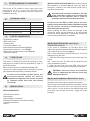
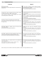
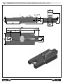
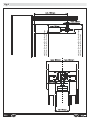
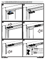
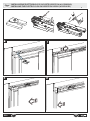
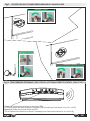
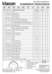
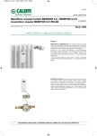
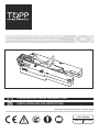
ELETTROBLOCCO PER PORTE A SCOMPARSA ELECTRIC LOCK FOR SLIDE-AWAY DOORS IT ISTRUZIONI PER L’INSTALLAZIONE E L’USO EN INSTALLATION AND USE INSTRUCTIONS EB1 ISTRUZIONI ORIGINALI/ORIGINAL INSTRUCTIONS COD. 0P5466 VER 0.0 REV 02.15 1 DICHIARAZIONE “CE” DI CONFORMITÀ L’apparecchio è certificato ‘CE’ in quanto facente parte degli accessori dell’attuatore V1 e V1E (Vedi par. 6 del relativo manuale istruzioni per l’installazione e l’uso ). 2 DATI TECNICI MODELLO EB1 TENSIONE DI ALIMENTAZIONE 24 V POTENZA 5W GRADO DI PROTEZIONE TEMPERATURA DI FUNZIONAMENTO 3 IPX0 -5°C ÷ +50°C TIPOLOGIA DI UTILIZZO L’apparecchio è stato progettato per bloccare l’apertura dell’anta su porte scorrevoli a scomparsa da interno automatizzate con attuatore Topp V1 e V1E. Dimensioni minime utili per l’installazione ( vedi fig 1-2). L’apparecchio è inoltre dotato di sblocco d’emergenza( manuale e a filo ) incluso nella confezione. Per l’utilizzo dell’EB1 nei locali pubblici è indispensabile installare il kit sblocco di emergenza a filo ad un’altezza accessibile anche a persone disabili e con limitate capacità motorie. 5 Prima di procedere all’installazione dell’EB1 predisporre il passaggio del cavo di collegamento e dell’eventuale cavo del kit sblocco a filo, se necessario richiedere l’intervento di un esperto per la posa in opera. INDICAZIONE DEI COMPONENTI La confezione contiene: n. 1 Elettroblocco EB1; n. 1 Vite di fissaggio; n. 1 Cavo di collegamento L=5mt; n. 2 Kit Sbocco manuale a manopola (Fig. 5); n. 1 Kit Sblocco a filo L=1,5mt (Fig.6); n. 1 Etichetta per il telecomando opzionale (Fig.10); n. 1 Manuale istruzioni. 4 AVVERTENZE PER L’INSTALLAZIONE: Dopo aver verificato la possibilità di installazione (par. 4), definire anche la tipologia di sblocco d’emergenza da utilizzare (kit sblocco manuale o kit sblocco a filo). E’ necessario che venga installato un kit sblocco dal lato dell’automazione ed uno dal lato opposto per garantire l’accesso in sicurezza da entrambe le direzioni. Per l’utilizzo dell’EB1 nei locali pubblici è indispensabile installare il kit sblocco di emergenza a filo ad un’altezza accessibile anche a persone disabili e con limitate capacità motorie. INSTALLAZIONE ACCESSORI NECESSARI: n.1 trapano con punta da 10mm; n.1 spellafili; n.1 tronchese o seghetto da acciaio; n.1 seghetto con lama per plastica (per kit sblocco manuale); n.1 cacciavite a stella; n.1 matita. 2 INSTALLAZIONE ELETTROBLOCCO (Fig.3) Proseguire quindi con l’installazione dell’ EB1 come descritto in seguito : In caso di installazione su porte tipo Doortech, sostituire preventivamente la staffa di ancoraggio con l’apposita staffa (da richiedere come accessorio) (fig.4). a-b : Sollevare la staffa di aggancio e inserirla nel carrello di scorrimento dell’anta; c : Far scorrere l’EB1 sul binario fino ad incontrare il carrello dell’anta; d-e : Portare l’anta in chiusura, l’EB1 verrà trascinato fino a raggiungere la corretta posizione di installazione; f : Aprire l’anta e fissare l’EB1 con la vite in dotazione senza spostarlo dalla posizione raggiunta. ATTENZIONE: Prestare cautela alla forza applicata, in quanto un serraggio eccessivo della vite potrebbe danneggiare l’apparato. INSTALLAZIONE KIT SBLOCCO MANUALE (Fig.5): Per l’installazione del kit sblocco di emergenza manuale procedere come di seguito indicato: Dopo aver verificato la possibilità di installazione, trovare la posizione esatta e forare lo stipite con il trapano utilizzando una punta da 10mm. Tagliare gli alberini alla lunghezza definita e inserirli nell’EB1 come indicato. Applicare quindi le manopole in dotazione. INSTALLAZIONE KIT SBLOCCO A FILO (Fig.6): Per l’installazione del kit sblocco di emergenza a filo è necessario togliere l’EB1 dalla sua posizione, segnare quindi con una matita l’esatto punto di installazione dell’EB1. Procedere quindi come di seguito indicato: Inserire la guaina all’interno della struttura della porta e farla fuoriuscire tramite in foro d.10mm praticato ad un’altezza da terra pari a max 80cm (vedi par.5 IT EB1 avvertenze per l’installazione). Se necessario richiedere l’intervento di un esperto per la posa in opera. Attenzione: la guaina non è predisposta per essere piegata con un raggio inferiore a 30mm. Tagliare la guaina facendo attenzione che agli estremi rimanga il foro per l’inserimento del cavo in acciaio. Inserire il terminale del cavo in acciaio nell’apposita sede dell’EB1 (dettaglio A) e fissarlo con le due viti indicate. Riposizionare e fissare definitivamente l’EB1 nella corretta ubicazione. Infilare il cavo in acciaio all’interno della guaina fino a farlo fuoriuscire all’estremità opposta. Spingere la guaina fino a ricoprire perfettamente il cavo. Infilare l’estremità del cavo in acciaio all’interno del supporto pulsante (dettaglio B) e fissarlo nella posizione prevista avvitando le due viti. Inserire il fermacavo metallico (dettaglio C) all’interno del supporto in plastica e infilare il cavo in acciaio. Fissarlo lasciando 1mm di gioco. Per assicurarsi che il cavo sia fissato correttamente, provare ad attivare l’EB1 e sbloccarlo tirando il coperchietto. Tagliare il cavo in linea con il supporto in plastica utilizzando un tronchesino o un seghetto per acciaio. Applicare il pulsante a pressione (dettaglio D). 6 COLLEGAMENTO ELETTRICO (Fig.7) To g l i e r e i l c a v o d i a l i m e n t a z i o n e dall’automazione prima di effettuare il collegamento elettrico. Solo per l’automazione V1: Posizionare il dip-switch n°7 in posizione ON. Collegare il cavo dell’EB1 alla scheda dell’automazione tramite il connettore A . Collegare anche il relativo pulsante a sfioramento HS2 (vedi relativo manuale di installazione ed uso) o altro pulsante utilizzando il morsetto B indicato in figura. Per il corretto utilizzo dei morsetti dell’automazione V1 e V1E vedere anche il relativo manuale per l’installazione e l’ uso fig.22. 7 PROCEDURA DI INIZIALIZZAZIONE O RESET Una volta effettuato il collegamento elettrico e comunque in caso di errore, è necessario far eseguire all’automazione una procedura di inizializzazione. Se il collegamento è stato eseguito correttamente, l’automazione farà compiere all’EB1 una manovra di blocco e una di sblocco oltre all’apprendimento indicato nel manuale per l’installazione e l’uso V1 e V1E par. 4.2. 8 FUNZIONAMENTO Per attivare l’EB1 e quindi bloccare l’anta in chiusura utilizzare il pulsante a sfioramento HS2 o altro pulsante (per il collegamento vedi Fig.7 morsetto B). Per il corretto utilizzo dei morsetti dell’automazione V1 e V1E vedere anche il relativo manuale per l’installazione e l’ uso fig.22. Per disattivare l’EB1 e quindi sbloccare l’anta sfiorare nuovamente il pulsante a sfioramento HS2 o ripremere il pulsante relativo; la porta apre e si richiude senza bloccarsi. NOTE: è necessario attendere 3 secondi tra un comando di apertura/chiusura ed il successivo; se dopo la richiesta di attivazione dell’EB1 il sensore dall’altro lato viene stimolato, la chiamata rimane attiva per 15 secondi per poi disattivarsi; è necessario quindi liberare il sensore e premere nuovamente il pulsante di attivazione dell’EB1. FUNZIONE BLOCCO PORTA APERTA/PULIZIA: Tenere attivo il pulsante a sfioramento HS2 o altro pulsante per almeno 8 secondi. La porta si apre e la spia luminosa (se installata) diventa lampeggiante. Per ripristinare l’automazione, ripetere l’operazione. La porta si chiude e riprende le funzionalità impostate. 9 SPIA LUMINOSA OPZIONALE Per segnalare l’attivazione dell’EB1 è necessario collegare una spia luminosa seguendo le istruzioni della figura 8. La spia accesa fissa segnala l’attivazione del EB1 e quindi il blocco dell’anta in chiusura. La spia lampeggiante segnala la funzione ‘blocco porta aperta/pulizia’. 10 TELECOMANDO OPZIONALE E’ possibile comandare l’EB1 anche tramite telecomando fornito da Topp (solo con V1). Applicare al telecomando l’etichetta contenuta nella confezione. Per le funzioni vedi fig. 10. EB1 IT 3 11 MANOVRE DI EMERGENZA In caso di mancanza di tensione di rete o di malfunzionamento è possibile sbloccare manualmente l’EB1 tramite il kit sblocco di emergenza manuale o a filo precedentemente installato. La porta rimane libera ed è possibile aprirla manualmente. Vedi fig. 9. 12 MANUTENZIONE L’ e l e t t r o b l o c c o E B 1 n o n n e c e s s i t a d i manutenzione, in caso in cui si presentassero anomalie di funzionamento, contattare il servizio di assistenza tecnica Topp spa. 13 DEMOLIZIONE La demolizione dell’unità EB1 deve avvenire nel rispetto della legislazione vigente in materia di tutela ambientale. E’ quindi obbligatorio procedere alla differenziazione delle parti che costituiscono l’unità di alimentazione secondo le diverse tipologie di materiale. 4 IT EB1 14 PROBLEMI E LORO RIMEDI PROBLEMA RIMEDIO L’EB1 non funziona (la spia luminosa opzionale rileva il comando e rimane fissa) Se l’anta è bloccata utilizzare lo sblocco manuale; scollegare l’automazione e controllare il corretto collegamento. Eseguire la procedura di inizializzazione. Dopo il comando di chiusura l’anta tenta la chiusura e dopo 4 tentativi l’EB1 si disattiva (la spia luminosa opzionale rileva il comando di chiusura ma poi si spegne) Controllare la presenza di un ostacolo nell’anta ed eventualmente rimuoverlo; controllare che dal lato opposto il sensore di rilevamento sia libero. Nota: Dopo 30 sec dal comando l’EB1 si disattiva (e la spia opzionale si spegne). Effettuare la procedura di inizializazzione. Dato il comando di chiusura l’anta rimane libera (la spia luminosa opzionale rileva il comando ma poi si spegne ) Controllare la presenza di un ostacolo nel perno di chiusura dell’EB1 ed eventualmente rimuoverlo; scollegare l’alimentazione dell’automazione e controllarne il corretto collegamento elettrico. Effettuare la procedura di inizializzazione. Dato il comando di riapertura l’anta non si sblocca (la spia luminosa opzionale rimane accesa fissa) Aprire l’anta con l’apposito sblocco manuale; scollegare l’alimentazione e controllarne il corretto collegamento elettrico. Eseguire la procedura di inizializzazione. L’EB1 esegue correttamente l’apertura e la chiusura ma l’anta non si muove (la spia luminosa opzionale si accende per rilevare il comando) Scollegare l’alimentazione e controllarne il corretto collegamento elettrico. Eseguire la procedura di inizializzazione. Dato il comando di apertura/chiusura l’EB1 non risponde (la spia luminosa opzionale rimane spenta). L’automazione esegue un reset. Scollegare l’alimentazione e controllarne il corretto collegamento elettrico. Eseguire la procedura di inizializzazione. In caso non si riesca a risolvere il problema contattare il centro di assistenza Topp. EB1 IT 5 1 EC DECLARATION OF CONFORMITY This device is EC certified in that it forms part of the accessories for the V1 and V1E actuators (See paragraph 6 of the associated instruction manual for installation and use). 2 TECHNICAL DATA MODEL EB1 VOLTAGE SUPPLY 24 V POWER 5W PROTECTION CLASS OPERATING TEMPERATURE 3 IPX0 -5°C ÷ +50°C LIST OF COMPONENTS The package contains: 1 EB1 electric lock; 1 fastening bolt; 1 connection cable L = 5m; 2 knob-based manual release kits (Fig. 5); 1 wire-based release kit L = 1.5m (Fig.6); 1 label for the optional remote control (Fig.10); 1 instruction manual. 4 TYPE OF USE This device is designed to block the opening of slideaway doors for interiors that are automated by Topp V1 and V1E actuators. Minimum dimensions for installation (see fig. 1-2). The device is also equipped with an emergency release (wire-based manual release), included in the box. In order to use the EB1 in public spaces, the wire-based manual release kit must be installed at a height that can also be accessed by disabled people and those with limited movement. 5 INSTALLATION TOOLS NECESSARY: INSTALLATION PRECAUTIONS:After having checked that installation is possible (par. 4), select the type of emergency release to be used (manual release kit or wire-based release kit). One release kit should be installed on the side of the automation system and one should be installed on the opposite side in order to guarantee safe access from both directions. In order to use the EB1 in public spaces, the wirebased manual release kit must be installed at a height that can also be accessed by disabled people and those with limited movement. Before installing the EB1, prepare the passage of the connection cable and the passage of the wire-based release kit where applicable. If necessary request the services of a professional for installation. INSTALLING THE ELECTRIC LOCK (Fig.3) Install the EB1 as follows: In the event of installation on Doortech doors, first replace the anchoring bracket with the dedicated bracket (to be ordered as an accessory) (fig.4). a-b : Lift the attachment bracket and insert it into the sliding trolley for the door; c : Slide the EB1 along the track until it meets the door trolley; d-e : Close the door. The EB1 will be pulled into the correct installation position; f : Open the door and secure the EB1 using the bolt provided, without moving it from the position it reached. WARNING: Take care not to use excessive force as tightening the bolt too much may damage the device. INSTALLING THE MANUAL RELEASE KIT (Fig.5): Install the manual emergency release kit as follows: After having checked that installation is possible, find the exact position and drill a hole in the door jamb using a 10mm drill bit. Cut the shafts to the defined length and insert them into the EB1 as shown. Apply the knobs provided. 1 drill with 10mm drill bit; 1 wire stripper; 1 pair of clippers or hacksaw; 1 hacksaw for plastic (for manual release kit); 1 cross-tip screwdriver; 1 pencil. 6 EN EB1 INSTALLING THE WIRE-BASED RELEASE KIT (Fig.6): In order to install the wire-based emergency release kit, the EB1 must be removed from its position. Mark the exact installation position of the EB1 with a pencil before removal. Proceed as follows: Insert the sheath inside the structure of the door and make it come out through a 10mm hole drilled at a maximum height of 80cm above ground level (see par.5, installation precautions). If necessary request the services of a professional for installation. Attention: the sheath is not designed to be bent by a radius of less than 30mm. Cut the sheath, taking care to leave a hole at each end for the insertion of the steel cable. Insert the end of the steel cable into the dedicated housing on the EB1 (detail A) and secure it with the two screws shown. Reposition the EB1 and secure it definitively in the correct location. Slide the steel cable into the sheath until it comes out of the other end. Push the sheath so that it covers the cable completely. Slide the end of the steel cable into the button mount (detail B) and secure it in the correct position by tightening the two screws. Insert the metal cable clamp (detail C) into the plastic mount and slide in the steel cable. Secure it, leaving 1mm of play. To make sure the cable is correctly secured, try to activate the EB1 and then release it by pulling the cover. Cut the cable in line with the plastic mount using clippers or a hacksaw for steel. Apply the push-button (detail D). 6 ELECTRICAL CONNECTION (Fig.7) Remove the power supply cable from the automation unit before making the electrical connection. For V1 automation unit only: Position dip-switch n°7 to ON. Connect the EB1 cable to the automation unit circuit board using connector A. Connect the associated touch-sensitive button HS2 (see associated installation and user manual), or another button using terminal B shown in the diagram. For the correct use of the terminals on automation units V1 and V1E, also see the associated installation and user manual fig.22. EB1 EN 7 INITIALISATION AND RESET PROCEDURES Once the electrical connection has been made, also in the event of an error, it is necessary to perform an initialisation procedure for the automation unit. If the connection has been made correctly, the automation unit will make the EB1 perform a locking and release cycle in addition to the learning cycle indicated in the V1 and V1E installation and user manual par. 4.2. 8 OPERATION To activate the EB1 and lock the door shut, use touch-button HS2 or another button (for connection see Fig.7 terminal B). For the correct use of the terminals on automation units V1 and V1E, also see the associated installation and user manual fig.22. To deactivate the EB1 and release the door, touch the HS2 touch button or associated button once again; the door will open and then close once again without locking. NOTE: wait 3 seconds between one opening/closing command and the next; if the sensor on the other side is stimulated following the EB1 activation request, the call remains active for 15 seconds and is then deactivated; the sensor must therefore be freed and the EB1 activation button should be pressed once again. DOOR OPEN LOCK/CLEANING FUNCTION: Keep the HS2 touch-button or other button active for at least 8 seconds. The door will open and the indicator light (where fitted) will begin to flash. Repeat the operation to reset the automation unit. The door closes and the set functions are resumed. 9 OPTIONAL INDICATOR LIGHT In order to indicate that the EB1 has been activated, an indicator light must be connected by following the instructions in figure 8. When the indicator is constantly lit it means the EB1 is active and the door is locked shut. A flashing indicator light indicates the 'door open lock/cleaning' function. 10 OPTIONAL REMOTE CONTROL The EB1 can also be controlled by a remote control supplied by Topp (V1 only). Apply the label included in the package to the remote control. See fig. 10 for functions. 7 11 EMERGENCY MANOEUVRES In the event of a power failure or malfunction, the EB1 can be released manually using the emergency manual release kit or wire-based release kit installed previously. The door remains unlocked and can be opened manually. See fig. 9. 12 MAINTENANCE The EB1 electric lock does not require maintenance. In the event that it does not operate correctly, contact the Topp spa technical assistance service. 13 DISPOSAL The EB1 unit should be disposed of in accordance with applicable environmental legislation. It is mandatory to separate the parts that make up the power supply unit based on the different component materials. 8 EN EB1 14 TROUBLESHOOTING PROBLEM EB1 does not work (the optional indicator light displays the command and remains lit). Following the close command the door tries to close and after 4 attempts the EB1 is deactivated (the optional indicator light displays the close command and then switches off). REMEDY If the door is locked, use the manual release; disconnect the automation unit and check that the connection is correct. Carry out the initialisation procedure. Check for the presence of an obstacle in the door and remove it; check that the detection sensor on the other side is free. Note: The EB1 is deactivated 30 seconds after the command is made (the optional indicator light switches off). Carry out the initialisation procedure. Following a close command the door remains free (the optional indicator light displays the command and then goes out). Check for the presence of an obstacle in the door and remove it; Disconnect the power supply to the automation unit and check that the electrical connection is correct. Carry out the initialisation procedure. The door does not release when the door open command is given (the optional indicator light remains lit). Open the door using the dedicated manual release; Disconnect the power supply to the automation unit and check that the electrical connection is correct. Carry out the initialisation procedure. The EB1 carries out the opening and closing manoeuvres correctly but the door doesn't move (the optional indicator light displays the command). Disconnect the power supply to the automation unit and check that the electrical connection is correct. Carry out the initialisation procedure. The EB1 does not respond when the open/close command is given (the optional indicator light remains off). The automation unit carries out a reset cycle. Disconnect the power supply to the automation unit and check that the electrical connection is correct. Carry out the initialisation procedure. In the event you are unable to resolve the problem, contact the Topp assistance centre. EB1 EN 9 Fig.1 DIMENSIONI UTILI PER L’INSTALLAZIONE/ DIMENSIONS FOR INSTALLATION 10 EB1 EB1 min 14mm Per porte/For Eclisse/Scrigno min 20mm Per porte/For Doortech min 23mm Per porte/For Eclisse/Scrigno min 29mm Per porte/For Doortech Fig.2 11 INSTALLAZIONE ELETTROBLOCCO SU PORTE ECLISSE/SCRIGNO Fig.3 INSTALLING THE ELECTRIC LOCK ON ECLISSE/SCRIGNO DOORS a d f ATTENZIONE: Prestare cautela alla forza applicata, in quanto un serraggio eccessivo della vite potrebbe danneggiare l’apparato. WARNING: Take care not to use excessive force as tightening the bolt too much may damage the device. 12 EB1 INSTALLAZIONE ELETTROBLOCCO SU PORTE DOORTECH (ACCESSORIO) Fig.4 INSTALLING THE ELECTRIC LOCK ON DOORTECH DOORS (ACCESSORY) d EB1 13 e ATTENZIONE: Prestare cautela alla forza applicata, in quanto un serraggio eccessivo della vite potrebbe danneggiare l’apparato. WARNING: Take care not to use excessive force as tightening the bolt too much may damage the device. 14 EB1 INSTALLAZIONE KIT SBLOCCO MANUALE/INSTALLING THE MANUAL RELEASE KIT 10mm Per porte/For Eclisse/Scrigno 16mm Per porte/For Doortech Fig.5 1 EB1 15 Fig.6 INSTALLAZIONE KIT SBLOCCO A FILO/INSTALLING THE WIRE-BASED RELEASE KIT B D c A R mi A n3 0 16 EB1 Fig.7 CONNESSIONE ELETTRICA/ELECTRICAL CONNECTION V1 V1E B A A B C C Fig.8 SPIA LUMINOSA OPZIONALE/OPTIONAL INDICATOR LIGHT V1 V1E + - - + - utilizzare un connettore jumper passo 2.54mm/ use a jumper connector with a 2.54mm gap C - - + cavo 0.5mm²/cable 0.5mm² max 2mt/L= max. 2m + + EB1 + cavo 0.5mm²/cable 0.5mm² max 2mt/L= max. 2m 470 ohm 1/4W J2 - utilizzare un connettore jumper passo 2.54mm/ use a jumper connector with a 2.54mm gap C 17 Fig.9 UTILIZZO SBLOCCO D’EMERGENZA/EMERGENCY MANOEUVRES EMERGENCY UNLOCK 1 2 EMERGENCY UNLOCK 1 EMERGENCY UNLOCK 2 1 2 Fig.10 TELECOMANDO OPZIONALE ( SOLO PER V1 )/OPTIONAL REMOTE CONTROL (ONLY FOR V1 ) Tasto 5-6: Premere per bloccare e sbloccare l’EB1. Le funzioni degli altri tasti rimangono invariate (vedi manuale per l’istruzione e l’uso V1 e V1E). Keys 5-6: Press to lock and unlock the EB1. The functions of the other keys remain unchanged (see instruction manual for V1 and V1E). 18 EB1 EB1 19 TOPP S.r.l. Società a Socio Unico soggetta a direzione e coordinamento di 2 Plus 3 Holding S.p.a. Via Galvani, 59 - 36066 Sandrigo (VI) - Italia Tel. +39 0444 656700 - Fax +39 0444 656701 [email protected] - www.topp.it