1
A Generic Modeling Environment
GME 3 User’s Manual
Version 3.0
Release 3-3-5
March 2003
Institute for Software Integrated Systems
Vanderbilt University
____________________________________________________________________________________
Copyright © 2000-2003 Vanderbilt University
All rights reserved
http://www.isis.vanderbilt.edu
This manual was produced using Doc-To-Help®, by WexTech Systems, Inc.
Contents
What is new in version 3.0
5
Introduction
6
Modeling Concepts Overview
7
Model-Integrated Program Synthesis ........................................................................................ 7
The MultiGraph Architecture .................................................................................................... 7
The Modeling Paradigm .............................................................................................. 8
Metamodels and Modeling Environment Synthesis .................................................... 8
The Generic Modeling Environment
9
GME 3 Main Editing Window................................................................................................... 9
GME Concepts......................................................................................................................... 10
Defining the Modeling Paradigm .............................................................................. 10
Models....................................................................................................................... 11
Atoms ........................................................................................................................ 12
Model Hierarchy........................................................................................................ 13
References ................................................................................................................. 14
Connections and links.............................................................................................................. 14
Sets .......................................................................................................................................... 15
Aspects..................................................................................................................................... 16
Attributes ................................................................................................................................. 16
Preferences............................................................................................................................... 17
Using GME 3
18
GME 3 Interfaces..................................................................................................................... 18
The Part Browser ..................................................................................................................... 18
The Attribute Browser ............................................................................................................. 18
The Model Browser ................................................................................................................. 19
Model Browser navigation ........................................................................................ 20
Model Browser and Interoperation............................................................................ 22
Locking...................................................................................................................... 22
The Model Editor..................................................................................................................... 22
The Editing Window ................................................................................................. 22
GME Menus .............................................................................................................. 23
Annotations.............................................................................................................................. 26
Creating Annotations................................................................................................. 26
Editing Annotations................................................................................................... 26
Implementation issues ............................................................................................... 27
Managing Paradigms ............................................................................................................... 28
New Project ............................................................................................................... 29
Editor Operations..................................................................................................................... 29
Generic Modeling Environment User's Manual
Contents • i
Editing Modes ........................................................................................................... 29
Miscellaneous operations .......................................................................................... 32
Help System............................................................................................................................. 32
Searching objects ..................................................................................................................... 32
Types of the search.................................................................................................... 33
Regular expressions................................................................................................... 33
Defaults ..................................................................................................................... 34
Type Inheritance
35
Type Inheritance Concepts ...................................................................................................... 35
Attributes and Preferences......................................................................................... 38
References and Sets................................................................................................... 38
Decorator enhancements ........................................................................................... 38
Libraries
39
Model library support .............................................................................................................. 39
Decorators
41
Introduction ............................................................................................................... 41
The IMgaDecorator interface................................................................................................... 41
IMgaDecorator Functions.......................................................................................... 42
Using the Decorator skeleton .................................................................................... 44
Assigning decorators to objects ............................................................................................... 44
Metamodeling Environment
45
Introduction ............................................................................................................... 45
Step by step guide to basic metamodeling ............................................................................... 45
Paradigm.................................................................................................................... 45
Folder ........................................................................................................................ 45
FCO ........................................................................................................................... 46
Atom.......................................................................................................................... 47
Reference................................................................................................................... 47
Connection................................................................................................................. 48
Set.............................................................................................................................. 49
Model ........................................................................................................................ 50
Attributes ................................................................................................................... 50
Inheritance ................................................................................................................. 50
Aspect........................................................................................................................ 51
Composing Metamodels .......................................................................................................... 51
Operators ................................................................................................................... 51
Generating the Target Modeling Paradigm.............................................................................. 53
Aspect Mapping ........................................................................................................ 53
Attribute Guide ........................................................................................................................ 53
Semantics Guide to Metamodeling.......................................................................................... 60
High-Level Component Interface
62
Introduction to the Component Interface ................................................................................. 62
What Does the Component Interface Do? ............................................................................... 62
Component Interface Entry Point ............................................................................................ 63
Component Interface ............................................................................................................... 64
Example ................................................................................................................................... 69
Extending the Component Interface ........................................................................................ 69
Generic Modeling Environment User's Manual
Contents • ii
Example ................................................................................................................................... 71
How to create a new component project.................................................................................. 72
Constraint Manager
74
Features of the new Constraint Manager ................................................................................. 74
Standard OCL features .............................................................................................. 74
New and Improved features in GME 3...................................................................... 75
Limitations and Special Issues .................................................................................. 75
Types and Constraints (Expressions) ........................................................................ 78
Using Constraints in GME....................................................................................................... 81
Constraints defined by the Paradigm......................................................................... 81
Constraint Definitions (Functions) ............................................................................ 82
Syntax and semantic errors........................................................................................ 83
Evaluating the constraints.......................................................................................... 84
Altering the evaluation process ................................................................................. 85
Run-time exceptions and constraint violations.......................................................... 86
Constraints in the model............................................................................................ 88
Appendix A - Database Setup
92
GME 3 Database Support ........................................................................................................ 92
Server side installation .............................................................................................. 92
Client side setup ........................................................................................................ 92
Preparing GME for multiuser access......................................................................... 93
Using GME with the ODBC backend ....................................................................... 93
Appendix B – OCL and GME
94
OCL Language......................................................................................................................... 94
Type Conformance .................................................................................................... 94
Context of a Constraint.............................................................................................. 95
Types of Constraints (Expressions) ........................................................................... 95
Common OCL Expressions ....................................................................................... 97
Type Related Expressions ....................................................................................... 102
Resolution Rules...................................................................................................... 106
Predefined OCL Types .......................................................................................................... 110
ocl::Any................................................................................................................... 110
ocl::String ................................................................................................................ 111
ocl::Enumeration ..................................................................................................... 113
ocl::Boolean............................................................................................................. 113
ocl::Real .................................................................................................................. 114
ocl::Integer............................................................................................................... 116
ocl::Type.................................................................................................................. 117
ocl::Collection ......................................................................................................... 118
ocl::Set..................................................................................................................... 120
ocl::Bag ................................................................................................................... 121
ocl::Sequence........................................................................................................... 122
GME Kinds and Meta-Kinds ................................................................................................. 124
gme::Object ............................................................................................................. 125
gme::Folder ............................................................................................................. 126
gme::FCO ................................................................................................................ 127
gme::Connection ..................................................................................................... 129
gme::Reference........................................................................................................ 129
gme::Set................................................................................................................... 130
gme::Atom............................................................................................................... 130
gme::Model ............................................................................................................. 130
Generic Modeling Environment User's Manual
Contents • iii
gme::Project............................................................................................................. 131
gme::RootFolder...................................................................................................... 132
gme::ConnectionPoint ............................................................................................. 132
Appendix C – References
134
Model Integrated Computing References .............................................................................. 134
Glossary of Terms
Generic Modeling Environment User's Manual
135
Contents • iv
What is new in version 3.0
Among the significant improvements in this version are:
•
A new OCL-compatible constraint manager with a graphical user
interface enabling among many things the specification of project- or
model-specific constraints.
•
Advanced search utility in its own modeless dialog box.
•
Improved look and feel.
•
Builder Object Network (BON) is in a shared directory now making
interpreter migration a breeze.
•
Many other features, improvements and bug-fixes.
Generic Modeling Environment User's Manual
What is new in version 3.0 • 5
Introduction
The Generic Modeling
Environment, GME 3, is
configurable modelintegrated program synthesis
tool.
The Generic Modeling Environment (GME 3), is a Windows©-based, domainspecific, model-integrated program synthesis tool for creating and evolving domainspecific, multi-aspect models of large-scale engineering systems. The GME is
configurable, which means it can be “programmed” to work with vastly different
domains. Another important feature is that GME paradigms are generated from
formal modeling environment specifications.
The GME includes several other relevant features:
•
It is used primarily for model-building. The models take the form of
graphical, multi-aspect, attributed entity-relationship diagrams. The
dynamic semantics of a model is not the concern of GME – that is
determined later during the model interpretation process.
•
It supports various techniques for building large-scale, complex
models. The techniques include: hierarchy, multiple aspects, sets,
references, and explicit constraints. These concepts are discussed later.
•
It contains one or more integrated model interpreters that perform
translation and analysis of models currently under development.
In this document we describe the commonalities of GME that are present in all
manifestations of the system. Hence, we deal with general questions, and not
domain-specific modeling issues. The following sections describe some general
modeling concepts and the various functions of the GME.
Generic Modeling Environment User's Manual
Introduction • 6
Modeling Concepts Overview
Model-Integrated Program Synthesis
Model-integrated program
synthesis is one method of
performing model-integrated
computing.
One approach to MIC is model-integrated program synthesis (MIPS). A MIPS
environment operates according to a domain-specific set of requirements that
describe how any system in the domain can be modeled. These modeling
requirements specify the types of entities and relationships that can be modeled; how
to model them; entity and/or relationship attributes; the number and types of aspects
necessary to logically and efficiently partition the design space; how semantic
information is to be represented in, and later extracted from, the models; analysis
requirements; and, in the case of executable models, run-time requirements.
In MIPS, formalized models capture various aspects of a domain-specific system's
desired structure and behavior. Model interpreters are used to perform the
computational transformations necessary to synthesize executable code for use in the
system’s execution environment–often in conjunction with code libraries and some
form of middleware (e.g. CORBA, the MultiGraph kernel, POSIX) – or to supply
input data streams for use by various GOTS, COTS, or custom software packages
(e.g. spreadsheets, simulation engines) When changes in the overall system require
new application programs, the models are updated to reflect these changes, the
interpretation process is repeated, and the applications and data streams are
automatically regenerated from the models.
Once a modeling paradigm has been established, the MIPS environment itself can be
built. A MIPS environment consists of three main components: (1) a domain aware
model builder used to create and modify models of domain-specific systems, (2) the
models themselves, and (3) one or more model interpreters used to extract and
translate semantic knowledge from the models.
The MultiGraph Architecture
MultiGraph is a toolset for
creating domain-specific
modeling environments.
The MultiGraph Architecture (MGA) is a toolset for creating MIPS environments.
As mentioned earlier, MIPS environments provide a means for evolving domainspecific applications through the modification of models and re-synthesis of
applications. We now discuss the creation of a MIPS environment.
Generic Modeling Environment User's Manual
Modeling Concepts Overview • 7
The Modeling Paradigm
A modeling paradigm
defines the family of models
that can be created using the
resultant MIPS environment.
The process begins by formulating the domain’s modeling paradigm. The modeling
paradigm contains all the syntactic, semantic, and presentation information regarding
the domain – which concepts will be used to construct models, what relationships
may exist among those concepts, how the concepts may be organized and viewed by
the modeler, and rules governing the construction of models. The modeling
paradigm defines the family of models that can be created using the resultant MIPS
environment.
Both domain and MGA experts participate in the task of formulating the modeling
paradigm. Experience has shown that the modeling paradigm changes rapidly during
early stages of development, becoming stable only after a significant amount of
testing and use. A contributing factor to this phenomenon is the fact that domain
experts are often unable to initially specify exactly how the modeling environment
should behave. Of course, as the system matures, the modeling paradigm becomes
stable. However, because the system itself must evolve, the modeling paradigm must
change to reflect this evolution. Changes to the paradigm result in new modeling
environments, and new modeling environments require new or migrated models.
Metamodels and Modeling Environment Synthesis
A metamodel is a
formalized description of a
particular modeling
language, and is used to
configure GME itself.
Metamodels are models of a particular modeling environment. Metamodels contain
descriptions of the entities, attributes, and relationships that are available in the
target modeling environment. Once a metamodel is constructed, it is used to
configure GME. This approach allows the modeling environment itself to be evolved
over time as domain modeling requirements change.
Generic Modeling Environment User's Manual
Modeling Concepts Overview • 8
The Generic Modeling
Environment
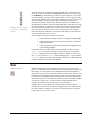
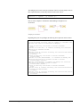
GME 3 Main Editing Window
The figure below shows various features and components associated with the GME
main editing window.
GME 3 Main Editing Window
The GME main editing window has the following components:
•
Titlebar: Indicates the currently loaded project.
•
Menubar: Commands for certain operations on the model.
•
Toolbar: Icon button shortcuts for several editing functions. Placing the
mouse cursor over a toolbar button briefly displays the name/action of
the button.
•
Generic Modeling Environment User's Manual
Modebar: Buttons for selecting and editing modes.
The Generic Modeling Environment • 9
•
Editing area: The main model editing area containing the model
editing windows.
•
Partbrowser: Shows the parts that can be inserted in the current aspect
of the current model.
•
Statusbar: The line at the bottom, which shows status and error
messages, current edit mode (e.g. EDIT, CONNECT, etc.), zoom
factor, paradigm name (e.g. SF), and current time.
•
Attribute Browser: Shows the attributes and preferences of an object.
•
Model Browser: Shows either the aggregation hierarchy of the project,
the type inheritance hierarchy of a model, or a quick overview of the
current modeling paradigm.
These features will be described in detail in later sections.
GME Concepts
As mentioned above, the GME is a generic, programmable tool. However, all GME
configurations are the same on a certain level, simply because “only” the domainspecific modeling concepts and model structures have changed. Before describing
GME operation, we briefly describe the domain-independent modeling concepts
embodied in all GME instances.
Defining the Modeling Paradigm
To properly model any large, complex engineering system, a modeler must be able to
describe a system’s entities, attributes, and relationships in a clear, concise manner.
The modeling environment must constrain the modeler to create syntactically and
semantically correct models, while affording the modeler the flexibility and freedom
to describe a system in sufficient detail to allow meaningful analysis of the models.
Issues such as what is to be modeled, how the modeling is to be done, and what types
of analyses are to be performed on the constructed models must be formalized before
any system is built. Such design choices are represented by the modeling paradigm.
Therefore, creating the modeling paradigm is the first, and most important, step in
creating a DSME.
A modeling paradigm is defined by the kind of models that can be built using it, how
they are organized, what information is stored in them, etc. When GME is tailored
for a particular application domain, the modeling paradigm is determined and the
tool is configured accordingly. Typically the end-users do not change these paradigm
definitions, and they are fixed for a particular instance of GME (of course, they may
change as the design environment evolves).
Examples of modeling paradigms are as follows:
•
Paradigms for modeling signal flow graphs and hardware architecture
for high-performance signal processing domains.
•
Paradigms for process models and equipment models used in chemical
engineering domains.
•
Paradigms for modeling the functionality and physical components of
fault-modeling domains.
•
Paradigms that describe other paradigms. These are referred to as meta
paradigms, and are used to create metamodels. These metamodels are
Generic Modeling Environment User's Manual
The Generic Modeling Environment • 10
then used to automatically generate a modeling environment for the
target domain.
Metamodels are formal
descriptions of concrete
domain specific
environments.
Once an initial modeling paradigm has been formulated, an MGA expert constructs a
metamodel. The metamodel is a UML-based, formal description of the modeling
environment’s model construction semantics. The metamodel defines what types of
objects can be used during the modeling process, how those objects will appear on
screen, what attributes will be associated with those objects, and how relationships
between those objects will be represented. The metamodel also contains a
description of any constraints that the modeling environment must enforce at model
creation time. These constraints are expressed using the standard predicate logic
language, Object Constraint Language (OCL) with some additional features and
limitations according to metamodeling environment of GME. Note that, as
mentioned earlier, metamodels are merely models of modeling environments, and as
such can be built using the GME. A special metamodeling paradigm has been
developed that allows metamodels to be constructed using the GME.
Once a metamodel has been created, it is used to automatically generate a domainspecific GME. The GME is then made available to one or more domain experts who
use it to build domain-specific models. Typically, the domain expert’s initial
modeling efforts will reveal flaws or inconsistencies in the modeling paradigm. As
the modeling paradigm is refined and improved, the metamodel is updated to reflect
these refinements, and new GMEs are generated.
With Interpreters users can
perform analysis on models
or translate them
Once the modeling paradigm is stable (i.e. the MGA and domain experts are
satisfied that the GME allows consistent, valid models to be built), the task of
interpreter writing begins. Interpreters are model translators designed to work with
all models created using the domain-specific GME for which they were designed.
The translated models are used as sources to analysis programs or are used by an
execution environment.
Once the interpreters are created, environment users can create domain models and
perform analysis on those models. Note, however, that model creation usually begins
much sooner. Modelers typically begin creating models as soon as the initial GME is
delivered. As their understanding of the modeling environment and their own
systems grows, the models naturally become more complete and complex.
We now discuss the modeling components in greater detail.
Models
Default icon representing
models in GME
By model we mean an abstract object that represents something in the world. What a
model represents depends on what domain we are working in. For instance,
•
a Dataflow Block is the model for an operator in the signal processing
domain,
•
a Process model represents a functionality in a plant in the chemical
engineering domain,
•
a Network model represents a hardware interconnection scheme in the
multiprocessor architecture domain.
A model is, in computational terms, an object that can be manipulated. It has state,
identity, and behavior. The purpose of the GME is to create and manipulate these
models. Other components of the MGA deal with interpreting these models and
using them in various contexts (e.g. analysis, software synthesis, etc.).
Some modeling paradigms have several kinds of models. For instance:
Generic Modeling Environment User's Manual
The Generic Modeling Environment • 11
•
in a signal processing paradigm there can be Primitive Blocks for
simple operators and Compound Blocks (which may contain both
primitive blocks and other compound blocks) for compound operators.
•
in a multiprocessor architecture modeling paradigm there can be
models for computational Nodes and models for Networks formed from
those nodes.
A model typically has parts—other objects contained within the model. Parts come
in these varieties:
Model with atomic parts as
link ports
•
atoms (or atomic parts),
•
other models,
•
references (which can be thought of as pointers to other objects),
•
sets (which can contain other parts), and
•
connections.
If a model contains parts, we say that the model is the parent of its parts. Parts can
have various attributes. A special attribute associated with atomic parts allows them
to be designated as link parts. Link parts act as connection points between models
(usually used to indicate some form of association, relationship, or dataflow between
two or more models). Models containing other models as parts are called compound
models. Models that cannot contain other models are called primitive models. If a
compound model can contain other models we have a case of model hierarchy.
In the GME, each part (atom, model, reference, or set) is represented by an icon.
Parts have a simple, paradigm-defined icon. If no icon is defined for a model, it is
shown using an automatically generated rectangular icon with a 3D border.
Atoms
Default icon for atoms
Atoms (or atomic parts) are simple modeling objects that do not have internal
structure (i.e. they do not contain other objects), although they can have attributes.
Atoms can be used to represent entities, which are indivisible, and exist in the
context of their parent model.
A primitive model SubGeneratorC containing four atoms
Examples of atoms are as follows:
Generic Modeling Environment User's Manual
The Generic Modeling Environment • 12
•
An output data port on a dataflow block in a signal processing
paradigm.
•
A connection link on a processor model in a hardware description
paradigm.
•
A process variable in a process model in a chemical engineering
paradigm.
Model Hierarchy
As mentioned above, models can contain other models as parts — models of the
same or different kind as the parent model. This is a case of model hierarchy. The
concept can be explained as follows: models represent the world on different levels
of abstraction. A model that contains other models represents something on a higher
level of abstraction, since many details are not visible. A model that does not contain
other models represents something on a lower level of abstraction. This hierarchical
organization helps in managing complexity by allowing the modeler to present a
larger part of the system, albeit with less detail, by using a higher level of
abstraction. At a lower level of abstraction, more detail can be presented, but less of
the system can be viewed at one time.
Examples where hierarchy is useful are as follows:
•
Hierarchical dataflow diagrams in a signal processing paradigm.
•
Process model hierarchy in a chemical engineering paradigm.
•
Hierarchically organized networks of processors in a paradigm
describing multiprocessors.
Compound model SuperGen containing several Generator models
Generic Modeling Environment User's Manual
The Generic Modeling Environment • 13
References
Default icon for references
pointing to null
References are parts that are similar in concept to pointers found in various
programming languages. When complex models are created (containing many,
different kinds of atomic and hierarchical parts), it is sometimes necessary for one
model to directly access parts contained in another. For example, in one dataflow
diagram a variable may be defined, and in another diagram of the system one may
want to use that variable. In dataflow diagrams, this is possible only by connecting
that variable via a dataflow arc, “going up” in the hierarchy until a level is reached
from where one can descend and reach the other diagram (a rather cumbersome
process).
GME offers a better solution – reference parts. Reference parts are objects that refer
to (i.e. point to) other modeling objects. Thus, a reference part can point to a model,
an atomic part of a model, a model embedded in another model, or even another
reference part or a set. A reference part can be created only after the referenced part
has been created, and the referenced part cannot be removed until all references to it
have been removed. However, it is possible to create null references, i.e. references
that do not refer to any objects. One can think of these as placeholders for future use.
Whether a particular reference can be established (i.e. created) or not depends on the
particular modeling paradigm being used.
Examples of references are as follows:
•
References to variables in remote dataflow diagrams in a signal
processing paradigm.
•
References to equipment models in a process model in a chemical
engineering paradigm.
•
References to nodes of a multiprocessor network in a paradigm
describing hardware/software allocation assignments.
As mentioned above, the icon used to represent the reference part is user-defined.
Model (or model reference) references that do not have their own icon defined have
an appearance similar to the referred-to model, but without 3D borders.
Connections and links
Merely having parts in a model is not sufficient for creating meaningful models —
there are relationships among those parts that need to be expressed. The GME uses
many different methods for expressing these relationships, the simplest one being the
connection. A connection is a line that connects two parts of a model. Connections
have at least two attributes: appearance (to aid the modeler in making distinctions
between different types of connections) and directionality (as distinguished by the
presence or absence of an arrow head at the “destination” end of the line). Additional
connection attributes can be defined in the metamodel, depending on the
requirements of the particular modeling paradigm.
The actual semantics of a connection is determined by the modeling paradigm. When
the connection is being drawn, the GME checks whether the connection is legal or
not. All legal connections are defined in the metamodel. Two checks are made to
determine the legality of a connection. First, a check is made to determine if the two
types of objects are allowed to be connected together. Second, the direction of the
connection needs to be checked.
Generic Modeling Environment User's Manual
The Generic Modeling Environment • 14
GME edit mode bar with the
“Connections” mode button
selected.
To make connections, the modeler must place the GME in the “Add Connections”
mode. This is done by clicking on the Connections mode button (see figure to left)
on the Modebar. A connection always connects two parts. If the part is an icon that
represents a model, it may have some connection points, or links. Logically, a link is
a port through which the model is connected to another part within the parent model.
Links on a model icon represent specific parts contained in the model that are
involved in a connection. In these cases, when the connection is established, care
should be taken to build the connection with the right link. The link shows up on the
icon of the model part as a miniature icon with a label. When the connection is built,
the system uses these miniature icons as sensitive “pads” where connections may
start or end. Moving the mouse cursor over one of the pads shows the complete
name of the link part. Furthermore, not only atoms, but models, sets and references
except for connections can act as a ports.
Some examples of connections and links are as follows:
•
Connections between dataflow blocks in a signal processing paradigm.
•
Connections between processes on a process flow sheet of a chemical
engineering paradigm.
•
Connections between failure modes (indicating failure propagation) in
a fault modeling paradigm.
Connections can be seen between atomic parts and models, as in the case of the
Input Signal atomic part connecting to the ports labeled “In” on each of the
Generator models shown earlier, and between ports of models, as in the case of
the “Out” ports of each Generator model connecting to the “In” port of another
Generator model. Notice that, in this paradigm, connections are directional (used
to indicate information flow between the models).
Sets
Default icon for sets
Models containing objects and connections show a static system. In some cases,
however, it is necessary to have a model of a dynamic system that has an architecture
that changes over time. From the visual standpoint this means that, depending on
what “state” the system is in, we should see different pictures. These “states” are not
predefined by the modeling paradigm (in that case they would be aspects), but rather
by the modeler. The different pictures should show the same model, containing the
same kinds of parts, but some of the parts should be “present” while others should be
“missing” in a certain “states.” In other words, the modeler should be able to
construct sets and subsets of particular objects (even connections).
In GME, each set is represented by an icon (user-defined or default). When a
particular set is activated, only the objects belonging to that set are visible (all other
parts in the model are “dimmed” or “grayed out.”) Parts may belong to a single set,
to more than one set, or to no set at all.
Generic Modeling Environment User's Manual
The Generic Modeling Environment • 15
To add or remove parts from sets, the set must first be activated by placing the
graphical editor into Set Mode. This is done by clicking the Set Mode button (see
left) on the edit mode bar. Next, a set is activated by right-clicking the mouse on it.
Once the set has been activated, parts (even connections) may be added and/or
removed using the left mouse button. To return to the Edit Mode, click the Normal
Mode button on the edit mode bar.
The following examples of using sets:
GME edit mode bar with the
“Set” mode button selected.
•
State-dependent configuration of processing blocks in a signal
processing paradigm.
•
State dependent process configuration in a chemical engineering
paradigm.
•
State-dependent failure propagation graphs in a fault modeling
paradigm.
Aspects
As mentioned earlier, we use hierarchy to show or hide design detail within our
models. However, large models and/or complex modeling paradigms can lead to
situations where, even within a given level of design hierarchy, there may be too
many parts displayed at once. To alleviate this problem, models can be partitioned
into aspects.
An aspect is defined by the kinds of parts that are visible in that aspect. Note that
aspects are related to groups of parts. The existence or visibility of a part within a
particular aspect is determined by the modeling paradigm. A given part may also be
visible in more than one aspect. For every kind of part, there are two kinds of
aspects: primary and secondary. Parts can only be added or deleted from the model
from within its primary aspect. Secondary aspects merely inherit parts from the
primary aspects. Of course, different interconnection rules may apply to parts in
different aspects.
When a model is viewed, it is always viewed from one particular aspect at a time.
Since some parts may be visible in more than one aspect while others may visible
only in a single aspect, models may have a completely different appearance when
viewed from different aspects (after all, that’s why aspects exist!)
The following are examples of aspects:
•
“Signal Flow” and “States” aspects for a signal processing paradigm.
•
“Process Flow Sheet” and “Process Finite State Machine” aspects for a
chemical engineering paradigm.
•
“Component Assignment” and “Failure-Propagation” aspects of a faultmodeling paradigm.
Attributes
Models, atoms, references, sets and connections can all have attributes. An attribute
is a property of an object that is best expressed textually. (Note that we use the word
“text” for anything that is shown as text, including numbers, and a choice from a
finite set of symbolic or numeric constants.)
Generic Modeling Environment User's Manual
The Generic Modeling Environment • 16
Typically objects have multiple attributes, which can be set using “non-graphical”
means, such as entry fields, menus, buttons, etc. The attribute values are translated
into object values (e.g. numbers, strings, etc.) and assigned to the objects. The
modeling paradigm defines what attributes are present for what objects, the ranges of
the attribute values, etc. Interpreting these values is left to the model interpreters,
though the users may create constraints using OCL for the attributes to ensure that
their values are valid.
Examples of attributes are as follows:
•
Data type of parameters in a signal processing paradigm.
•
Units for process parameters in a chemical engineering paradigm.
•
Mean-time-between-failure specifications for components in a fault
modeling paradigm.
The attribute box associated with a Parameter atom called Pi.
An object’s attributes can be accessed by right-clicking on the object and selecting
Attributes from the menu, causing the Attribute Browser activated.
Preferences
Preferences are paradigm-independent properties of objects. The five different kinds
of first class objects (model, atom, reference, connection, set) each have a different
set of preferences. The most important preference is the help URL. Others include
color, text color, line type, etc. Preferences are inherited from the paradigm
definition through type inheritance unless this chain is explicitly broken, by
overriding an inherited value. For more details, see the chapter on type inheritance.
Preferences are accessible through the context menus and for the current model
through the Edit menu.
Default preferences can be specified in the paradigm definition file (XML). User
settings can be applied to either the current object, or the kind of object globally in
the project. The checkbox in the preferences dialog box specifies this scope
information. If the “for Kind” checkbox is set, the information is stored in the
compiled, binary paradigm definition file, not in the XML document. This means
that a subsequent parsing of the XML file overwrites preference settings. This
limitation will be eliminated in a later release of GME 3.
Even when the global scope is selected, this only applies to objects that themselves
(or any of their ancestors) have not overridden the given preference.
Generic Modeling Environment User's Manual
The Generic Modeling Environment • 17
Using GME 3
GME 3 Interfaces
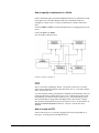
The GME interacts with the user through two major interfaces:
•
the Model Browser, and
•
the Graphical Editor.
Models are stored in a model database and are organized into projects. A project is a
group of models created using a particular modeling paradigm. Within a project, the
models are further organized into modeling folders. Folders themselves and models
in one folder can be organized hierarchically, although standalone models can also
be present.
The Model Browser is used to view or look at the entire project “at a glance.” All
models and folders can be shown, and folders, models and any kind of parts can be
added, moved, and deleted using the Model Browser controls. This is described in
more detail below.
The Part Browser
The Part Browser window shows the parts that can be inserted into the current
model in the current aspect. It shows all parts except for connections. At the bottom
of the Part Browser, tabs show the available aspects of the current model. Clicking
on a tab will change the aspect of the current model to the selected one. It also
attempts to change the aspect of all the open models. If a particular model does not
have the given aspect, its current aspect remains active.
The Part Browser can be used to drag a single object at a time and drop it either in
any editor window or in the Model Browser. If a reference is dragged, a null
reference is created because the target object is unspecified. Remember that
references (null references included) can be redirected at any time by dropping a new
target on top of them (see more detailed discussion where the drag and drop
operations are described).
Note that the Part Browser window, just like the Model Browser window, is
dockable; it can float as an independent window or it can be docked to any side of
the GME 3 Main window.
The Attribute Browser
Attributes and Preferences are available in a modeless dialog box, called the
Attribute Browser. Since there is no OK button, changes are updated immediately.
More precisely, changes to toggle buttons, combo boxes (i.e. menus) and color
Generic Modeling Environment User's Manual
Using GME 3 • 18
pickers are immediate. Changes to single line edit boxes are updated when either
“Enter” is hit on the keyboard or the edit box loses the input focus, i.e. you click
outside the box. The only difference for multiline edit boxes is that they use the
Enter key for new line insertion, so hitting it does not updated the value.
The object selection for the attribute browser works as follows. The context menu
access to Attributes and Preferences, now even from the Model Browser, works.
Furthermore, simply selecting an object or inserting, dropping or pasting it selects
that object for the Attribute browser. If more then one object is selected – in the
Model Browser or in the Model Editor - the attribute browser will allow only the
common attributes of these objects.
At the top of the dialog there are three tabs, one for the attributes one for the
preferences and another for the properties. Note that the Attribute Browser window,
just like the Model Browser window, is dockable; it can float as an independent
window or it can be docked to any side of the GME 3 Main window.
The Model Browser
As mentioned earlier, the GME is a configurable graphical editing environment. It is
configured to work within a particular modeling paradigm via a paradigm definition
file. Paradigm definition files are XML files that use a particular, GME 3 specific
Document Type Definition (DTD). Models cannot be created and edited until a
paradigm definition file (or its compiled, binary version with .mta extension) has
been opened.
Once a project has been loaded, the GME opens a Model Browser window. The
Model Browser is primarily used to organize the individual models that make up an
overall project, while the graphical editor is used for actually constructing the
project’s individual models.
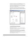
Model Browser showing folders and models.
The most important high-level features of the Model Browser are accessible through
the three tabs displayed at the top of the Model Browser. These tabs deal with the
Aggregate, Inheritance, and Meta hierarchies.
The Aggregate tab contains a tree-based containment hierarchy of all folders,
models, and parts from the highest level of the project, the Root Folder. The
aggregate hierarchy is ignorant to aspects, and is capable of displaying objects of any
kind. More information on the aggregate hierarchy will be provided shortly.
Generic Modeling Environment User's Manual
Using GME 3 • 19
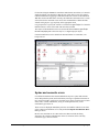
Model Browser with each tab selected
The Inheritance tab is used explicitly for visualizing the type inheritance hierarchy
(described in detail later). It is entirely driven by the current model selection within
the aggregate tree. For example, the current selection in the aggregate tree in the
figure above is a model "GeneratorBase". It has one subtype, called “SubGenBase”,
and two instances, bearing the name “GeneratorA” and “GeneratorB”. This
type/instance relationship is shown in the Inheritance tab. We also have an instance
model of the “SubGenBase” subtype, called “SubGenBase”. In the Aggregate tab
the letter “S” denotes a subtype, while a letter “I” can be found in front of instances.
The Meta tab shows the modeling language at a glance: it displays the legally
available array of Folders and objects that can be added at any level within the
aggregate hierarchy. For example, at the "Root Folder" level we can add "Folder"
folders. Within these folders, we can add models Primitive and Compound. From
these models, more parts can be added.
Model Browser navigation
Arrow keys can navigate the selection in vertical directions. The [Backspace] key
moves the selection to the parent object. The [Delete] key allow for deletion of the
current selection. Object name editing is achieved through delayed clicking on an
object's name. Multiple selection is achieved through [Shift] or [Control] clicks.
Incremental searching is offered for all three tabs through the text entry field
immediately below the Aggregate, Inheritance, and Meta tab selections. The search
is limited to the currently expanded section of the tree to avoid time-consuming
search in a potentially large database. If a global search is desired, pressing the
[Asterisk] key when the root folder is selected fully expands the tree and the search
becomes project-wide.
Most hidden functionality offered within the GME 3 Browser is available through
contextual menus and drag and drop operations. Currently contextual menus are
only offered for selections found within the Aggregate tab. Contextual information
is primarily used for easily inserting new objects based on the current selection, or
for capturing the contents of current selections for Edit functions (Copy, Paste,
Delete, etc.).
Generic Modeling Environment User's Manual
Using GME 3 • 20
Model Browser context menus
Based on the Aggregate tab selection shown above, five different kinds of atoms are
available for insertion (Models can also be inserted, but within this Model we have
specified that the paradigm not allow any References or Sets). Note that connections
cannot be added using the Browser.
Similarly, several Edit options are available in the form of Undo, Redo, Copy,
Paste, etc. Sorting options allow for the all of the objects and their children to be
sorted by a specific style. The Tree Browser Options menuitem displays a dialog
used for specifying the types of objects to be displayed in the Aggregate tab. For
example, the user can choose not to view connections in the browser. To preserve
the state of the aggregate tree (eg.:expanded objects) in the Windows registry the
checkbox in bottom of the options dialog must be set. Interpreting, Constraint
Checking, and context sensitive Help are also available.
Drag and drop is implemented in the standard Windows manner. Multiple selection
items may serve as the source for drag and drop. Modifiers are important to note for
these operations:
•
No modifier: Move operation
•
[Ctrl]: Copy (signified by "plus" icon over mouse cursor)
•
[Ctrl]+[Shift]: Create reference (signified by link icon over mouse cursor)
•
[Alt]: Create Instance (signified by link icon over mouse cursor)
•
[Alt]+[Shift]: Create Sub Type (signified by link icon over mouse cursor)
If a drop operation fails, then a dialog will indicate so. Drop operations can occur
within the Browser itself, allowing this to be an effective means to restructuring a
hierarchy. Drop operations can only be performed onto a Model or a Folder.
Generic Modeling Environment User's Manual
Using GME 3 • 21
Model Browser and Interoperation
Double-clicking on any model in the tree (or pressing the [Space] or [Enter] key
when a model is selected) will open that model for editing in the graphical model
editor. Double-clicking an atom, reference or set, will open up the parent model,
select the given object and scroll the model, so that the object becomes visible.
Locking
Using the MS Repository or ODBC backends, distributed multi-user access is
allowed to the same project. To ensure consistency, GME 3 implements a
sophisticated locking mechanism.
There are four different types of locks from the perspective of a user. An object can
be not locked, read-only locked, write-only locked or exclusively locked. When an
object is read-only locked, then other users may access the same object, but only in
read-only mode. The read-only lock guarantees that all information read from the
object is up-to-date and cannot be modified by other users while the lock is held.
When an object is write-only locked, then others can still access the same object
write-only, but not read-only or exclusively. The write-only lock guarantees that the
object is kept modifiable, while the write-only lock is held. It gives no guarantee,
however, that any information read from the object is up-to-date. Reference objects
are the prime reason for introducing the write-only lock. Multiple users must be
allowed to make references to the same target model. To make matters worse,
different users have different undo queues, possibly containing modifications to the
same objects. Holding a write-only lock on the target model and exclusive locks on
the reference objects solves this problem. Finally, an exclusive lock is equivalent to
holding read-only and write-only locks simultaneously.
In summary, an object is either not locked at all, read-only locked by a few users,
write-only locked by a few users, or exclusively locked by a single user. Note that
the object lock states are visualized in the Model Browser.
The Model Editor
The Editing Window
When a model is selected for editing, an Editor window opens up to allow editing of
that model. The Editor window shows the contents of the selected model in one
aspect at a time.
Generic Modeling Environment User's Manual
Using GME 3 • 22
A typical model Editing window with an open context menu.
A typical Editor window is shown above. The status line near the top begins with an
icon indicating whether the current model is a type (T) or instance (I). Next to it is a
field indicating the model’s name – System in this case. Next to the model’s name
is the kind field, indicating the kind of model (e.g. Connector, Compound,
Network, etc.) being edited. Continuing to the right, the Aspect field indicates
that this model is being viewed in the SignalFlowAspect. Remember, a model’s
appearance, included parts, and connection types can change as different aspects are
selected. Finally, the right side of the status line shows the base type of this model in
case it is a model type (if it is an archetype, it does not have a base type, so the field
shows N/A), or the type model in case the current model is an instance.
GME Menus
On the GME Menubar, the following commands are available:
File: Project- and model-related commands.
The File menu is context-sensitive, with choices depending on whether or
not a paradigm definition file and/or project has been loaded and whether
there is at least one model window open. If no model window is open, the
following items show:
•
New Project: Creates a new, empty project and allows registering a
new modeling paradigm (discussed in detail later).
•
Open Project: Opens an existing project from either a database or a
binary file with the .mga extension (discussed in detail later).
•
Close Project: Saves and closes the currently open project (if any).
•
Save Project: Saves the current project to disk.
•
Save Project As: Saves the current project with a new name.
•
Abort Project: Aborts all the changes made since last save and closes
project.
Generic Modeling Environment User's Manual
Using GME 3 • 23
•
Export XML: GME 3 uses XML (with a specific DTD) as a
export/import file format. This command saves the current project in
XML format.
•
Import XML: Loads a previously exported XML project file. Note that
the file must conform to the DTD specifications in the mga.dtd file. If
no paradigm is loaded, GME 3 tries to locate and load the
corresponding paradigm definitions.
•
Update through XML: Allows updating the current model in case of a
paradigm change. If the user has a project open in one GME 3, while
she modifies the metamodels in another GME 3 and regenerates the
paradigm, this command allows updating the models by automatically
exporting toXML and importing from it. Note that any changes that
invalidate the existing models, for example deleting a model kind that
has instances in the project, will cause this operation to fail. However,
adding new kinds of objects, attributes, etc, or deleting unused concepts
will work.
•
Register Paradigms: Registers a new modeling paradigm (discussed
in detail later).
•
Register Component: Registers an interpreter DLL with the current
paradigm. A dialog box appears that makes it possible to register as
many interpreters as the user wishes.
•
Check All: Invokes the Constraint Manager to check all constraints for
the entire project.
•
Display Constraints: All the constraints defined in the meta-model are
displayed. These constraints can be disabled globally, or on object basis
in this dialog. Options of constraints’ evaluation are also available.
•
Settings: Sets GME 3-specific parameters. Currently, the only
supported options are to set the path where the icon files are located on
the current machine and whether GME should remember the state of
the docking windows. For the paths the user can type in a semicolon
separated list of directories (the order is significant from left to right),
or use the add button in the dialog box to add directories one-by-one
utilizing a standard Windows File Dialog box. Icon directories can be
set for system-wide use or for the current user only. GME 3 searches
first in the user directories followed by the system directories.
•
Exit: Closes GME 3.
Once a model window is open, the following additional items become
available:
•
Run Interpreter: As mentioned earlier, model interpreters are used in
the GME to extract semantic information from the models. This menu
choice invokes the model interpreter registered with the paradigm using
the currently selected model as an argument. Depending on the specific
paradigm and interpreter, such an argument may or may not be
necessary. A submenu makes it possible to select an interpreter if there
is more than one interpreter available.
•
Run Plug-Ins: Plug-ins are paradigm independent interpreters. This
command makes it possible to run the desired one.
•
Check: Invokes the Constraint Manager to check the constraints for the
current model.
Generic Modeling Environment User's Manual
Using GME 3 • 24
•
Print: Allows the user to print the contents of the currently active
window. It scales the contents to fit on one page.
•
Print Setup…: Standard Windows functionality.
After a project has been loaded or created, the following menu items are
active:
Edit: Editing commands.
•
Undo, Redo: The last ten operations can be undone and redone. These
operations are project-based, not model/window-based! The Browser,
Editor, and interpreters share the same undo/redo queue.
•
Clear Undo Queue: Models that can be potentially involved in an
undo/redo operation are locked in the database (in case of a database
backend, as opposed to the binary file format), so that no other user can
have write access to them. This command empties the undo queue and
clears the locks on object that are otherwise not open in the current
GME 3 instance.
•
Project Properties: This command displays a dialog box that makes it
possible to edit/view the properties of the current project. These
properties include its name, author, creation and last modification date
and time, and notes. The creation and modification time stamps are
read-only and are automatically set by GME 3.
Items available only when a model Editor window is open:
•
Show Parent: Active when the current model is contained inside
another model. Selecting this option opens the parent model in a new
editing window.
•
Show Basetype: Active when the current model is a type model but
not an archetype (i.e. it is not a root node in the type inheritance
hierarchy). This command opens the base type model of the current
model in an editing window.
•
Show Type: Active when the current model is an instance model. This
command opens the type model of the current model in an editing
window.
•
Copy, Paste, Delete, Select All: Standard Windows operations.
•
Paste Special: A submenu makes it possible to paste the current
clipboard data as a reference, subtype or instance. Paste Special only
works if the data source is the current project and the current GME 3
instance.
•
Cancel: Used to cancel a pending connect/disconnect operation.
•
Preferences: Shows the preferences available for the current model
(see detailed discussion in a separate section below).
•
Registry: The registry is a property extension mechanism: any object
can contain an arbitrarily deep tree structure of simple key-value pairs
of data. Selecting this menu item opens up a simple dialog box where
the current object’s registry can be edited. Special care must be taken
when editing the registry, since it is being used by the GME 3 GUI to
store visualization information and domain-specific interpreters may
use it too.
Generic Modeling Environment User's Manual
Using GME 3 • 25
•
Synch Aspects: The layout of objects in an aspect is independent of
other aspects. However, using this functionality, the layout in one
source aspect can be propagated to multiple destination aspects. A
dialog box enables the selection of the source and destination aspects.
The objects that participate in this operation can also be controlled
here. The default selection is all the visible objects in the source aspect
if none of them were selected in the editing window, otherwise, only
the selected ones. Two check boxes control the order in which objects
are moved. This is important in case objects compete for the same real
estate. Priority can be given to the selected objects and within the
selected objects the ones that are visible in the source aspect.
View: Allows the toggling on and off of the Toolbar, the Status Bar (bottom of the
main window), the Browser window, the Attribute Browser, and the Part Browser
window.
Window:
•
Cascade, Tile, Arrange Icons: Standard Windows window
management functions.
•
Contents: Accesses the ISIS web server and shows the contents page
Help:
of this document.
•
Help: Shows context-sensitive, user-defined help (if available) or
defaults to the appropriate page of this document. See details in a
subsequent section.
•
About: Standard Windows functionality.
Annotations
GME 3 provides annotations for attaching notes to your models. These multi-line
textual annotations are paradigm independent and available in all of your models.
Annotations are not aligned to the model grid (as opposed to real modeling entities),
and they can overlap each other, but they are always lower in the Z-order than
normal objects. Like every model contained artifact, the visibility and position of
annotations are aspect dependent.
Creating Annotations
You can create a new annotation in an opened model from the context menu Insert
Annotation if you right-click on an empty area in the model. GME generates a name
for your annotation, and normally there is no need to modify this. It also opens the
Annotations dialog where you can customize the text and appearance of your
comment.
Editing Annotations
There are several methods for editing your annotations. You can open the
Annotations dialog from the main menu bar Edit | Annotations or from the context
menu Annotations. You can also launch this dialog with double-clicking on one of
your annotations.
Generic Modeling Environment User's Manual
Using GME 3 • 26
Annotation editor
On the left side of the dialog in the figure above all the annotations in the active
model are available. On the right-hand side panel you can customize the selected
commentary. The Name, Text, Color, Background and Font settings are selfexplanatory. The Visibility sub-panel enables you to fine tune the position and
visibility in an aspect based manner. All the aspects of the active model (and a
special DEFAULT aspect) are listed on the left side. The checkboxes represent the
visibility information in the proper aspect (if an annotation is visible in the
DEFAULT aspect, it is visible in all the others, so in this case the other checkboxes
are irrelevant.) In the X and Y input boxes you can specify the position of your
annotation in a specific aspect (or the default position.) You can also clear (and set to
default) the position with setting the Default Pos check-box.
Implementation issues
Annotations are stored in the registry of the model. All the registry keys and
explanation of them can be found in the table below. The visualization of annotations
is handled by custom decorator COM objects ‘Mga.Decorator.Annotator’), which
use the very same infrastructure as other custom drawing objects.
Generic Modeling Environment User's Manual
Using GME 3 • 27
Registry Key
/annotations
/annotations/<AnnotationName>
/annotations/<AnnotationName>/color
/annotations/<AnnotationName>/bgcolor
/annotations/<AnnotationName>/font
/annotations/<AnnotationName>/aspects
/annotations/<AnnotationName>/aspects/*
/annotations/<AnnotationName>/aspects/
<AspectName>
Description
This is the root registry key for
annotations
The value of this key is the text of the
comment
This key stores the text color of the
comment as a 24 bit hexadecimal
number
This key stores the background color
of the comment as a 24 bit
hexadecimal number
The encoded form of the specified font
(Win32 LOGFONT structure)
The key stores the default position of
the annotation
If this key is defined the annotation is
visible in all aspects
If defined, the annotation is visible in
the specific aspect. If it contains a
position code, this will be the position
of your comment in this aspect.
Managing Paradigms
The Register Paradigm item in the File menu displays a dialog box where the user
can add or modify paradigms. This dialog box is also displayed as the first step of the
New Project command (see below).
Like other items recorded in the Windows registry, paradigms can be registered
either in the current user's own registry
[HKEY_CURRENT_USER/Software/GME/Paradigms] or in the common system
registry [HKEY_LOCAL_MACHINE/Software/GME/Paradigms]. If a paradigm is
registered in both registries, the per-user registry takes precedence. When changing
the registration of paradigms it can be specified where the changes are to be
recorded. Non-administrator users on Windows systems generally do not have write
access to the system registry, so they can only change the per-user registration.
Paradigms are listed by their name, status, connection string and current version ID.
The name is what primarily identifies the paradigm. The status is 'u' (user) or 's'
(system) depending where the paradigm is registered. The connection string specifies
the database access information or the file name in case of binary files. Version ID is
the ID of the current generation of the paradigm.
The registry access mode is selectable in the lower right corner of the dialog box.
Pressing the Add from file… button displays a file dialog where the user can select
compiled binary files (.mta) or XML documents. It is possible to store paradigm
information in MS Repository as well. The Add from DB… is used to specify
paradigms stored in a database, like MS Access.
Generic Modeling Environment User's Manual
Using GME 3 • 28
If the new paradigm specified was not yet registered, it will be added the list of
paradigms. If, however, the paradigm is an update to an existing paradigm, it will
replace the existing one, but the old paradigm is also kept as a previous generation.
(The only exception is when the paradigms are specified in their binary format (i.e.
not XML) and the file or connection name of the new generation corresponds to that
of the previous one.) This way existing models can still be opened with the legacy
paradigms they were created with. For new models, however, the current generation
is used always.
Paradigms can be unregistered using the Remove button. Note that the paradigm file
is not deleted.
Different generations of an existing paradigm can be managed using the
Purge/Select button. This brings up another dialog showing all the generations of
the selected paradigm. One option is to set the current generation, the one used for
creating new models. The other option allows unregistering or also physically
deleting one or several of the previous generations. (Whether the files are deleted is
controlled by the checkbox in the lower right corner.)
Important: New paradigm versions are not always compatible with existing binary
models. If a model is reopened, GME offers the option to upgrade it to the new
paradigm. If the upgrade fails, XML export and re-import is needed (the previous
generation of the paradigm is to be used for export). XML is usually the more robust
technique for model migration; it only fails if the changes in the paradigm make the
model invalid. In such a situation the paradigm should be temporarily reverted to
support the existing model, edited to eliminate the inconsistencies, and then reopened
with the final version of the paradigm.
New Project
Selecting the New Project item in the File menu displays the dialog box described in
the previous section. All the features mentioned are available, plus an additional
button, Create New... which is used to proceed with the creation of a new project.
Once the desired paradigm is selected, pressing the OK button displays another small
dialog where the user can specify whether to store the new project in MS Repository
or a binary file. Pressing OK creates and opens a new blank project. At this point, the
only object available in the project is the root folder shown in the Model Browser.
Using the context menu (right-clicking the Project Name), the user can add folders
and other objects, as defined in the paradigm. Double-clicking a model opens it up in
a new Editor window.
Editor Operations
Using the Editor window the user can edit the models graphically. Menus and
editing operations are context sensitive, preventing illegal model construction
operations. (Note, however, that even a syntactically correct model can be invalid
semantically!) This section gives a brief overview of common editor operations, such
as changing editing modes, creating and destroying models, placing parts, etc.
Editing Modes
The graphical editor has six editing modes – Normal, Add Connection, Delete
Connection, Set Mode, Zoom Mode and Visualization. The Editing Modebar,
Generic Modeling Environment User's Manual
Using GME 3 • 29
located (by default) just to the left of the main editing window, is used to change
between these modes.
GME Editing Mode Bar
The figure above indicates the buttons used to select different editing modes. The
Editing Modebar is a dockable Windows menu button bar. It can be dragged to
different positions in the editor, floated on top of the editing window, or docked to
the side of the editor.
Normal Mode
Normal mode is used to add/delete/move/copy parts within editing windows. Models
(from the Model Browser) and parts (from the Part Browser) may be copied by leftclick-dragging the objects into the Editor window. Standard Windows keyboard
shortcuts [Ctrl-C] to Copy, [Ctrl-V] to Paste) may also be used. A copy operation
(the default when dragging from the Part Browser) is indicated by the small “+”
symbol attached to the mouse cursor during the left-click-drag operation.
Parts and models may be moved and/or copied between models, too. Here, the
normal left-click-dragging operation causes a move operation instead of a copy. To
copy parts and models between or within models, hold down the [Ctrl] key before
dropping.
New parts and models are given a default name (defined in the modeling paradigm).
Right-clicking a part (even connection) brings up a context menu. Choose
Properties to edit/view an object’s properties. Choose Attributes to edit its
paradigm-specific attribute values.
Right-clicking on the background of a model window brings up another context
menu that makes it possible to insert any part that is legal in the current aspect of the
given model.
As mentioned earlier, reference parts act as pointers to objects, providing a reference
to that part or model. References are created by holding down [Ctrl-Shift] while
dropping parts into a new model from another model window or from the Browser.
When dragging a reference from the Part Browser it is not necessary to hold down
any keys because the source already specifies that a reference is to be created. In this
case, however, a null reference is created since there is no target object specified
(similar to using the context menu to insert a reference).
References can be redirected, i.e. the object they refer to can be changed. Simply
drop an object on top of an existing reference, and if the object kind matches, the
reference is redirected. Note that the type hierarchy places restrictions on this
operation as well (see later in the Type Inheritance chapter).
Subtypes and instances of models can be created by holding down [Alt-Shift] and
[Alt] keys respectively during the drop operation. Type inheritance is described in a
separate chapter.
Generic Modeling Environment User's Manual
Using GME 3 • 30
Parts and models may be removed by left-clicking to highlight them, and either
selecting Delete from the Edit menu, or by pressing the [Delete] key. Note that any
connections attached to an object will also be deleted when that part or model is
deleted. Also remember that parts can only be deleted after all references to them
have already been deleted.
Add Connection Mode
This mode allows connections to be made between modeling objects. Connections
may exist between two atomic parts, between two model ports (think of these as
connection points on models), or between an atomic part and a model port.
Remember, however, that connections are a paradigm-specific notion and will only
be allowed between objects specified by the paradigm definition file as being
allowed to be connected together.
Remember that connections are inherently directional in nature. Connections are
made by first placing the editor in the Add Connection Mode, then left-clicking the
source object, followed by left-clicking on the destination object.
It is not necessary to go to this mode to create a connection. Instead, in Edit mode
right clicking on the desired source of a new connection and selecting Connect in
the context menu changes the cursor to the connect cursor. A connection will be
made to the object that is left clicked next. (Or by selecting the Connect command
on the destination object as well.) Note that any other operation, such as mode
change, window change, new object creation, cancels the instant connection
operation.
Remove Connection Mode
By placing the graphical editor in the Remove Connection Mode, connections
between objects can be removed by simply left-clicking on the connection itself or
the source and/or destination parts.
Set Mode
Set parts are added to a model just like any other part. However, their members can
only be specified when the editor is in Set Mode. Once the editor is in this mode,
right-clicking a set will cause all parts (even connections) in the model that are not
part of the given set to be “grayed out.” Left-clicking object toggles their
membership in the set. As they are added/removed to the set, they regain/lose their
color and appearance.
Zoom Mode
The Zoom Mode allows the user the view the models at different levels of
magnification. The supported range is between 10% and 300%. Left clicking
anywhere in a model window zooms in, while right-clicking zooms out. The zoom
level is window-specific.
Visualization Mode
The Visualization Mode allows single objects and collections of objects
(“neighborhoods” of objects) to be visually highlighted with respect to other
modeling objects. This is useful when examining and/or discussing complex models.
To enter the Visualization Mode, select the Visualization Mode button on the GME
editing mode bar (see picture above). This will cause all visible parts and
connections to become “grayed out.” Next, the user may click on objects using either
Generic Modeling Environment User's Manual
Using GME 3 • 31
the left or right mouse buttons to make them fully visible again. Left- and rightclicking have different effects, as described below.
Left-clicking on any part toggles the visibility of the object. For connections, their
source and destination objects are toggled. The user may continue to select parts in
this manner, highlighting/hiding more and more objects. Right-clicking on a part will
toggle the visibility of the object and the objects at the ends of its connections. Note
that exactly those connections are highlighted at any one time that connect
highlighted objects.
Miscellaneous operations
The following operations are only accessible from the toolbar:
•
Toggle grid: At zoom levels 100% or higher a grid can be displayed in
the model editor window. GME objects always snap to this fine grid,
whether they are visible or not, to facilitate alignment of the objects.
•
Refresh: Clicking the paintbrush button forces GME 3 to repaint all the
windows.
In the current model Editpr window there is a selected list of objects highlighted by
little frames. Using the Arrow keys on the keyboard, these objects can be nudged by
one grid cell in the selected direction, provided that there are no collisions. Note that
GME 3 does not allow overlapping objects.
Connections in GME 3 are automatically routed. The user only needs to specify the
end points of a connection and an appropriate route will be automatically generated
that will avoid all objects and try to provide a visually pleasing connection layout.
The built-in context-sensitive help functionality is described in the next section.
Help System
GME 3 provides context-sensitive, user-defined help functionality. This is facilitated
by the “Help URL” preference of objects. This preference is inherited from the
paradigm definition and through the type inheritance hierarchy exactly like any other
object preference. For more information on this inheritance, see the separate chapter
on type inheritance.
When the user selects help on a context menu or the Help menu Help item for the
current model (also the [F1] key), GME 3 looks up the most specific help URL
available for the given object. If no help URL is found, the program defaults to the
appropriate section of the User's Manual located on the ISIS web server.
When the appropriate URL is located, GME 3 invokes the default web browser on
the current machine and displays the contents of the URL. If no network connection
is available, the help system will be unable to display the information unless the web
server is running on the current machine or the URL refers to a local file.
Searching objects
The Search facility in GME 3 has been updated from a plugin to a full ActiveX
component. This allows you to click or double click on a search result and go
Generic Modeling Environment User's Manual
Using GME 3 • 32
directly to that object in GME. Also, the search can stay open while you go back and
forth from GME to the search window.
Types of the search
A snapshot of the Search screen is shown below. Whenever the Search is invoked,
the search screen pops up. The Search window can be opened by executing the Edit
| Find command, using the [CTRL-F] shortcut or clicking the binocular icon in the
toolbar.
The Search provides for three types of searches.
General Search
This search option is used for finding Models, Atoms, Sets and/or Reference objects
in the project. It has the following options which are AND relation with each other:
•
Name – used to specify the name of the object. It takes a Regular
Expression as an input. The Search checks for any names that have
patterns specified by this field.
•
Role Name – used to specify the role name of the object. It takes a
Regular Expression as an input. The Search checks for any role names
that have patterns specified by this field.
•
Kind Name – used to specify the kind name of the object. It takes a
Regular Expression as an input. The Search checks for any kind names
that have patterns specified by this field.
•
Attribute – used to specify the attribute name appearing in the object.
It takes a Regular Expression as an input. The Search checks for any
attributes with names that have patterns specified by this field.
•
Type – specifies the type of the attribute that is being searched for.
•
Value – specifies the value of the attribute being searched for. It can
take in String, Integer, Float and Boolean (0 or 1) values.
Meta-Kind Search
The user can search for objects specifying the meta-kinds. These can be Atoms,
Models, References, Sets. Connections are not supported.
Special Reference Search
The Search for NULL References option is used to look for references pointing to
null. More restrictions can be applied specifying the search criteria. When you
conduct any search, clicking on a search result object will change the “NULL” into
the name of that object. Then the user may search for references pointing to that
object with the special search checkbox. Select the Special Reference Search, then
deselect it to set it back to NULL.
Regular expressions
The Name, Role, Kind & Attribute fields can be specified using the regular
expressions. This section documents the valid input kinds that the Search tool shall
accept.
Regular expressions are case-sensitive.
Generic Modeling Environment User's Manual
Using GME 3 • 33
Check the Match Whole Word Only if you don’t want a Regular Expression based
search for the first four fields.
Syntax of the expressions:
•
Any permutation of characters, numbers & symbols such as “_”, “-” is
valid. A few special symbols that are used are “.”, “*”, “+”, “(”, “)”,
“[”, “]”, “^”, “$”.
•
The regular expression should be well formed, i.e. all the opening
brackets should have corresponding closing brackets.
•
Writing “GME” will mean all the string containing the letters “GME”
will be returned.
•
Writing “GME*” will return all strings containing “GM”, “GME”,
“GMEE”, “GMEEE” and so on.
•
Writing “GME+” is the same as “GME*” with the exception of only
“GM”.
•
Writing “GME.*” is the same as “GME”.
Defaults
The Search functionality has been implemented assuming certain default conditions.
On invocation the search tool has the following default inputs:
•
All the Search for options are selected.
•
The Match Whole Word Only option is not checked.
The inputs can be specified in the following ways:
•
Any of the input boxes being empty implies that the all the objects will
be returned without checking that input.
•
The attribute Type & Value fields require the attribute Name to be
specified.
•
The Value field shall not be considered as a regular expression for
searching the attribute value. The value specified has to be exact.
•
Taking everything to the extreme, as soon as the search tool is invoked,
on pressing the Search button, all the eligible objects will be returned,
if no extra inputs are specified.
Generic Modeling Environment User's Manual
Using GME 3 • 34
Type Inheritance
Type Inheritance Concepts
The type inheritance concepts in GME 3 closely resemble those of object-oriented
programming languages. The only significant difference is that in GME, model types
are similar in appearance to model instances; they too are graphical, have attributes
and contain parts. By default, a model created from scratch is a type. A subtype of a
model type can be created by dragging the type and dropping it while pressing the
[Alt+Shift] key combination. An instance is created in similar manner, but only the
[Alt] key needs to be used.
A subtype or an instance of a model type depends on the type. There is one
significant rule that is different for subtypes and instances. New parts are allowed in
a subtype, but not in an instance. Otherwise, parts can be renamed, set membership
can be changed, and references can be redirected in both subtypes and instances.
Parts cannot be deleted and connections cannot be modified in either subtypes or
instances.
Any modification of parts in a type propagates down the inheritance hierarchy. For
example, if a part is deleted in a type, the same part will be automatically deleted in
all of its instances and subtypes and instances of subtypes all the way down the
inheritance hierarchy.
Types can contain other types as well as instances as parts. The mixture of
aggregation and type inheritance introduces another kind of relationship between
objects. This is best illustrated through an example. In the figure below, there are two
root type models: the Engine and the Car. The car contains an instance of an engine,
V6, and an ABS type model. V6 is an instance of the Engine; this relationship is
indicated by the dash line. Aggregation is depicted by solid lines.
Generic Modeling Environment User's Manual
Type Inheritance • 35
Model Dependency Chains
When we create a subtype of the Car (Cool Car above), we indirectly create another
instance of the Engine (V6) and a subtype of the ABS type. This is the expected
behavior as a subtype without any modification should look exactly like its base
type. Notice the arrow that points from V6 in Cool Car to V6 in Car. Both of these
are instances, but there is a dependency between the two objects. If we modify V6 in
Car, V6 in Cool Car should also be modified automatically for the same reason: if
we don't modify Cool Car it should always look like Car itself. The same logic
applies if we create an instance of Cool Car (My Car above). It introduces a
dependency (among others) between V6 in My Car and V6 in Cool Car. As the
figure shows, this forms a dependency chain from V6 in My Car through V6 in Cool
car and V6 in Car all the way to the Engine type model.
What happens if we modify V6 in Cool Car by changing an attribute? Should an
attribute change in V6 in Car propagate down to V6 in Cool Car and below? No, that
attribute has been overridden and the dependency chain broken with respect to that
attribute. However, if the same attribute is changed in V6 in Cool Car, that should
propagate down to V6 in My Car unless it has already been overridden there. The
same logic applies to preferences.
The figure below shows the same set of models, but only from the pure type
inheritance perspective.
Generic Modeling Environment User's Manual
Type Inheritance • 36
Type Inheritance Hierarchy
Let's summarize the rules of type inheritance in GME 3.
•
Parts cannot be deleted in subtypes or instances.
•
Parts can be added in subtypes only.
•
Part changes in a type model propagate down the type inheritance
hierarchy unconditionally.
•
Aggregation and type inheritance introduce dependency chains between
models.
•
Attribute and preference changes, set membership modification and
reference redirection propagate down the dependency chain. If a
particular setting has been overridden in a certain model in the
dependency chain, that breaks the chain for that setting. Changes up in
the chain do not propagate to the given model or below.
•
The rules for reference redirection are as follows. A null reference in a
type can be redirected in any way that the paradigm allows down the
dependency chain. A reference to a type in a type model can only be
redirected to subtypes or instances of the referred-to type or any
instances of any its subtypes. A reference to an instance model in a type
model cannot be redirected at all down the hierarchy. Obviously, a
reference in an archetype can be redirected in any way the paradigm
allows.
•
To avoid multiple dependency chains between any two objects, in
version 1.1 or older, only root type models could be explicitly derived
or instantiated. This restriction has been relaxed. Now, if none of a type
model’s descendants and ascendants are derived or instantiated, then
the model can be derived or instantiated. This means, for example, that
a model, that has nor subtypes or instances itself, can contain a model
type AND its instances. This relaxed restriction still does not introduce
multiple dependency chains.
Generic Modeling Environment User's Manual
Type Inheritance • 37
Attributes and Preferences
The Attributes and the Preferences tabs each show the items either in gray color or
in black color. Items with gray color have the default or inherited value, which
means that the value is not given explicitly for this object. If the user assigns a new
value to an attribute or preference, the item will be show in black color. An item can
be reset to the inherited value by pressing [Ctrl-D] while the item is active.
References and Sets
As mentioned before, references can be redirected (with some restrictions) and set
membership can be changed in subtypes and instances. The propagation of settings
along the dependency chain is true here too. Changing the settings breaks the
dependency chain for the given object. However, the setting can be easily reset by
selecting the Reset item in the appropriate context menu.
References can also be reset to null by using the Clear item in the context menu.
However, this is only allowed if the container model is an archetype or if the
inherited value of the reference is null itself (otherwise it would violate the rules of
inheritance in GME 3).
Decorator enhancements
Since GME 3 the default decorator is able to display more information about objects
regarding the type inheritance. The user may turn off or on these information in
meta-modeling time or modeling time, too.
•
On models T, S or I letter is displayed according to the object type
information.
•
For instances below the name of the object, the name of the type or
subtype is shown with small font.
Generic Modeling Environment User's Manual
Type Inheritance • 38
Libraries
Model library support
Starting with v 2.0, GME supports model libraries, an important mechanism for
reusing design artifacts. Libraries are ordinary GME projects; indeed every GME
project (including the ones that import libraries themselves) can be imported in a
project as a library. The only prerequisite is that both the library and the target
project are based on the same version of the same paradigm.
When a library is imported, it is copied into the target project in whole, so that the
root folder of the library becomes an ordinary (non-root folder) in the target. The
copy is indicated with a special flag that warrants read-only access to this part of the
target project.
The primary way of using libraries is to create subtypes and instances from the
library objects. It is also possible to refer library objects through references. Apart
from being read-only, objects imported through the library are equivalent to objects
created from scratch.
Library objects can easily be recognized in the tree browser. The library root is
indicated with a special icon, and if the browser displays access icons, all library
objects are marked to indicate read-only access.
To import a library in a project, the Attach library... command of the Model
Browser context menu is used. Evidently, it is possible to attach libraries to folders
only. The folder that receives the library must be a legal container in the root folder
according to the paradigm. Since many paradigms do not allow the root folder to be
instantiated at other points in the model tree, the root folder of any project is exempt
from this rule, i.e. it is possible to attach a library to the root folder even if the
paradigm does not allow that.
If the original library project changes, it is not automatically reflected in the projects
that import it. It is possible, however, to refresh the imported library images through
the Refresh library... function in the browser context menu. It is possible to specify
an alternate name for the library, in case it has been moved, for example.
When a library is refreshed, changes in the library are propagated to the library
image and to the subtypes and instances created from the library objects. During this
process, complex scenarios can occur. First, objects may have been deleted from the
library, which means that images of these objects and associations (references,
connections) to them need to be deleted. Another typical case is when an association
is changed in the library, which requires changing of the associations that depend on
Generic Modeling Environment User's Manual
Libraries • 39
the changed object, and may also require changing other associations (like
connections going through references) as well.
Generally, it is recommended to carefully check the models after a refresh operation,
especially if non-trivial changes were applied to the library. Mapping the old and
new library objects is based on the relative ID-s (RelID-s). Relative ID-s are unique
identifiers of objects belonging to the same parent (i.e. folder or model). When an
object is deleted, its RelID is not reused for a long time (until the RelID space of
about 100 million is not running out), so it is practically safe to identify objects by
RelID-s. The identification based on RelID-s works sufficiently by itself in most
cases. There may be exceptional situations, however, when RelID-s need to be
manually changed to provide a suitable mapping (e.g. when an object is
inadvertently deleted from a library, and must be restored manually). The object
'Properties..' dialog boxes (available through the context menu) can be used to
manually change individual object RelID-s. (When changing RelID-s, be aware that
setting RelID-s incorrectly may corrupt a whole project.)
Generic Modeling Environment User's Manual
Libraries • 40
Decorators
Introduction
GME 3 v1.2 and later implements object drawing in a separate plugable COM
module making domain-specific visual representation a reality. In earlier versions of
GME one could only specify bitmap files for objects. This method is still supported
by the default decorator component shipped with GME 3.
Replacing the default implementation basically consists of two steps. First we have
to create a COM based component, which implements the IMgaDecorator COM
interface. Second, we have to assign this decorator to the classes in our metamodel
(or for the objects in our model(s) if we want to override the default decorator
specified in the metamodel).
GME instantiates a separate decorator for each object in each aspect, so we have to
keep our decorator code as compact as possible. Decorator components always have
to be in-process servers. Using C++, ATL or MFC is the recommended way to
develop decorators.
The IMgaDecorator interface
The following diagram shows the method invocation sequence on the
IMgaDecorator interface. Understanding the protocol between GME and the
decorators is the key to developing decorators. All the methods on the decorator
interface are called by GME (there is no callback mechanism). The direction column
in the diagram shows the direction of the information flow.
GME always calls your methods in a read-only MGA transaction. You must not
initiate new transactions in your decorator. SaveState() method is the only exception
to this rule. This method is called in a read-write transaction, therefore, this is the
only place where you can store decorator specific information in the MGA project.
Generic Modeling Environment User's Manual
Decorators • 41
GME
Dir
=>
Decorator
decorator class constructor
=>
=>
<=
GetFeatures([out] features)
SetParam([in] name, [in]value)
GetParam([in] name, [out] value)
=>
<=
<=
=>
<=
<=
<=
=>
=>
=>
=>
Initialize([in] mgaproject, [in] mgametapart, [in] mgafco)
GetPreferredSize([out] sizex, [out] sizey)
GetPorts([out] portFCOs)
SetLocation([in] sx, [in] sy, [in] ex, [in] ey)
GetPortLocation([in] fco, [out] sx, [out] sy, [out] ex, [out] ey)
GetLabelLocation([out] sx, [out] sy, [out] ex, [out] ey)
GetLocation([out] sx, [out] sy, [out] ex, [out] ey)
SetActive([in] isActive)
Draw([in] hDC)
SaveState()
Destroy()
IMgaDecorator Functions
HRESULT GetFeatures([out] feature_code *features)
This method tells GME which features the decorator supports. Available feature
codes are (can be combined using the bitwise-OR operator):
F_RESIZABLE : decorator supports resizable objects
F_MOUSEVENTS : decorator handles mouse events
F_HASLABEL : decorator draws labels for objects (outside of the object)
F_HASSTATE : decorator wants to save information in the MGA project
F_HASPORTS : decorator supports ports in objects
F_ANIMATION : decorator expects periodic calls of its draw method
HRESULT SetParam([in] BSTR name, [in] VARIANT value)
If there are some parameters specified for this decorator in the meta model, GME
will call this method for each parameter/value pair.
HRESULT GetParam([in] BSTR name, [out] VARIANT *value)
The decorator needs to be able to give back all the parameter/value pairs it got with
the SetParam(…) method.
HRESULT Initialize([in] IMgaProject* project, [in] IMgaMetaPart *meta, [in]
IMgaFCO *obj)
This is your constructor like function. Read all the relevant data from the project and
cache them for later use (it is a better approach than querying the MGA project in
your drawing method all the time). GME will instantiate a new decorator if its MGA
object changes.
Generic Modeling Environment User's Manual
Decorators • 42
HRESULT GetPreferredSize([out] long* sizex, [out] long* sizey)
Your decorator can give GME a hint about the size of the object to be drawn. You
can compute this information based on the inner structure of the object or based on a
bitmap size, or even you can read these values from the registry of the object.
However, GME may not take this information into account when it calls your
SetLocation() method. All the size and location parameters are in logical units.
HRESULT GetPorts([out, retval] IMgaFCOs **portFCOs)
If your decorator supports ports, it should give back a collection of MGA objects that
are drawn as ports inside the decorator. GME uses this method along with successive
calls on GetPortLocation() to figure out where can it find port objects.
HRESULT SetLocation([in] long sx, [in] long sy, [in] long ex, [in] long ey)
You have to draw your object exactly to this position in this size. There is no
exemption to this. GME always calls this method before Draw().
HRESULT GetPortLocation([in] IMgaFCO *fco, [out] long *sx, [out] long *sy,
[out] long *ex, [out] long *ey)
See description of GetPorts(). Position coordinates are relative to the parent object.
HRESULT GetLabelLocation([out] long *sx, [out] long *sy, [out] long *ex,
[out] long *ey)
If you support label drawing, you have to specify the location of the textbox of your
label. This can reside outside of the object. GME will call SetLocation() before this
method.
HRESULT GetLocation([out] long *sx, [out] long *sy, [out] long *ex, [out]
long *ey)
Return the coordinates you got in SetLocation().
HRESULT SetActive([in] VARIANT_BOOL isActive)
GME calls this method with VARIANT_FALSE, if your object must be shown in
gray color. (Eg.: GME was switched into “set” mode.) By default the decorator
should paint its object with the active color.
HRESULT Draw([in] HDC hdc)
You have all the required information when this method is called. Because a
Windows HDC is supplied, the decorator has to be an in-process server. Saving and
restoring this DC in the beginning and at the end of your Draw() method is highly
recommended.
HRESULT SaveState()
Because this is the only method your decorator is in read-write transaction mode, it
has to backup all the permanent data here.
Generic Modeling Environment User's Manual
Decorators • 43
HRESULT Destroy()
A destructor like function. Releasing here all your MGA COM pointers is a good
practice.
Using the Decorator skeleton
You can find a decorkit.zip file in the GME 3 distribution. It contains a skeleton
project for Visual C++ that implements a dumb decorator. Modifying the
DecoratorConfig.h file would be your first step when using the skeleton.
The following modifications have to be made:
•
Give a new value to TYPELIB_UUID (a new ID can be generated by
the guidgen tool, found in Visual Studio)
•
Give a new value to TYPELIB_NAME (at least replace the string
between the parenthesis)
•
Give a new value to COCLASS_UUID (a new ID can be generated by
the guidgen tool, found in Visual Studio)
•
Give a new value to COCLASS_NAME (at least replace the string
between the parenthesis)
•
Give a new value to COCLASS_PROGID (at least replace the last tag
of the string)
•
Give a new value to DECORATOR_NAME
•
Set GME_INTERFACES_BASE to point to the interfaces directory of
your GME
installation
You have to make these modifications only once. When you are upgrading your
decorator SDK, create a backup of your DecoratorConfig.h, and restore it after the
upgrade.
Assigning decorators to objects
You can assign decorators to objects in your meta model or even later in your
model(s). In the MetaGME 3 environment there is a Decorator attribute for each
non-connection FCO where you can specify a ProgID along with optional
parameter/value pairs for a class. The format of this string is as follows:
ProgID param1=value1, param2=value2, …
e.g.:
MGA.Decorator.MetaDecorator showattributes=false, showabstract=true
In your models all the non-connection FCOs have a preference setting called
Decorator. The format of this string is identical to the one in the meta model.
Generic Modeling Environment User's Manual
Decorators • 44
Metamodeling Environment
Introduction
The metamodeling environment has been extended with a new decorator component
in version 1.2 or later. It displays UML classes including their stereotypes and
attributes. Proxies also show this information It resizes UML classes accordingly.
Note that the figures below show the old appearance of metamodels.
GME 3 adds a OCL syntax checker add-on to the metamodeling environment. Every
time a constraint expression attribute is changed, this add-on is activated. Note that
the target paradigm information is not available to this tool, therefore, it cannot
check arguments and parameters, such as kindname. These can only be checked at
constraint evaluation time in your target environment.
Step by step guide to basic metamodeling
The following sections describe the concepts that are used to model the output
Paradigm.
Paradigm
The Paradigm is represented as the model that contains the UML class diagram. The
name of the Paradigm model is the name of the paradigm produced by the
interpreter. The attributes of the Paradigm are Author Information and Version
Information.
Folder
A Folder is represented as a UML class of stereotype «folder». Folders may own
other Folders, FCO’s, and Constraints. Once a Folder contains another container, it
by default contains all FCO’s, Folders, and Constraints that are in that container.
Folders are visualized only in the model browser window of GME 3, and therefore
do not use aspects. A Folder has the Displayed Name, and In Root Folder
attributes.
Generic Modeling Environment User's Manual
Metamodeling Environment • 45
How to specify containment for a Folder
Folder containment applies to Folders and Models that may be contained in a Folder.
In the figure below, the UML diagram outlines the containment scheme of a
paradigm for a sports season. To specify containment for a Folder, follow these
steps.
Create the Folder and item it contains (through insertion, or dragging from the parts
menu)
Connect the item to the Folder
Now, the Folder contains the item.
Example of a Folder containment
FCO
This is a class that is mandatorily abstract. The purpose of this class is to enable
objects that are inherently different (Atom, Reference, Set, etc.) to be able to inherit
from a common base class.
To avoid confusion with the generalization of modeling concepts (Model, Atom, Set,
Connection, Reference) called collectively an “FCO”, and this kind of object in the
metamodeling environment which is called an “FCO”, the metamodeling concept
(that would actually be dragged into a Paradigm model) will be shown in regular
font, while the generalization of types will be in italics as FCO. An FCO has the Is
Abstract and General Preferences attributes. All FCO-s will also have these
attributes.
How to create an FCO
An FCO (like all FCO-s) is created by dragging in the atom corresponding to its
stereotype, or inserting the atom through the menu.
Generic Modeling Environment User's Manual
Metamodeling Environment • 46
How to specify an Attribute for an FCO
Create and configure the Attribute and the FCO.
Connect the Attribute to the FCO
Now, the Attribute belongs to the FCO.
Atom
This class represents an Atom. The Atom is the simplest kind of object in one sense,
because it cannot contain any other parts; but it is complex to define because of the
many different contributions it can make to a Model, Reference, etc.
An Atom has the Icon Name, Port Icon Name, and Name Position attributes.
How to set that an Atom is a Port
Configure the Atom to be a member of a Model
Click on the attributes of the Containment association between the Atom and the
Model
Assert the Object Is A Port attribute.
Reference
To represent a Reference class, two things must be specified: the FCO to which this
Reference refers, and the Model to which the Reference belongs. A Reference has
the Icon Name and Name Position attributes.
How to specify containment of a Reference in a Model
Connect the Reference to the Model
Resolve the prompt for connection type as “Containment”.
How to specify the FCO to which a Reference refers
Connect the Reference to the FCO.
If the FCO is of type Model, an additional prompt is displayed (exactly the same as
when giving ownership to the Model as in the previous step). This time, choose the
“Refer” type of connection. If the FCO is not of type Model, then no additional
input is necessary.
When specifying the roles to which a Reference may refer (that is, if the referred
FCO may play more than one kind of role in a particular Model), the current solution
is that it may refer to all roles of that particular kind. However, in the future, this list
may be modified during paradigm construction through the help of an add-on.
Generic Modeling Environment User's Manual
Metamodeling Environment • 47
Example implementation of a Reference.
Connection
In order for a Connection to be legal within a Model, it must be contained through
aggregation in that Model. The Connection is another highly configurable concept.
The attributes of a Connection include Name Position, 1st destination label, 2nd
destination label, 1st source label, 2nd source label, Color, Line type, Line end, and
Line Start.
How to specify a connection between two Atoms
In addition to Atoms, a Reference to an Atom may also be used as an endpoint of the
Connection. Note that Connection is also usable as an endpoint, but there is
currently no visualization for this concept.
Drag in a Connector Atom (the name of the Connector was deleted in the example
figure)
Connect the source Atom to the Connector
Connect the Connector to the destination Atom
Connect the Connector to the Connection. Resolve the Connection type to
“AssociationClass”
The rolenames of the connections (“src” and “dst”) denote which of the Atoms may
participate as the source or destination of the connection. There may be only one
source and one destination connection to the Connector Atom.
Inheritance is a useful method to increase the number of sources and destinations,
since all child classes will also be sources and destinations.
Currently, all possible FCO source/destination combinations will be used in the
production of the metamodel. However, in future revisions of the metamodeling
environment, the list of allowable connections may be modified at model building
time (to eliminate certain possibilities from ever occurring).
Generic Modeling Environment User's Manual
Metamodeling Environment • 48
Example of a Connection
Set
The Set is a more general case of the Reference. Sets have the Icon name, and
Name Position attributes.
Figure 4 shows an example implementation of a Set. The members of the Set are
“owned” by the Set through the “SetMembership” connection kind (when connecting
the Reference to the Set, the user will be prompted to choose between the
“SetMembership” and “ReferTo” connection kinds). Some underlying assumptions
exist here, such as all members of the Set must be members of the Model to which
this set belongs.
Example implementation of a Set
How to specify what FCO-s a Set “Owns”
Connect the FCO to the Set Atom. In the event of an ambiguity, resolve it with the
SetMembership connection type.
Generic Modeling Environment User's Manual
Metamodeling Environment • 49
Make sure to aggregate the Set to the Model in which it will reside.
Model
The Model may contain (through the “Containment” connection type) any other
FCO, and it associates a role name to each FCO it contains. The Model has the
Name Position and In Root Folder attributes.
How to contain a Model (Model-1) in a Model (Model-0)
Connect Model-1 to Model-0
Note that it is applicable to have a Model contain itself (the previous case where
Model-1 == Model-0).
How to contain an Atom in a Model
In the event that an FCO is used as a superclass for the Model, then FCO may
replace Model in the following sequence. Atom may be replaced by Set, Reference,
or Connection.
Create and configure the Atom and the Model
Connect the Atom to the Model
Attributes
Attributes are represented by UML classes in the GME metamodeling environment.
There are three different kinds of Attributes: Enumerated, Field, and Boolean. Once
any of these Attributes are created, they are aggregated to FCO-s in the Attributes
Aspect. The order of attributes an FCO will have is determined by the relative
vertical location of the UML classes representing the attributes.
Inheritance
Inheritance is standard style for UML. Any FCO may inherit from an FCO kind of
class, but an FCO may inherit only from other FCO’s. Kinds may inherit only from
each other (e.g. Model may not inherit from Atom). When the class is declared as
abstract, then it is used during generation, but no output FCO is generated. No class
of kind FCO is ever generated.
When multiple-inheritance is encountered, it will always be treated as if it were
virtual inheritance. For example, the classic diamond hierarchy will result in only
one grandparent class being created, rather than duplicate classes for each parent.
How to Specify Inheritance
It is assumed that Child and Parent are of the same kind (e.g. Atom, Model). FCO is
used in this example, for brevity, but note that any FCO may participate in the Child
role, if the Parent is of kind FCO. Else, they must match.
Connect the Parent FCO to the Inheritance Atom. This creates a superclass.
Connect the Inheritance atom to the Child FCO. This creates the child class.
Generic Modeling Environment User's Manual
Metamodeling Environment • 50
Aspect
This set defines the visualization that the Models in the destination paradigm will
use. Models may contain Aspects through the “HasAspect” connection kind. This is
visualized using the traditional UML composition relation using a filled diamond.
FCOs that need to be shown in the an aspect must be made members of the given
Aspect set.
GME 3 supports aspect mapping providing precise control over what aspect of a
model is shown in an aspect of the containing model. This is advanced rarely-used
usually feature is typically applied in case a container and a contained models have
disjoint aspect sets. Specifying aspect mapping would be to cumbersome in a UMLlike graphical language. The metamodeling interpreter allows specifying this
information in a dialog box (described in detail later).
Composing Metamodels
The composable metamodeling environment released with GME 3 v1.1, supports
metamodel composition. First, it supports multiple paradigm sheets. Unlike most
UML editors, where boxes representing classes are tied together by name, GME 3
uses references. They are called proxies. Any UML class atom can have multiple
proxies referring to it. These references are visualized by a curved arrow inside the
regular UML class icon. The atom and all its proxies represent the same UML class.
Operators
In addition to improving the usability of the environment and the readability of the
metamodels, the primary motivation behind composable metamodeling is to support
the reuse of existing metamodels and, eventually, to create extensive metamodel
libraries. However, this mandates that existing metamodels remain intact in the
composition, so that changes can propagate to the metamodels where they are used.
The above requirement and limitations of UML made it necessary to develop three
operators for use in combining metamodels together: an equivalence operator, an
implementation inheritance operator, and an interface inheritance operator.
Equivalence operator
The equivalence operator is used to represent the (full) union between two UML
class objects. The two classes cease to be two separate classes, but form a single
class instead. Thus, the union includes all attributes and associations, including
generalization, specialization, and containment, of each individual class. Equivalence
can be thought of as defining the “join points” or “composition points” of two or
more source metamodels.
Implementation inheritance operator
The semantics of UML specialization (i.e. inheritance) are straightforward:
specialized (i.e. child) classes contain all the attributes of the general (parent) class,
and can participate in any association the parent can participate in. However, during
metamodel composition, there are cases where finer-grained control over the
inheritance operation is necessary. Therefore, we have introduced two types of
inheritance operations between class objects—implementation inheritance and
interface inheritance.
Generic Modeling Environment User's Manual
Metamodeling Environment • 51
In implementation inheritance, the subclass inherits all of the base class’ attributes,
but only those containment associations where the base class functions as the
container. No other associations are inherited. Implementation inheritance is
represented graphically by a UML inheritance icon containing a solid black dot.
This can be seen in the left hand side diagram in the figure below, where
implementation inheritance is used to derive class X1 from class B1. In this case, X1
the association allowing objects of type C1 to be contained in objects of type B1. In
other words, X1-type objects can contain C1-type objects. Because B1-type objects
can contain other B1-type objects, X1-type objects can contain objects of type B1
but not of type X1. Note that D1-type objects can contain objects of type B1 but not
objects of type X1.
Interface inheritance operator
The right side of the figure shows interface inheritance between B2 and X2 (the
unfilled circle inside the inheritance icon denotes interface inheritance). Interface
inheritance allows no attribute inheritance but does allow full association inheritance,
with one exception: containment associations where the base class functions as the
container are not inherited. Therefore, in this example, X2-type objects can be
contained in objects of type D2 and B2, but no objects can be contained in X2-type
objects, not even other X2-type objects.
The union of implementation inheritance and interface inheritance is the normal
UML inheritance. It should also be noted that these operators could have been
implemented using UML stereotypes. However, interface and implementation
inheritance are semantically much closer to regular inheritance than to associations.
Therefore, the use of association with stereotypes would be misleading.
Implementation and interface inheritance operators
Aspect equivalence
Since classes representing Aspects show up only in the Visualization aspect, another
operator is used to express the equivalence of aspects, called the SameAspect
operator. While aspects can have proxies as well, they are not sets any more; they are
references. Hence, they cannot be used to add additional objects to the aspect. In this
case, a new aspect needs to be created. New members can be added to it, since it is a
set. Using the SameAspect operator and typically a proxy of another aspect, the
equivalence of the two aspects can be expressed.
Note that having two aspects with the same name without explicitly expressing the
equivalence of them will result in two different aspect in the target modeling
paradigm.
The name of the final aspect is determined by the following rules. If an equivalence
is expressed between a proxy and a UML class, the name of the class is used. If one
Generic Modeling Environment User's Manual
Metamodeling Environment • 52
of them is abstract and the other is not, the name of the non-abstract class (or proxy)
is used. If both aspects are proxies (or classes), then the name of the SameAspect
operator is used.
Currently, the order of aspects in the target paradigm is determined by the relative
vertical position of the aspect set icons in the metamodels.
Folder equivalence
The equivalence of folders can be expressed using the SameFolder operator.
Generating the Target Modeling Paradigm
Once the Paradigm Model is complete, then comes time to interpret the Model.
Interpretation can be initiated from any model. After extensive consistency checking,
the interpreter displays a dialog box where aspect mapping information can be
specified.
Aspect Mapping
The dialog box contains as many tabs as there are distinct aspects in the target
environment. Under each tab a listbox displays all possible model-role combinations
in the first column. The second column presents the available aspects for the given
model and model reference (i.e. in the specified role) in a combo box. The default
selection is the aspect with the same name as the container models aspect. For all
other FCOs (atoms, sets, connections) this files shows N/A.
The third column is used to specify whether the given the aspect is primary or not for
the given FCO (i.e. in the specified role). In a primary aspect, the given FCO can be
added or deleted. In a secondary aspect, it only shows up, but cannot be added or
deleted.
Note that all the information provided by the user through this dialog box is
persistent. It is stored in the metamodel, in the registry of the corresponding objects.
A subsequent invocation of the interpreter will show the dialog box with the
information specified by the user the previous time.
Attribute Guide
Each attribute of any given FCO in the Metamodeling environment has a specific
meaning for the output paradigm. This section describes each attribute, and lists the
FCO(s) in which the attribute resides. Attributes are listed by the text prompted on
the screen for their entry. The section also gives what special instructions (if any)
are necessary for filling out the attribute.
For fields, if the default value of the field is “”, then no default value is specified in
the description. All other attributes list the default value.
1st source label
String value that gives the name of the Attribute class to be displayed there. The
Attribute should also belong (through aggregation) to the Connection. Then, the
value of that Attribute will be displayed in the first position at the end of the source
of the connection.
Generic Modeling Environment User's Manual
Metamodeling Environment • 53
Contained in – Connection
2
nd
source label
String value that gives the name of the Attribute class to be displayed there. The
Attribute should also belong (through aggregation) to the Connection. Then, the
value of that Attribute will be displayed in the second position at the end of the
source of the connection.
Contained in – Connection
1st destination label
String value that gives the name of the Attribute class to be displayed there. The
Attribute should also belong (through aggregation) to the Connection. Then, the
value of that Attribute will be displayed in the first position at the end of the
destination of the connection.
Contained in – Connection
2
nd
destination label
String value that gives the name of the Attribute class to be displayed there. The
Attribute should also belong (through aggregation) to the Connection. Then, the
value of that Attribute will be displayed in the second position at the end of the
destination of the connection.
Contained in – Connection
Abstract
Boolean checkbox that determines whether or not the FCO in question will actually
be generated in the output paradigm. If the checkbox is checked, then no object will
be created, but all properties of the FCO will be passed down to its inherited children
(if any).
Default value – Unchecked
Contained in – FCO, Atom, Model, Set, Connection, Reference
Author information
A text field translated into a comment within the paradigm output file.
Contained in – Paradigm
Cardinality
Text field that gives the cardinality rules of containment for an aggregation.
Default value – 0..*
Contained in – Containment, FolderContainment
Color
String value that gives the default color value of the connection (specified in hex, ex:
0xFF0000).
Default value – 0x000000 (black)
Contained in – Connection
Generic Modeling Environment User's Manual
Metamodeling Environment • 54
Composition role
Text field that gives the rolename that the FCO will have within the Model.
Contained in – Containment
Constraint Equation
Multiline text field that gives the equation for the constraint.
Contained in – Constraint
Context
Text field that specifies the context of a Constraint Function.
Contained in – ConstraintFunc
Data type
Enumeration that gives the default data type of a FieldAttr. The possible values are
String, Integer, and Double.
Default value – String
Contained in – FieldAttr
Decorator
Test field that specifies the decorator component to be used to display the given
object in the target environment. Example: MGA.Decorator.MetaDecorator
Contained in – Model, Atom, Reference, Set
Default = ‘True’
A boolean checkbox that describes the default value of a BooleanAttr.
Default value – Unchecked
Contained in – BooleanAttr
Default parameters
Text field that gives the default parameters of the constraint.
Contained in – Constraint
Default menu item
Text field that gives the displayed name of the menu item in the Menu items
attribute to be used as the default value of the menu.
Contained in – EnumAttr
Description
Text field that is displayed when the constraint is violated.
Contained in – Constraint
Generic Modeling Environment User's Manual
Metamodeling Environment • 55
Displayed name
String value that gives the displayed name of a Folder or Aspect. This will be the
value that is shown in the model browser, or aspect tab (respectively). A blank value
will result in the displayed name being equal to the name of the class.
Contained in – Folder, Aspect
Field default
Text field that gives the default value of the FieldAttr.
Contained in – FieldAttr
General preferences
Text field (multiple lines) that allows a user to enter data to be transferred directly
into the XML file. This is a highly specific text area, and is normally not used. The
occasions for using this area is to configure portions of the paradigm that the
Metamodeling environment has not yet been developed to configure.
Contained in – FCO, Atom, Model, Set, Connection, Reference
Global scope
A boolean checkbox that refers to the definition scope of the attribute. In most cases,
it is sufficient to leave this attribute in its default state (true). The reason for giving
the option of scope is to be able to include attributes with the same names in
different FCO-s, and have those attributes be different. In this case, it is necessary to
include local scoping (i.e. remove the global scope), or the paradigm file will be
ambiguous.
Default value – Checked
Contained in – EnumAttr, BooleanAttr, FieldAttr
Icon
Text field that gives the name of a file to be displayed as the icon for this object.
Contained in – Atom, Set, Reference, Model
In root folder
Boolean checkbox that determines whether or not this object can belong in the root
folder. Note that if an object cannot belong to the root folder, then it must belong to
a Folder or Model (somewhere in its containment hierarchy) that can belong to the
root folder.
Default value – Checked
Contained in – Folder, Model, Atom, Set, Reference
Line end
Enumeration of the possible end types of a line. Possible types are Butt (no special
end), Arrow, and Diamond.
Default value – Butt
Contained in – Connection
Generic Modeling Environment User's Manual
Metamodeling Environment • 56
Line start
Enumeration of the possible start types of a line. Possible types are Butt (no special
end), Arrow, and Diamond.
Default value – Butt
Contained in – Connection
Line type
Enumeration of the possible types of a line. Possible types are Solid, and Dash.
Default value – Solid
Contained in – Connection
Number of lines
Integer field that gives the number of lines to display for this FieldAttr.
Default value – 1
Contained in – FieldAttr
Menu items
A text field that lists the items in an EnumAttr. There are two modes for this text
field (which can also be called a text box, because it has the ability for multiple
lines).
In basic mode, the field items are separated by carriage returns, in the order in which
they should be listed in the menu. In this case, the text used as the menu will be the
same as value of the menu.
In the expanded mode, it is possible to list the definite values to be used for the menu
elements. This is done by separating the displayed value from the actual value with
a comma (,).
Example:
Sample enumerated attribute specification
Note that the displayed and actual value need not be of the same basic type
(character, integer, float, etc.) because it will all be converted to text.
Contained in – EnumAttr
Generic Modeling Environment User's Manual
Metamodeling Environment • 57
Name position
Enumeration that lists the nine places that the name of an FCO can be displayed.
Default value – South
Contained in – Atom, Set, Reference, Model
Object is a port
Boolean checkbox that determines whether or not the FCO will be viewable as a port
within the model.
Default value – Unchecked
Contained in – Containment
On…
The Constraint has many attributes which are similar, except for the type of event to
which they refer. They are all boolean checkboxes that give the constraint manager
the authority to check this constraint when certain events occur (e.g. Model
creation/deletion, connecting two objects). For more information on the semantics of
these events, please refer to the constraint manager documentation.
•
On close model
•
On new child
•
On delete
•
On disconnect
•
On connect
•
On derive
•
On change property
•
On change assoc.
•
On exclude from set
•
On include in set
•
On move
•
On create
•
On change attribute
•
On lost child
•
On refer
•
On unrefer
Default value – Unchecked
Contained in – Constraint
Port icon
Text field that gives the name of a file to be displayed as the port icon for this object.
If no entry is made for this field, but the object is a port, then the normal icon will be
scaled to port size.
Generic Modeling Environment User's Manual
Metamodeling Environment • 58
Contained in – Atom, Set, Reference, Model
Priority (1=High)
Enumeration of the possible levels of priority of this constraint. For more
information on constraint priority, refer to the constraint manager.
Contained in – Constraint
Prompt
A text field translated into the prompt of an attribute. It is in exact WYSIWYG
format (i.e. no ‘:’ or ‘-‘ is appended to the end).
Contained in – EnumAttr, BooleanAttr, FieldAttr
Return type
Text field that specifies the type a Constraint Function.returns.
Contained in – ConstraintFunc
Rolename
Text field that gives the rolename that the FCO will have in the Connection. There
are two different possible default values, ‘src’ and ‘dst’, depending upon whether the
connection was made from the Connector to the FCO, or the FCO to the Connector.
Default value – src or dst
Contained in – SourceToConnector, ConnectorToSource
Stereotype
Enumeration field that specifies how a Constraint Function can be called.
•
attribute
•
method
Default value – method
Contained in – ConstraintFunc
Type displayed
A boolean checkbox that decides whether the name of Type or Subtype of an
Instance has to be displayed or not.
Default value – Unchecked
Contained in – FCO, Atom, Model, Set
Typeinfo displayed
A boolean checkbox that decides whether ‘T’, ‘S’ or ‘I’ letter is displayed according
to that the concrete model is Type, Subtype or Instance. A model does not have any
sign if it is not in type inheritance.
Default value – Checked
Contained in – Model
Generic Modeling Environment User's Manual
Metamodeling Environment • 59
Version information
A text field translated into a comment within the paradigm output file. The user is
responsible for updating this field.
Contained in – Paradigm
Viewable
A boolean checkbox that decides whether or not to display the attribute in the
paradigm. If the state is unchecked, then the attribute will be defined in the
metamodel, but not viewable in any Aspect (regardless of the properties of the FCO.
This is useful if you want to store attributes outside the user’s knowledge.
Default value – Checked
Contained in – EnumAttr, BooleanAttr, FieldAttr
Semantics Guide to Metamodeling
The following table displays the representation of the concepts of GME 3, and how
they translate semantically into core MGA concepts.
Generic Modeling Environment User's Manual
Metamodeling Environment • 60
Stereotype/name
Context
Semantics [& Implications]
First Class Objects (FCO’s)
«model»
«atom»
«connection»
A class
A class
A class
The class is an MGA model
The class is an MGA atom
The class is an MGA connection (must be used as an
Association Class
The class is an MGA reference
The class is an MGA set
The class is a base type of another FCO
«reference»
«set»
«FCO»
A class
A class
A class (abstract only)
Containment
An association (with diamond) between
a «model» and an FCO
An association between a «connection»
(class) and an Association Connector
(models the connection join).
A directed association between a
«reference» and a «model», «atom», or
«reference»
Associations
AssociationClass
ReferTo
The «model» contains the specified FCO as a part.
The «connection» contains all of the roles that the
Association Connection has.
The instances of the «reference» class will refer to
the instances of the «model», «atom», or «reference»
class.
Association Classes
«connection»
An association between a src/dst pair
(or an n-ary connection, in the general
sense) that is attributed by a
«connection» class
The «connection» class represents the src/dst pair(s)
as an MGA connection. [note: the «connection» is an
FCO]
Containment
FolderContainment
FolderContainment
Containment
SetMembership
HasAspect
An association (with diamond) between
a «folder» and a «folder»
An association (with diamond) between
a «folder» and an FCO
An association (with diamond) between
a «model» and an FCO
An association (with diamond) between
a «set» and an FCO
An association between a «model» and
an «aspect»
The «folder» contains 0..n of the associated «folder»
as a legal sub-folder
The «folder» contains 0..n of the associated FCO as a
legal root-object
The «model» contains the associated FCO which
plays a specified role
The «set» may contain the associated FCO.
The «model» contains the specified «aspect».
Cardinality
(none)
An integer attribute for each end of the
association
«aspect»
«folder»
(none)
A class
A class
The model represents a Project
(none)
UML Inheritance
Connector
FCO
Referenceable
Atom, reference, (port), (reference port)
Model, atom, reference, connection, set
Model, atom, reference
This end of the association has the cardinality
specified [unspecified cardinality is assumed to be 1]
Various
The class denotes an MGA aspect
The class denotes an MGA folder
An MGA Project
Inheritance
The class inherits from a superclass. An attribute of
the destination is the rolename to be used for the
child class.
Groups of parts
Generic Modeling Environment User's Manual
The part may play a role in a connection
The part is a first class object
The part may be referenced
Metamodeling Environment • 61
High-Level Component Interface
Introduction to the Component Interface
The process of accessing GME 3 models and generating useful information, e.g.
configuration files for COTS software, database schema, input for a discrete-event
simulator, or even source code, is called model interpretation. GME provides two
interfaces to support model interpretation. The first one is a COM interface that lets
the user write these components in any language that supports COM, e.g. C++,
Visual Basic or Java. The COM interface provides the means to access and modify
the models, their attributes and connectivity. In short, the user can do everything that
can be done using the GUI of the GME. There is a higher-level C++ interface that
takes care of a lot of lower level issues and makes component writing much easier.
This high-level C++ component interface is the focus of this chapter.
Interpreters are typical, but not the only components that can be created using this
technology. The other types are plugins, i.e. components that provide some useful
additional functionality to ease working in GME. These components are very similar
to interpreters, though they are paradigm-independent. For example, a plugin can be
developed to search or locate objects based on some user defined criteria, like the
value of an attribute.
What Does the Component Interface Do?
The component interface is implemented on the top of the COM interface. When the
user initiates model interpretation, the component interface creates the so-called
Builder Object Network (BON). The builder object network mirrors the structure of
the models: each model, atom, reference, connection, etc. has a corresponding
builder object. This way the interface shields the user from the lower level details of
the COM interface and provides support for easy traversal of the models along either
the containment hierarchy, the connections, or the references. The builder classes
provide general-purpose functionality. The builder objects are instances of these
predefined paradigm independent classes. For simple paradigm-specific or any kind
of paradigm independent components, they are all the user needs. For more
complicated components, the builder classes can be extended with inheritance. By
using a pair of supplied macros, the user can have the component interface
instantiate these paradigm-specific classes instead of the built-in ones. The builder
object network will have the functionality provided by the general-purpose interface
extended by the functionality the component writer needs.
Generic Modeling Environment User's Manual
High-Level Component Interface • 62
Component Interface Entry Point
The Builder.h file in component source package defines the high-level C++
component interface. The entry point of the component is defined in the
Component.h in the appropriate subdirectory of the components directory. Here is
the file at the start of the component writing process:
#ifndef GME_INTERPRETER_H
#define GME_INTERPRETER_H
#include "Builder.h"
#define NEW_BON_INVOKE
//#define DEPRECATED_BON_INVOKE_IMPLEMENTED
class CComponent {
public:
CComponent() : focusfolder(NULL) { ; }
CBuilderFolder *focusfolder;
CBuilderFolderList selectedfolders;
void InvokeEx(CBuilder &builder,CBuilderObject *focus,
CBuilderObjectList &selected, long param);
// void Invoke(CBuilder &builder,
CBuilderObjectList &selected, long param);
};
#endif // whole file
Before GME 3 version 1.2 this used to be simpler, but not as powerful. The Invoke
function of the CComponent class used to be the entry point of the component. When
the user initiates interpretation, first the builder object network is created then the
above function is called. The first two parameters provide two ways of traversing the
builder object network. The user can access the list of folders through the CBuilder
instance. Each folder provides a list of builder objects corresponding to the root
models and subfolders. Any builder can then be access through recursive traversal of
the children of model builders.
The CBuilderModelList contains the builders corresponding to the models selected
at the time interpretation was started. If the component was started through the main
window (either through the toolbar or the File menu) then the list contains one model
builder, the one corresponding to the active window. If the interpretation was started
through a context menu (i.e. right click) then the list contains items for all the
selected objects in the given window. If the interpretation was started through the
context menu of the Model Browser, then the list contains the builders for the
selected models in the browser.
Using this list parameter of the Invoke function makes it possible to start the
interpretation at models the user selects. The long parameter is unused at this point.
In version 1.2, Invoke has been replaced by InvokeEx, which clearly separates the
focus object from the selected objects. (Depending on the invocation method both of
these parameters may be empty.) To maintain compatibility with existing
components, the following preprocessor constants have been designated for inclusion
in the Component.h file:
- NEW_BON_INVOKE: if #defined in Component.h, indicates that the new BON is
being used. If it is not defined (e.g. if the Component.h from an old BON is being
used) the framework works in compatibility mode.
Generic Modeling Environment User's Manual
High-Level Component Interface • 63
- DEPRECATED_BON_INVOKE_IMPLEMENTED: In most cases, only the
CComponent::InvokeEx needs to be implemented by the component programmer,
and the ImgaComponent::Invoke() method of the original COM interface also results
in a call to InvokeEx. If, however the user prefers to leave the existing
Component::Invoke() method to be called in this case, the #define of this constant
enables this mode. InvokeEx() must be implemented anyway (as
NEW_BON_INVOKE is still defined).
- IMPLEMENT_OLD_INTERFACE_ONLY: this constant can be included in old
Component.h files only to fully disable support for the IMgaComponentEx COM
interface (GME invokes to the old interface if the InvokeEx is not supported). Using
this constant is generally not recommended.
If none of the above constants are defined, the BON framework interface is
compatible with the old Ccomponent classes. Censequently, older BON code
(Component.h and Component.cpp) can replace the corresponding skeleton/example
files provided in the new BON. When using such a component, however, a warning
is message is displayed to remind users to upgrade the component code to one fully
compliant with the new BON. Although it is strongly recommended to update the
component code (i.e converting CComponent::Invoke to CComponent::InvokeEx(),
this warning can also be supressed by disabling the new COM component interface
through the inclusion of the #define IMPLEMENT_OLD_INTERFACE_ONLY
definition into the old Component.h file.
Plung-Ins are paradigm-independent components. The example Noname plug-in
displays a message. The implementation is in the component.cpp file shown below:
#include "stdafx.h"
#include "Component.h"
void CComponent:: InvokeEx(CBuilder &builder,CBuilderObject *focus,
CBuilderObjectList &selected, long param)
{
AfxMessageBox("Plug-In Sample");
}
The component.h and component.cpp files are the ones that the component writer
needs to expand to implement the desired functionality.
Component Interface
Class diagram of Builder Object Network
Generic Modeling Environment User's Manual
High-Level Component Interface • 64
The simple class structure of the component interface is shown below. Note that each
class is a derivative of the standard MFC CObject class.
As noted before, the single instance of the CBuilder class provides a top level entry
point into the builder object network. It provides access to the model folders and
supplies the name of the current project. The public interface of the CBuilder class is
shown below.
class CBuilder : public CObject {
public:
CBuilderFolder *GetRootFolder() const;
const CBuilderFolderList *GetFolders() const;
CBuilderFolder *GetFolder(CString &name) const;
CString GetProjectName() const;
};
The CBuilderFolder class provides access to the root models of the given folder. It
can also be used to create new root models.
class CBuilderFolder : public CObject {
public:
const CString& GetName() const;
const CBuilderModelList *GetRootModels() const;
const CBuilderFolderList *GetSubFolders() const
CBuilderModel *GetRootModel(CString &name) const;
CBuilderModel *CreateNewModel(CString kindName);
};
The CBuilderObject is the base class for several other classes. It provides a set of
common functionality for models, atoms, references, sets and connections. Some of
the functions need some explanation.
The GetAttribute() functions return true when their successfully retrieved the value
of attribute whose name was supplied in the name argument. If the type of the val
argument does not match the attribute or the wrong name was provided, the function
return false. For field and page attributes, the type matches that of specified in the
meta, for menus, it is a CString and for toggle switches, it is a bool.
The GetxxxAttributeNames functions return the list of names of attributes the given
object has. This helps writing paradigm-independent components (plug-ins).
The GetReferencedBy function returns the list of references that refer to the given
object (renamed in v1.2 from GetReferences).
The GetInConnections (GetOutConnection) functions return the list of incoming
(outgoing) connections from the given object. The string argument specifies the
name of the connection kind as specified by the modeling paradigm. The
GetInConnectedObjects (GetOutConnectedObjects) functions return a list of objects
instead. The GetDirectInConnections (GetDirectOutConnections) build a tree. The
root of the tree is the given object, the edges of the tree are the given kind of
connections. The function returns the leaf nodes. Basically these functions find paths
to (from) the given object without the component writer having to write the traversal
code.
Generic Modeling Environment User's Manual
High-Level Component Interface • 65
The TraverseChildren virtual functions provide a ways to traverse the builder object
network along the containment hierarchy. The implementation provided does not do
anything, the component writer can override it to implement the necessary
functionality. As we'll see later, the CBuilderModel class does override this function.
It enumerates all of its children and calls their Traverse method.
class CBuilderObject : public CObject {
const CString& GetName();
const bool SetName(CString newname);
void GetNamePath(CString &namePath) const;
const CString& GetKindName() const;
const CString& GetPartName() const;
const CBuilderModel *GetParent() const;
CBuilderFolder* GetFolder() const;
bool GetLocation(CString &aspectName,CRect &loc);
bool SetLocation(CString aspectName,CPoint loc);
void
void
void
void
DisplayError(CString &msg) const;
DisplayError(char *msg) const;
DisplayWarning(CString &msg) const;
DisplayWarning(char *msg) const;
bool
bool
bool
bool
bool
bool
GetAttribute(CString &name,CString &val) const;
GetAttribute(char *name,CString &val) const;
GetAttribute(CString &name,int &val) const;
GetAttribute(char *name,int &val) const;
GetAttribute(CString &name,bool &val) const;
GetAttribute(char *name,bool &val) const;
bool SetAttribute(CString &name, CString &val);
bool SetAttribute(CString &name, int val);
bool SetAttribute(CString &name, bool val);
void GetStrAttributeNames(CStringList &list) const;
void GetIntAttributeNames(CStringList &list) const;
void GetBoolAttributeNames(CStringList &list) const;
void GetReferencedBy(CBuilderObjectList &list) const;
const
const
const
const
CBuilderConnectionList
CBuilderConnectionList
CBuilderConnectionList
CBuilderConnectionList
Generic Modeling Environment User's Manual
*GetInConnections(CString &name) const;
*GetInConnections(char *name) const;
*GetOutConnections(CString name)const;
*GetOutConnections(char *name) const;
High-Level Component Interface • 66
bool GetInConnectedObjects(const CString &name,
CBuilderObjectList &list);
bool GetInConnectedObjects(const char *name, CBuilderObjectList &list);
bool GetOutConnectedObjects(const CString &name,
BuilderObjectList &list);
bool GetOutConnectedObjects(const char *name,
CBuilderObjectList &list);
bool
bool
bool
bool
GetDirectInConnections(CString &name, CBuilderObjectList &list);
GetDirectInConnections(char *name, CBuilderObjectList &list);
GetDirectOutConnections(CString &name, CBuilderObjectList &list);
GetDirectOutConnections(char *name, CBuilderObjectList &list);
virtual void TraverseChildren(void *pointer = 0);
};
The CBuilderModel class is the most important class in the component interface,
simply because models are the central objects in the GME. They contain other
objects, connections, sets, they have aspects etc. The GetChildren function returns a
list of all children, i.e. all objects the model contains (models, atoms, sets, references
and connections). The GetModels method returns the list of contained models. If a
role name is supplied then only the specified part list is returned. The GetAtoms,
GetAtomReferences and GetModelReferences, GetSets() functions work the same
way except that a part name must be supplied to them. The GetConnections method
return the list of the kind of connections that was requested. These are the
connections that are visible inside the given model.
The GetAspectNames function return the list of names of aspects the current model
has. This helps in writing paradigm-independent components.
Children can be created with the appropriate creation functions. Similarly,
connections can be constructed by specifying their kind and the source and
destination objects. Please, see the description of the CBuilderConnection class for a
detailed description of connections.
The TraverseModels function is similar to the TraverseChildren but it only traverses
models.
class CBuilderModel : public CBuilderObject {
public:
const CBuilderObjectList *GetChildren() const;
const CBuilderModelList *GetModels() const;
const CBuilderModelList *GetModels(CString partName) const;
const CBuilderAtomList *GetAtoms(CString partName) const;
const CBuilderModelReferenceList *GetModelReferences( CString
refPartName) const;
const CBuilderAtomReferenceList *GetAtomReferences( CString refPartName )
const;
const CBuilderConnectionList *GetConnections(CString name) const;
const CBuilderSetList *GetSets(CString name) const;
void GetAspectNames(CStringList &list);
Generic Modeling Environment User's Manual
High-Level Component Interface • 67
CBuilderModel *CreateNewModel(CString partName);
CBuilderAtom *CreateNewAtom(CString partName);
CBuilderModelReference *CreateNewModelReference(CString refPartName,
CBuilderObject* refTo);
CBuilderAtomReference *CreateNewAtomReference(CString refPartName,
CBuilderObject* refTo);
CBuilderSet *CreateNewSet(CString partName);
CBuilderConnection *CreateNewConnection(CString connName,
CBuilderObject *src, CBuilderObject *dst);
virtual void TraverseModels(void *pointer = 0);
virtual void TraverseChildren(void *pointer = 0);
};
The CBuilderAtom class does not provide any new public methods.
class CBuilderAtom : public CBuilderObject {
public:
};
The CBuilderAtomReference class provides the GetReferred function that returns the
atom (or atom reference) referred to by the given reference.
class CBuilderAtomReference : public CBuilderObject {
const CBuilderObject *GetReferred() const;
};
Even though the GME deals with ports of models (since models cannot be connected
directly, these are the objects that can be), the component interface avoids using
ports for the sake simplicity. However, model references mandate the introduction of
a new kind of object, model reference ports. A model reference contains a list of port
objects. The GetOwner method of the CBuilderReferencePort class return the model
reference containing the given port. The GetAtom method returns the atom that
corresponds to the port of the model that the model reference port represents.
class CBuilderReferencePort : public CBuilderObject {
public:
const CBuilderModelReference *GetOwner() const;
const CBuilderAtom *GetAtom() const;
};
The CBuilderModelReference class provides the GetRefered function that returns the
model (or model reference) referred to by the given reference. The GetRefereePorts
return the list of CBuilderReferencePorts.
class CBuilderModelReference : public CBuilderObject {
const CBuilderReferencePortList &GetRefereePorts() const;
const CBuilderObject *GetReferred() const;
};
A CBuilderConnection instance describes a relation among three objects. The owner
is the model that contains the given connection (i.e. the connection is visible in that
model). The source (destination) is always an atom or a reference port. If it is an
atom then it is either contained by the owner, or it corresponds to a port of a model
contained by the owner. So, in case of atoms, either the source (destination) or its
parent is a child of the owner. In case of a reference port, its owner must be a child of
the owner of the connection.
Generic Modeling Environment User's Manual
High-Level Component Interface • 68
class CBuilderConnection : public CBuilderObject {
public:
CBuilderModel *GetOwner()
const;
CBuilderObject *GetSource() const;
CBuilderObject *GetDestination() const;
};
The CBuilderSet class member function provide straightforward access to the
different components of sets.
class CBuilderSet : public CBuilderObject {
public:
const CBuilderModel *GetOwner() const;
const CBuilderObjectList *GetMembers() const;
bool AddMember(CBuilderObject *part);
bool RemoveMember(CBuilderObject *part);
};
Example
The following simple paradigm independent interpreter displays a message box for
each model in the project. For the sake of simplicity, it assumes that there is no
folder hierarchy in the given project. The component.cpp file is shown below.
#include "stdafx.h"
#include "Component.h"
void CComponent:: InvokeEx(CBuilder &builder,CBuilderObject *focus,
CBuilderObjectList &selected, long param)
{
const CBuilderFolderList *folds = builder.GetFolders();
POSITION fPos = folds->GetHeadPosition();
while(fPos) {
CBuilderFolder *fold = folds->GetNext(fPos);
const CBuilderModelList *roots = fold->GetRootModels();
POSITION rootPos = roots->GetHeadPosition();
while(rootPos)
ScanModels(roots->GetNext(rootPos),fold->GetName());
}
}
void CComponent::ScanModels(CBuilderModel *model, CString fName)
{
AfxMessageBox(model->GetName() + " model found in the " +
fName + " folder");
const CBuilderModelList *models = model->GetModels();
POSITION pos = models->GetHeadPosition();
while(pos)
ScanModels(models->GetNext(pos),fName);
}
Extending the Component Interface
The previous example used the build-in classes only. The component writer can
extend the component interface by her own classes. In order for the interface to be
able to create the builder object network instantiating the new added classes before
the user defined interpretation actually begins, a pair of macros must be used.
Generic Modeling Environment User's Manual
High-Level Component Interface • 69
The derived class declaration must use one of the DECLARE macros. The
implementation must include the appropriate IMPLEMENT macro. There is a pair of
macros for models, atoms, model- and atom references, connections and sets. The
following list describes their generic form.
DECLARE_CUSTOMMODEL(<CLASS>,<BASE CLASS>)
DECLARE_CUSTOMMODELREF(<CLASS>,<BASE CLASS>)
DECLARE_CUSTOMATOM(<CLASS>,<BASE CLASS>)
DECLARE_CUSTOMATOMREF(<CLASS>,<BASE CLASS>)
DECLARE_CUSTOMCONNECTION(<CLASS>,<BASE CLASS>)
DECLARE_CUSTOMSET(<CLASS>,<BASE CLASS>)
IMPLEMENT_CUSTOMMODEL(<CLASS>,<BASE CLASS>,<NAMES>)
IMPLEMENT_CUSTOMMODELREF(<CLASS>,<BASE CLASS>,<NAMES>)
IMPLEMENT_CUSTOMATOM(<CLASS>,<BASE CLASS>,<NAMES>)
IMPLEMENT_CUSTOMATOMREF(<CLASS>,<BASE CLASS>,<NAMES>)
IMPLEMENT_CUSTOMCONNECTION(<CLASS>,<BASE CLASS>,<NAMES>)
IMPLEMENT_CUSTOMSET(<CLASS>,<BASE CLASS>,<NAMES>)
Here, the <CLASS> is the name of the new class, while the <BASE_CLASS> is the
name of one of the appropriate built-in class or a user-derived class. (The user can
create abstract base classes as discussed later.) The <NAMES> argument lists the
names of the kinds of models the given class will be associated with. It can be a
single name or a comma separated list. The whole names string must be
encompassed by double quotes.
For example, if we have a "Compound" model in our paradigm, we can create a
builder class for it the following way.
// Component.h
class CCompoundBuilder : public CBuilderModel
{
DECLARE_CUSTOMMODEL(CCompoundBuilder, CBuilderModel)
public:
virtual void Initialize();
virtual ~CCompoundBuilder();
// more declarations
};
// Component.cpp
IMPLEMENT_CUSTOMMODEL(CCompoundBuilder, CBuilderModel, "Compound")
void CCompoundBuilder::Initialize()
{
// code that otherwise would go into a constructor
CBuilderModel::Initialize();
}
CCompoundBuilder::~CCompoundBuilder()
{
// the destructor
}
// more code
The macros create a constructor and a Create function in order for a factory object to
be able to create instances of the given class. Do not define your own constructors,
Generic Modeling Environment User's Manual
High-Level Component Interface • 70
use the Initialize() function instead. You have to call the base class implementation.
These macros call the standard MFC DECLARE_DYNCREATE and IMPLEMENT
DYNCREATE macros.
If you want to define abstract base classes that are not associated with any of your
models, use the appropriate macro pair from the list below. Note that the <NAMES>
argument is missing because there is no need for it.
DECLARE_CUSTOMMODELBASE(<CLASS>,<BASE CLASS>)
DECLARE_CUSTOMMODELREFBASE(<CLASS>,<BASE CLASS>)
DECLARE_CUSTOMATOMBASE(<CLASS>,<BASE CLASS>)
DECLARE_CUSTOMATOMREFBASE(<CLASS>,<BASE CLASS>)
DECLARE_CUSTOMCONNECTIONBASE(<CLASS>,<BASE CLASS>)
DECLARE_CUSTOMSETBASE(<CLASS>,<BASE CLASS>)
IMPLEMENT_CUSTOMMODELBASE(<CLASS>,<BASE CLASS>)
IMPLEMENT_CUSTOMMODELREFBASE(<CLASS>,<BASE CLASS>)
IMPLEMENT_CUSTOMATOMBASE(<CLASS>,<BASE CLASS>)
IMPLEMENT_CUSTOMATOMREFBASE(<CLASS>,<BASE CLASS>)
IMPLEMENT_CUSTOMCONNECTIONBASE(<CLASS>,<BASE CLASS>)
IMPLEMENT_CUSTOMSETBASE(<CLASS>,<BASE CLASS>)
For casting, use the BUILDER_CAST(CLASS, PTR) macro for casting a builder
class pointer to its derived custom builder object pointer.
Example
Let's assume that our modeling paradigm has a model kind called Compound. Let's
write a component that implements an algorithm similar to the previous example. In
this case, we'll scan only the Compound models. Again, the folder hierarchy is not
considered. Here is the Component.h file:
#ifndef GME_INTERPRETER_H
#define GME_INTERPRETER_H
#include "Builder.h"
#define NEW_BON_INVOKE
//#define DEPRECATED_BON_INVOKE_IMPLEMENTED
class CComponent {
public:
CComponent() : focusfolder(NULL) { ; }
CBuilderFolder *focusfolder;
CBuilderFolderList selectedfolders;
void InvokeEx(CBuilder &builder,CBuilderObject *focus,
CBuilderObjectList &selected, long param);
};
class CCompoundBuilder : public CBuilderModel
{
DECLARE_CUSTOMMODEL(CCompoundBuilder, CBuilderModel)
public:
void Scan(CString foldName);
};
#endif // whole file
Generic Modeling Environment User's Manual
High-Level Component Interface • 71
The component.cpp file is shown below.
#include "stdafx.h"
#include "Component.h"
void CComponent::InvokeEx(CBuilder &builder,CBuilderObject *focus,
CBuilderObjectList &selected, long param)
{
const CBuilderFolderList *folds = builder.GetFolders();
POSITION foldPos = folds->GetHeadPosition();
while(foldPos) {
CBuilderFolder *fold = folds->GetNext(foldPos);
const CBuilderModelList *roots = fold->GetRootModels();
POSITION rootPos = roots->GetHeadPosition();
while(rootPos) {
CBuilderModel *root = roots->GetNext(rootPos);
if(root->IsKindOf(RUNTIME_CLASS(CCompoundBuilder)))
BUILDER_CAST(CCompoundBuilder,root)->Scan(fold->GetName());
}
}
}
IMPLEMENT_CUSTOMMODEL(CCompoundBuilder, CBuilderModel, "Compound")
void CCompoundBuilder::Scan(CString foldName)
{
AfxMessageBox(GetName() + " model found in " + foldName +
" folder");
const CBuilderModelList *models = GetModels("CompoundParts");
POSITION pos = models->GetHeadPosition();
while(pos)
BUILDER_CAST(CCompoundBuilder,models->GetNext(pos))->
Scan(foldName);
}
How to create a new component project
To create a new component, run CreateNewComponent.exe that comes as part of the
GME distribution. A dialog box (Create New Component) is presented to specify
the target directory and the component technology to be used. To work with the
interface described above, select Builder Object Network.
The second dialog box (Component Configurator) lets you specify the most
important characteristics of the component:
•
Its type: Interpreter, Plugin or AddOn. (AddOns are not available when
using Builder Object Network.)
•
The component name
•
The name of the paradigm(s) this component is associated with.
Multiple paradigms can be specified in a space-separated list.
•
The component progID
•
The component classname and the component type library name
•
The UUID-s associated with the component class and its type library
Generic Modeling Environment User's Manual
High-Level Component Interface • 72
•
The location of the GME 3 interface files (IDL files) this component is
to be compiled to.
The resulting configuration is a ready-to-compile Visual Studio workspace
(Component.dsw). If the Builder Object Network is selected, a simple
Component.cpp and Component.h files are generated. To user is expected to
implement the component by modifying these two files and adding other files if
necessary. The other files in the workspace are normally not modified by the user,
and for this reason they are generated with read-only attribute.
ConfigureComponent.exe, the application that brings up the Component
Configurator dialog box can be run any time to change component attributes. The
output is generated to the file specified by the –f command-line argument. It defaults
to ComponentConfig.h.
The appendix describes the procedure in detail. After you completed the steps
outlined there, you can build the new component dll. This component dll is
registered and associated with the paradigms you specify. When you edit a model
using one of these paradigms and press the interpret button, you launch this
component (if there are more than one components associated with the given
paradigm, a menu will pop up to choose from). The dll will be located and loaded at
this time.
Generic Modeling Environment User's Manual
High-Level Component Interface • 73
Constraint Manager
Features of the new Constraint Manager
GME 3 contains the improved constraint manager which is fully compliant with the
standard OCL 1.4 specification. Here we enumerate the features of the Constraint
Manager, without delving.
Standard OCL features
The following features are new regarding the language (MCL), which was used
earlier to write constraints in GME.
•
The language is a typed language.
•
Undefined is introduced as a value.
•
Variable declaration is supported. Performance and readability can be
taken into consideration.
•
All OCL operators are implemented.
•
Operators have the right precedence and associativity.
•
All features of predefined primitive types are implemented.
•
Types can be referred as ocl::Type, and not as ocl::String. Namespaces
can be used.
•
Typecast is implemented.
•
All compound types of OCL are implemented.
•
Almost all predefined iterators (exception is sortedBy), as well as the
generic iterate are supported.
•
Implicit variables are implemented.
•
More sophisticated features and expression resolution are supported.
•
Short-circuit operators and iterators are supported.
•
Features defined by MCL are improved. More security is provided, but
these calls remain insecure.
•
The meta-kind features are linked to the appropriate meta-kinds.
Generic Modeling Environment User's Manual
Constraint Manager • 74
•
Predefined OCL types are extended with some useful features.
•
Standard access of attributes is supported.
New and Improved features in GME 3
The following features are new considering the functionality of the former version of
Constraint Manager.
•
All former features and functionality are still available, although they
are either deprecated or improved.
•
New kind (gme::Project) is introduced. New predefined variable called
project is available in expressions.
•
The Constraint Function is made to be compliant with Constraint
Definitions defined by OCL 2.0.
•
More sophisticated error detection at syntax and semantic checking.
•
More detailed report about constraint violations.
•
User-friendly dialogs reporting errors and violations.
•
The state of the evaluation process is visible; however, it cannot be
interrupted yet.
•
The Constraint Browser displays all constraints even if a constraint has
errors.
•
The model is maintained in a clean state (deleted user-constraints and
enabling information are always eliminated)
•
The interface of constraint-enabling functionality fits the concept of
kinds, types, subtypes and instances. (i.e. type inheritance)
Limitations and Special Issues
Due to some special properties of the GME Meta-Modeling environment, certain
extensions and limitations exist. These are discussed below.
Inheritance at Meta-Modeling Time
GME specifies three kinds of inheritance (standard, implementation and interface
inheritance). But none of these are part of GME Meta (i.e. meta-information
generated by Meta-Interpreter). Inheritance is defined only to help the meta-modeler
and to facilitate her work. Consequently, inheritances only act as operators at metamodeling time.
This situation requires us to ease some strict rules of standard OCL.
These rules include the following:
•
Generic Modeling Environment User's Manual
Some well-defined abstractions, which were made by the modeler,
disappear because all information is lost. For example, if in future the
standard OCL rules about accessing an association-end are allowed,
then it is likely that meny association-ends cannot be used due to
ambiguity.
Constraint Manager • 75
•
For a kind, which is defined in the paradigm, if either its kind is
gme::FCO or its Is Abstract? flag is set, then it cannot be referred in OCL
expressions because these types will not appear in the interpreted meta.
•
Inheritance information cannot be acquired between two kinds defined
by the paradigm, because this knowledge is lost during the
interpretation.
•
Although standard OCL says that meta-kind information cannot be
obtained in expressions, referring to meta-kinds is allowed. For the
time being, this is the only way to get some common information about
kinds.
•
If a constraint is associated with a kind, then the kind and all of its
descendants will get a constraint object which is the same as the
defined one, but is a distinct entity. This problem grows in size along
with the sizes of the XMP and XML files.
•
If the modeler would like to write a Constraint Definition and attach it
to the kind, then the definition will be associated only with that kind,
and not with its descendants. This is because there is no such a
mechanism mentioned in the previous point. Therefore, if the modeler
wants to have a definition attached to more than one kind, she must
define a meta-kind as the context of the definition. Though the
propagating mechanism can be implemented, the usage of Constraint
Definitions would be clumsy; the user always would have to cast
because of the lost inheritance information.
Retained Meta-Kind Features
For the time being, all features – particularly methods – that are defined by the
former language of GME constraints called MCL are retained in this
implementation, with some improvements.
The reason for this decision was that the semantic checking of OCL expressions
always requires a well-formed and valid paradigm (naturally, during the time of
meta-modeling, the paradigm is neither well-formed, nor valid). During metamodeling, the task of gathering all the information that the checking would require
either writing a new component that always serves the valid and well-formed part of
the paradigm or integrating the Expression Checker and Meta-Interpreter. In the
latter case, only syntax checking would be performed at meta-modeling time, and the
semantic checking only could be done after the interpretation.
In case a solution exists, all features (except for some: e.g. gme::Object::name,
gme::Object::isNull() ) will be obsolete as well, because this sort of information will be
obtained by accessing kinds and meta-kinds (as predefined types of the new version
of OCL implementation) or else the features will be mapped to standard OCL
features (e.g. gme::FCO::connectedFCOs to association-ends).
Another important issue is that these features are not secure; however, their
implementation and signature are improved and modified. For example,
connectedFCOs of gme::FCO expected two arguments in the former version of the
GME constraint language: the name of the role and the name of the connection. The
result can be an empty ocl::Set even if the specific object does not have any
connection or any role specified in the arguments. These kinds of methods should be
mapped to secure feature calls, i.e. association-ends.
Generic Modeling Environment User's Manual
Constraint Manager • 76
The modifications of these methods are as follows:
•
The features are reorganized and are associated with specific and most
appropriate meta-kinds. For example, method refersTo() can be called
on objects whose meta-kind is gme::Reference. This was required
because MCL is not a typed language, in contrast to OCL.
•
Wherever a method expected the name of a kind as an argument typed
as ocl::String, the feature now expects the kind typed as ocl::Type (i.e.
identifier) according to the new signature. With this slight modification
mis-spelled names can be filtered immediately after writing the
expression and the expression is more readable. On the other hand,
features can be overloaded as ambiguity is avoided. For example,
gme::Model::parts( role : ocl::String ) vs gme::Model::parts( kind : ocl::Type ).
•
If a method expects the name of a kind, the kind of the kind (i.e. the
meta-kind) is specified, too. The implementation of the method checks
whether the name is the name of a kind defined in the paradigm, and
whether the kind conforms to the expected meta-kind. If these
conditions are not satisfied, the proper exception is thrown and
undefined is returned.
•
The implementation of all features, before performing, checks whether
the object is null. If it is null, exception is thrown, and undefined is
returned.
The benefits of these features are:
•
The cautious modeler has free rein in writing expressions, because the
features are not fully checked.
•
A constraint can already be attached to different kinds without dealing
with difference and conformance, because the features are defined by
meta-kinds.
We strongly recommend that the special feature gme::FCO::attribute should not be
used. In MCL, this method returns objects with different types depending on the type
of the attribute. This feature is also not very secure; in the expression oclAsType, it
returns ocl::Any in this implementation. It is better to somehow cast the kind itself,
and use the standard access of attributes defined by OCL.
Special Features of Predefined OCL Types
In GME, there are some special features with which predefined OCL types are
extended, but they are not part of OCL specification.
These are in order:
•
ocl::String::intValue() – This feature exists because of backward
compatibility, thus it is deprecated. Standard ocl::String::toInteger() must
be used instead.
•
ocl::String::doubleValue()
– This feature exists because of
backward compatibility, thus it is deprecated. Standard
ocl::String::toReal() must be used instead.
•
ocl::String::match(ocl::String)
– This method is introduced so that
regular expression can be used to test whether a string matches a
Generic Modeling Environment User's Manual
Constraint Manager • 77
specific format. This feature can be used well for example to test
whether the value of a string attribute has a special format or not.
•
ocl::Collection::theOnly() – This method exists because of backward
compatibility, but it is not deprecated. It returns the sole element of a
compound object. If the collection either contains more than one
element or is empty, undefined is returned.
Multiplicity
In the interpreted meta-model, the multiplicity of containments, membership of sets,
and association-ends is omitted and lost. The cardinality is forced by constraints
generated by the Meta-Interpreter.
The consequence is that all features that have multiplicity (i.e. the features
mentioned above) return ocl::Set. In GME, there is a method ocl::Collection::theOnly()
with which this problem can be solved.
Enable-Disable Constraints
This is a special feature of GME with which the user may disable constraints defined
in the paradigm.
This disabling has a limitation: constraints, which have priority one and are defined
in the meta-model or included libraries, cannot be disabled
The user interface allows the user to change this flag by kind, type and subtype, as
well as by instances. This flag can be set for objects directly or implicitly (i.e. the
value of the flag is inherited), taking advantage of type inheritance.
Constraints at Modeling Time and In Libraries
In GME, a special inheritance called type inheritance is introduced at modeling time.
To learn about more this feature, see chapter Type Inheritance.
This solution raises a question about how to specify constraints whose context is a
type, a subtype or a sole instance. The answer is the user-defined constraint, which
does not differ from the constraint defined at meta-modeling time (meta-defined
constraint) except that the user-defined constraints are stored in the registry of the
model, rather than in the paradigm.
Although the context of user-defined constraints can only be a kind, with constraint
disabling this context can be tightened into specific types or even instances.
As an expert GME user knows, libraries can be defined and attached to a designated
folder – i.e. to the RootFolder. A library will be a read-only part of the model;
therefore, all user-defined constraints are fixed and cannot be changed. This allows
the user to create libraries that force additional well-formedness or validity as well.
Types and Constraints (Expressions)
In GME all types of available constraints (equation of a constraint or a constraint
definition) contain another predefined variable called project, in addition to self.
Through project, the user can obtain all instances of a kind and attach constraint
definitions to them. The instances should be associated with the paradigm itself,
rather than with the particular kind of the paradigm.
Generic Modeling Environment User's Manual
Constraint Manager • 78
Type Resolution
In GME, namespaces are used to refer to kinds, meta-kinds, predefined OCL types,
and predefined GME kinds unambiguously. If the user does not use namespace, than
the type resolution is well-defined.
The order of resolution:
•
Look for a kind defined in the paradigm.
•
Look for a meta-kind defined by MetaGME.
•
Look for a predefined OCL type.
For example, be careful when using ocl::Set without namespace, because it is first
resolved in a meta-kind, gme::Set.
The following is a list of pre-existing namespaces:
•
Predefined OCL types are in the ocl namespace.
•
Predefined meta-kinds of GME are in the gme namespace.
•
Kinds defined in the paradigm can be referred to unambiguously using
the namespace meta.
Invariants
In GME, only invariant constraints can be written, although a GME constraint has
further properties with which the invariant closes to post-condition constraints.
In standard OCL an invariant constraint is defined if both the type of the context and
the equation of the constraint are specified. However, a constraint is defined
completely if the user names the invariants and sets the additional properties’ values.
These properties are the following:
Event: (special interpretation of messages of OCL 2.0)
A constraint by default can be evaluated on demand. If the user associates events for
a constraint, it will be evaluated as well, when the context’s object receives such
kind of events.
With these properties (if at least one is set) an invariant constraint can be considered
as a post-condition. If the constraint has no events associated, then the constraint is
evaluated on demand only.
The events are the following:
•
On close model – The user closes the model. (Model)
•
On create – The user creates an object. (Object)
•
On delete – The user deletes an object. (Object)
•
On new child – The user creates an object in a model or folder.
(Model, Folder)
•
On lost child – The user removes an object in a model or folder.
(Model, Folder)
•
On move – The user moves an object. (Object)
•
On derive – The user creates a subtype or an instance of a type
(Model)
Generic Modeling Environment User's Manual
Constraint Manager • 79
•
On connect – The user connects the fco to another. (FCO)
•
On disconnect – The user disconnects the fco to another. (FCO)
•
On change registry – The user modifies the object’s registry. (Object)
(Not implemented)
•
On change attribute – The user changes the value of an attribute of
the fco. (FCO)
•
On change property – The user changes the value of a property of the
object. (Object)
•
On change association – The user changes the association of the
connection. (Connection)
•
On refer – The user refers to the fco with a reference. (FCO)
•
On unrefer – The user removes a reference that points to the fco.
(FCO)
•
On include in set – The user includes the fco into a set. (FCO)
•
On exclude from set – The user excludes the fco from a set. (FCO)
Priority: (evaluation order of constraints)
The higher priority an invariant has, the earlier it will be evaluated.
The highest priority, 1, has special meaning. When an object violates an invariant
with priority 1, a critical violation occurs. If a constraint was performed by an event,
the changes will be aborted. This prevents a model (instance of the paradigm) form
having an inconsistent state. For lower priorities the user decides whether, the
modification may be committed or aborted.
The default value is 2.
Depth: (extension of the invariant’s context)
When a modification is made and it generates an event, a constraint may be
evaluated even if the constraint is not attached to the kind whose instance generated
the event. This condition depends on the value of the Depth attribute. This attribute
applies only to Models only.
•
0 – the constraint will be evaluated if and only if the context’s object
receives events specified by the events attributes.
•
1 – the constraint will be evaluated if the context’s object and/or its
immediate children receive events specified by the events attributes.
This is the default value.
•
any – the constraint will be evaluated if the context’s object and/or any
of its descendants receive events specified by the events attributes.
Constraint Definitions
In the former version of the Constraint Manager only Constraint Functions could be
defined. They were similar to Constraint Method Definitions, with the limitation that
they only could return ocl::Boolean.
In this implementation, the Constraint Function is updated to be compliant with the
Constraint Definitions specified by OCL 2.0.
The set of the attributes of the former Constraint Function is extended.
The attributes include the following:
Generic Modeling Environment User's Manual
Constraint Manager • 80
•
Stereotype – Stereotype of the definition, it can be either method or
attribute.
•
Return type – The returned kind or meta-kind of the definition.
•
Context – The context of the definition. It can be either a kind or a
meta-kind.
•
Parameter list – The parameters of the method definition, separated
by a comma.
•
Equation – The expression of the definition.
The definition of Constraint Definitions requires that the context, the return type and
the expression must always be defined.
Due to this extension, the Meta-Interpreter of GME had to be slightly altered in order
to better interpret the extended Constraint Functions. Of course, XML files exported
before this modification and XMP files interpreted by the former Meta-Interpreter
can still be imported and used.
These Constraint Functions will be recognized as Method Definitions with the
context of the singleton gme::Project and with ocl::Boolean as the return type. Errors
may occur, however, because these methods cannot be called in expressions as a
function, rather as a method of the predefined variable called project. Therefore, only
these slight modifications must be made manually.
Using Constraints in GME
As an expert metamodeler knows, in the paradigms there are rules that cannot be
expressed only with class diagrams. These constraints used to be written in informal
language, (i.e. annotations), and the modeler interpreted it freely, even she might
have misunderstood the semantics and/or the syntax.
In GME 3 we support a constraint language, which is compliant with OCL 1.4.
Because of this, more sophisticated rules can be written and built into the paradigms.
Constraints defined by the Paradigm
Constraints can be associated only to kinds. In order to do this, we have to switch to
the Constraints aspect in the Metamodeling Environment of GME and we may drag
& drop a new Constraint to the Model Editor.
Constraints can be connected to any kind in the paradigm. In this case the context of
the constraint will be the appropriate kind, otherwise (i.e. the constraint is standalone), its context will be the singleton instance of gme::RootFolder. Constraints can
be connected to more than one kind if it expresses common rules for them.
If a constraint is associated with a base-kind, then all descendants will have that
constraint, as well.
After defining the context, the user has to Name the constraint. The names must be
unique within kinds. Thus a kind cannot have constraints inherited from the basekind and associated directly with the same name.
It is not required that the name include the text: constraint or any form of it.
Generic Modeling Environment User's Manual
Constraint Manager • 81
If the constraint is violated, then the content of the Description will be shown, thus,
this field must be very descriptive so that the user can fix the problem.
The expression (i.e. the equation) of the constraint will be evaluated on all objects of
a kind, and it must return true of false (in case of an exception, it returns undefined).
The context can be accessed through the self variable (As we mentioned earlier, the
GME project itself is also available as project.
After the properties of the constraint are filled in, the user may enable the eventbased evaluation. If it is required, she may set the constraint to critical setting
Priority value to 1. In this case, the constraint will be evaluated when an appropriate
event is sent, and the modeler can only abort the last operation if the constraint is not
satisfied.
Constraint associated to the Compound kind in the SF paradigm.
Constraint Definitions (Functions)
In GME 3 the former Constraint Function is improved to comply with Constraint
Definitions introduced by OCL 2.0.
The two attributes of a Constraint Function called Parameter list and Definition are
retained and have the same syntax and functionality.
The expression of the Definition can already return any type not only ocl::Boolean,
but it must be the same or a descendant of the type specified in the Return type
attribute. This attribute can hold only simple and not compound types. For example:
ocl::Set(gme::FCO) cannot be written; only ocl::Set is valid.
In order to facilitate the call of a Definition, which does not have any parameters, the
Definition’s Stereotype can be set to attribute.
Generic Modeling Environment User's Manual
Constraint Manager • 82
For the time being the Context is an attribute rather than an association, so it must be
supplied explicitly. The intention is that the user will be able to write more generic
Constraint Definitions supplying a GME meta-kind as the Context of the Definition.
With this solution the difficulties caused by the inheritance information loss is easily
solved, because the constraint writer can use the commonalities of different kinds
without casting objects’ type explicitly to the appropriate kinds.
It is good practice to specify the context as a meta-kind or gme::Project if a Constraint
Definition must or can be associated with more than one kind.
The context of the Definition can be accessed as self. If the Context is gme::Project
then self and project point to the same object (i.e. singleton project object)
Constraint Definitions can be called from other Definitions or Constraints, even
being recursive.
identity and cropProxy constraint definitions in the paradigm MetaGME
Syntax and semantic errors
User defined constraints and constraint definitions may have syntax and semantic
errors. Misspelled keywords, unclosed brackets, missing or superfluous elements in
OCL expression lead to syntax errors. Semantic errors can be invalid or non-existent
feature calls, variable redefinitions, wrong or invalid parameter list, or nonconformant types and so on.
These errors are displayed immediately after the user modifies and leaves one field
of the Constraint or Definition. If it is fully defined the Syntax and Semantic Error
Dialog is shown.
Because one constraint can be connected to more than one kind, the dialog
enumerates all constraint and kind pairs. In the list violations can be sorted by
Constraint’s type, context or name.
Generic Modeling Environment User's Manual
Constraint Manager • 83
Selecting an association, the text of the Constraint is shown on the left of the dialog
with all primary errors (i.e. errors that do not come from other). Choosing an error,
the line is selected in the expression window where the error is detected.
If a constraint is parsed successfully, then a semantic check is performed. That is the
reason why syntax errors are displayed first (yellow icons). If there are no syntax
errors, then semantic errors are shown (red icons).
Semantic errors in a Constraint Definition called WrongConstraint
After interpreting a paradigm when a user tries to use the interpreted meta-model
(create or open a model) all constraints and definitions are examined. If errors exist,
the appropriate constraints (definitions) will be disabled and cannot be used.
Constraints depending on a failed Definition are not available as well.
Evaluating the constraints
During modeling time the well-formed and valid constraints are used to maintain the
model’s consistency.
Constraints can be evaluated in several ways. These are the following:
1.
Event-based constraints are evaluated if the appropriate event (i.e. the
event that triggers the constraint) is performed on the objects. These
constraints may be evaluated even if they are not associated with the
object, which received the event (see Depth attribute of Invariant).
2.
All existing constraints defined by either a library, the model or the
paradigm can be evaluated on demand executing the File | Check |
Check All command.
3.
All constraints associated to the active and opened Model or associated
to its immediate and indirect children can be evaluated on demand
executing the File | Check | Check command. Examining the children
may be excluded at the Constraint Browser dialog’s Settings page.
Generic Modeling Environment User's Manual
Constraint Manager • 84
4.
A specific constraint can be evaluated for all objects to which it applies
at the Constraint Browser dialog’s Constraints page.
5.
For a specific object, all constraints can be evaluated at the Constraint
Browser dialog’s Kinds and Types page or executing the Constraint
| Check command of the context menu of the Model Browser.
Before interpreting a model it is highly recommended that the user execute the
Check All command because it is likely that the paradigm or a library contains pure
on-demand constraints which are evaluated only if the user would like to.
Altering the evaluation process
In GME 3 the user may change some settings to alter the evaluation process. This
can be done by opening the Constraint Manager’s main dialog (File | Display
Constraints) and by clicking on the Settings page.
Settings of the evaluation
Short-circuit evaluation
As OCL is a predicate and query language, during the “execution” of the constraints
nothing is altered in the underlying model. In some cases – for example the model is
quite huge and the evaluation would be time-consuming – logical operators and
iterators may be switched to short-circuit mode: if the result is already available and
the further operation will not modify the model, these features can return earlier.
With these options, the performance may be improved.
Generic Modeling Environment User's Manual
Constraint Manager • 85
Evaluation Tracking
If this option is off, constraints’ evaluation is not debugged, and only the context and
the result (false or undefined) are shown in the Constraint Violations dialog.
This option may be turned on, if the user would like to test the paradigm (i.e.
constraints)
Termination of evaluation
With these options the user can manage when the evaluation process must terminate.
If the there were a lot of constraints and the model was too large, the Check All
command would take too mush time. In this case the user can shorten the evaluation
to concentrate on the first violations.
Depth of on-demand evaluation
If the user wants to evaluate all constraints on the currently selected model, she may
choose which constraints have to be checked. The default is that the constraints of
the model and its immediate children are executed.
Run-time exceptions and constraint violations
If constraints are evaluated they can result in true, false or undefined depending on
whether the constraint is satisfied or not, or during the execution some exceptions
were thrown.
In the two latter cases, a Violation Dialog pops up displaying the violations and/or
exceptions. The dialog has two views; in the compact view only one violation is
shown in contrast to the detailed view in which all violations are enumerated at the
left of the dialog. The user may switch between the views with the Expand/Collapse
button.
Both of the views have the close buttons at the bottom-left corner of the dialog.
•
Close button is used to close the dialog simply. If the violation dialog
appeared because of an event, this button means that the user approves
the violating modifications at that time.
•
Abort is enabled only if at least one event-based and critical (Priority =
1) constraint is not satisfied. In these cases Close button is disabled to
force the user so that she aborts the modification.
If the paradigm is in the testing phase it is recommended that none of the constraints
are critical in order to examine constraints simply.
Compact view
In the compact view the most important properties are shown of the current
violation.
These are the following:
•
Full name – The concatenation of the context name (with namespace)
and the constraint name.
•
Description – Description of the violation (i.e. the meaning of the
constraint)
Generic Modeling Environment User's Manual
Constraint Manager • 86
•
Variables – Variables that are defined in the constraint (it always
contains the self and the project variables)
If there are more violations at the same time, then the user can iterate over those
violations using the Previous and Next buttons.
The dialog displaying the violated or failed constraints in both compact and detailed views
Detailed View
In addition to that compact view, the detailed one displays all the information can be
gathered during the evaluation.
Here we can see all violations at the left of the dialog. The user can sort the content
similarly to the Syntax and Semantic Errors displaying dialog. The content of the
whole dialog is changing according to the selected item in the list.
At the right we can track and follow the constraint evaluation on a particular object
regarded as the context of the constraint. For the time being, in this window we can
see only those feature calls that returned false or undefined. In lots of cases this
information is enough to eliminate the unwanted errors or to find out where the
problem occurred.
Generic Modeling Environment User's Manual
Constraint Manager • 87
Selecting one line in the track window, the Expression window and the list showing
the defined variables are updated according to the context of the track line.
At this time tracking of the execution of Constraint Definitions is not available.
Constraints in the model
Constraints’ types
As GME had introduced the type inheritance concept, it became essential that the
user would be able to attach constraints to types and subtypes similarly to kinds.
In GME 3 the set of the rules expressed by constraints defined in the paradigm may
be extended by constraints defined by the modeler. These constraints can be
associated to types, subtypes, even instances in a specific way.
If the modeler set the aim to create a model, which will be imported as a libarary into
other models, then the constraints defined in the imported model become library
constraints. The types of constraints are the following:
Icons for types of Constraints and Definitions
Constraint Browser
Exceuting the File | Display Constraints command, the user can browse all
constraints available in the model in the page Constraints of the Constraint
Browser. The page displays the state (i.e. not avaiable because of errors, wellformed and valid), the type and the full name for each constraint.
Selecting the items in the list and clicking on the Check button make the user able to
evaluate specific constraint on demand.
Double-clicking on a constraint, the user is able to look at its expression and its other
attributes. If the constraint is neither a paradigm-constraint nor a library-constraint,
its definition can be changed easily with the exception of the context and the name.
Generic Modeling Environment User's Manual
Constraint Manager • 88
Constraints in the model
Add and Remove constraints
Property pages for a constraint
Generic Modeling Environment User's Manual
Constraint Manager • 89
With the Add and the Remove buttons the user may add and remove constraints
from the model. In the model, constraints cannot be either added or removed from
the libriaries and the paradigm. Constraint Definitions can be created only in the
paradigm.
Modeler constraints can be specified similarly to a paradigm’s constraints. The
context can be only kinds rather than types, subtypes or instances. The set of the
objects can be restricted with the constraint enabling mechanism.
Enable and disable constraints
Enable constraints – restrict the context of constraints
For each object and constraint pair the user may set a special enable flag. If the
constraint is disabled for an object, then the constraint will be evaluated on the object
only if the user checks it explicitly.
Nevertheless there are some exceptions when the enable flag cannot be changed:
•
Critical constraints defined in the paradigm or in a library are always
enabled.
•
Flags cannot be changed for the objects residing in a library.
The user can change these flags in the Kinds and Types page of the Constraint
Browser dialog.
The dialog displays this information in a tree whose root nodes are the kinds.
Subnodes of the kinds are types, subtypes and instances according to the type
inheritance chain. Each object and each kind have subnodes representing the
constraints.
Generic Modeling Environment User's Manual
Constraint Manager • 90
In the beginning, the tree contains special icons instead of checkboxes. These icons
are for telling the user that there is no information gathered regarding the kinds.
Selecting them or clicking on the Load All button will cause the information to
become available.
Checkboxes may have different colors. The meaning of the colors are the following:
•
Grey – the flag is disabled
•
Cyan – the flag’s value is inherited, the value is implicit
•
Black – the flag’s value is set explicitly – not inherited
The checkboxes can enable or disable the constraints in different sort of ranges
depending on what kind of nodes they are reside before.
•
At kinds – enable all constraints for all objects of the kind at the same
time (not stored)
•
At types, subtypes or instances – enable all constraints for the specific
object at the same time (not stored)
•
At constraint subnodes of kinds – enable the specific constraint for all
objects of the specific kind.(not stored)
•
At constraint subnodes of objects – enable the specific constraint for
the specific object. (stored)
It is likely that the user changes a flag for an object (e.g.: for a type) then the color of
the checkboxes of the descendant objects will change using the advantage of type
inheritance in the regisrty.
In order to facilitate the context definition the right and left buttons of the mouse can
be used:
•
Left button – set the flag only for the specific node.
•
Right button – set the flag for the specific node and its appropriate
subnode according to described relationships above.
Constraints in a library
Constraints residing in a library are the same as the constraints in a model, but
according to the library’s definition the constraints are read-only.
Good to know that if a library (i.e. the included model) is changed, it has to be
included again into the model after deletion or refreshed. After including the library
the model has to be closed so that its new constraints will be available for evaluating.
Generic Modeling Environment User's Manual
Constraint Manager • 91
Appendix A - Database Setup
GME 3 Database Support
The GME application provides optional ODBC based database backend for storing
projects. The benefits of this feature are robustness, centralized project repository
and concurrent access. However, one should expect slower performance and
increased maintenance overhead when using OBDC based storage media.
Although we are using the generic ODBC interface, currently only Microsoft SQL
Server 7.0 or later is supported.
Server side installation
On the MS SQL server the database administrator should perform the following
steps:
1.
Create a new dedicated database for the GME project (one database for
each project)
2.
Create or select database users
3.
Give "create" permissions to each user within this database
Client side setup
On the client machine(s) the user should set up an ODBC DSN (data source name description of the database connection) to the database created above. A DSN
identifies the server machine and the name of the database along with the username
and password and some communication parameters. An ODBC DSN can be stored
as a regular file (User DSN) or in the registry (System DSN). It is recommended to
create a system wide DSN:
1.
Open Control Panel | Administrative Tools | Data Sources
(ODBC)
2.
Select the System DSN (or User DSN) tab on the dialog box
3.
Click Add.. and select the SQL Server driver
Give a name (and optionally a description) to your DSN, and specify
the SQL server insance you want to connect to. Press Next.
4.
Based on the server setup you should select Windows NT or SQL
server authentication. GME was tested primarily with SQL based
Generic Modeling Environment User's Manual
Appendix A - Database Setup • 92
authetication. Specify the username (and password), if SQL server
authentication is selected. Click Next.
5.
If at this point you cannot continue due to some error, ask your SQL
server administrator for help
6.
Set the Default database to the database containing the project. Proceed
through the next few dialog boxes by accepting the default options.
Test the data source when given the choice and complete the setup of
the DSN.
Preparing GME for multiuser access
With multiuser access it is essential to use exactly the same paradigm on each client
machine. To achieve this an .mta (binary paradigm description) file must be
generated on one of the client machines and must be distributed to all clients:
1.
Start the GME application on one of the client machines
2.
From the File menu select Register Paradigms
3.
Click on Add from File and select the .xmp file which contains the
paradigm information. The parser will generate a file with extension
".mta" in the same directory where the .xmp file resides.
4.
Distribute (copy) the generated .mta file to all client machines. On the
client machines register the distributed paradigm file using the process
above (use the .mta file instead of the .xmp now)
Using GME with the ODBC backend
When one creates or opens projects on SQL servers the only difference is that
"ODBC data" instead of "Project file" must be chosen in the proper dialog box and
the previously created DSN must be selected instead of a regular file.
GME does not provide facilities to purge ODBC projects. To delete a database
project the database on the SQL server must be emptied manually (drop all user
tables). If you do not know how to do this or you do not have the privilege to drop
these tables ask your SQL server administrator for help.
Though the database tables created by GME can be easily interpreted, it is highly
discouraged to operate on them outside of modeling environment. The schema of
these tables may change between different versions of GME. Therefore we do not
provide documentation on the internal format of these tables.
Generic Modeling Environment User's Manual
Appendix A - Database Setup • 93
Appendix B – OCL and GME
OCL Language
In this section we discuss the standard OCL 1.4 structures and expression can be
used in GME. We summarize all issues which writing constraints in GME based on.
Type Conformance
OCL, as specified, is a typed language. The types that can be used in OCL are
organized in a type hierarchy. This hierarchy as well as the type inheritance and
special properties of meta-types, correspond to conformance rules describing if and
how a type conforms to another.
These rules include the following:
Common rules
•
A type conforms to itself.
•
A type conforms to its supertypes (direct, or indirect supertypes)
•
A type conforms to its meta-type.
•
A type conforms to supermeta-types of its meta-type.
Compound meta-type related, additional rules (applies to Collection, Set, Bag and
Sequence)
•
A compound type conforms to another compound type, if its contained
type conforms to another’s contained type.
Record meta-type related, additional rules (applies to Tuple)
•
A tuple conforms to another tuple, if its contained member types
conforms to another’s contained member types, and these members’
names are the same.
Paradigm types related, additional rules
•
A type defined in a meta-model (paradigm) conforms to another type
from which it is derived. This rule is applicable if and only if
inheritance is defined for these types.
These rules are extended, because the next version of OCL will introduce the feature
to access meta-kind information.
Generic Modeling Environment User's Manual
Appendix B – OCL and GME • 94
Context of a Constraint
As we mentioned earlier, an OCL constraint is always written in the context of a
specific type. In this implementation the type can be only a type defined in the
paradigm.
The context is always accessible anywhere in a constraint as a special variable called
self. This is also a reserved keyword of OCL.
A constraint can be evaluated to objects, which are instances of the type of the
context. If a constraint evaluates to false, the object violates the constraint. If a
constraint evaluates to undefined, then one or more exceptions were thrown while the
constraint was evaluating.
A constraint can be named. In some circumstances, this is a requirement rather than
an option, in order to make a distinction between constraints of a type. The
constraint’s defined name will be the concatenation of the type of the context and the
name of the constraint.
In this implementation each constraint expression has to have context declaration.
The context declaration differs from constraint type to constraint type.
Types of Constraints (Expressions)
Invariants
A constraint can be an Invariant. An invariant must be true for all instances of the
type of the context at any time. In the case of invariants, the special variable - self can be renamed; in this case, self is not accessible.
“context” { <contextName> “:” } <typeName> “inv” { <constraintName> } “:”
<expression>
e.g.:
context Person inv DontHaveDogs : ……
context p : Person inv : ……..
Pre-conditions
A constraint can be a Pre-condition. A pre-condition can be associated with any
behavioral feature. In order to define the context of the constraint, the user has to
specify the name, the parameters, and the returned type of the feature.
In a pre-condition, the parameters of the feature can be accessed as variables.
Although the original OCL does not allow the renaming of self in pre-conditions, this
implementation does allow it.
The names of the parameters must be unique, and cannot be either self or the name of
the context.
For the time being, this constraint type is not fully implemented, because so far it has
not been a requirement for GME and UDM.
Generic Modeling Environment User's Manual
Appendix B – OCL and GME • 95
“context” { <contextName> “:” } <typeName> “::” <featureName> “(“ {
<paramName> “:” <paramType> ( “;” <paramName> “:” <paramType> )* } “)” { “:”
<typeName> } “pre“ { <constraintName> } “:” <expression>
e.g.:
context Person::GetSalary( month : int ) : real pre ValidMonth : ……
context p : Person::CheckOut() pre : ……..
Post-conditions
A constraint can be a Post-condition. A post-condition can be associated with any
behavioral feature. In order to define the context of the constraint, the user has to
specify the name, the parameters, and the returned type of the feature.
In a post-condition, the parameters of the feature can be accessed as variables, and
the returned value can be accessed via a special variable called result. Although the
original OCL does not allow the renaming of self in preconditions, this
implementation does allow it.
The names of the parameters must be unique, and cannot be either self, result or the
name of the context.
The special postfix operator - @pre - may only be used in a post-condition. This
feature is not implemented yet.
For the time being, this constraint type is not fully implemented, because so far it has
not been a requirement for GME and UDM.
“context” { <contextName> “:” } <typeName> “::” <featureName> “(“ {
<paramName> “:” <paramType> ( “;” <paramName> “:” <paramType> )* } “)” { “:”
<typeName> } “post“ { <constraintName> } “:” <expression>
e.g.:
context Person::GetSalary( month : int ) : real post ValidSalary : ……
context p : Person::CheckIn() post : ……..
Attribute Definition
This feature of OCL is included here because constraint types must be dealt with in a
uniform way. However, an Attribute Definition is not really a constraint. It can be
considered an extension of a type in the aspect of constraints.
An attribute definition is an attribute of a type that can be accessed only in OCL
constraints. It has the same properties as a well-known attribute. It always has a
name and the returned type.
The name must not conflict with other attributes definitions, attributes of the type, or
roles and names of types, which can be accessed through navigation.
“context” <typeName> “::” <attributeName> “:” <typeName> “defattribute“ “:”
<expression>
e.g.:
context Person::friendNames : Set defattribute : ……
Method Definition
This feature of OCL is included here because constraint types must be dealt with in a
uniform way. However, a Method Definition is not really a constraint. It can be
considered as an extension of a type in the aspect of constraints.
Generic Modeling Environment User's Manual
Appendix B – OCL and GME • 96
A method definition is a method of a type that can be accessed only in OCL
constraints. It has the same properties as a well-known method. It always has a name
and the returned type, and it may have parameters.
The names of the parameters must be unique, and cannot be self. The name must not
conflict with other method definitions and methods of the type.
“context” <typeName> “::” <methodName> “(“ { <paramName> “:” <paramType> (
“;” <paramName> “:” <paramType> )* } “)”
{ “:” <typeName> } “defmethod“ “:” <expression>
e.g.:
context Person::getYoungestPartner() : int defmethod : ……
Common OCL Expressions
These expressions are common to every OCL of every meta-paradigm.
As OCL is a query language, it is true for all expressions that objects’ states (i.e.
values of their member variables) and not modified. It is always true that all
expressions must return a value (i.e. an object). OCL is case-sensitive.
Type casting
As OCL is a typed language, it is not allowed to simply call features of an object. A
type of the object (and of course the meta-type) defines the kinds of expressions in
which the object can participate.
In most cases, the type of the object in a specific expression is enough to write the
expression without type casting, but there are some circumstances in which it is
necessary.
An object always has dynamic and static type in an expression. The static type is
known at the time of writing the expression. The dynamic type is determined at runtime, while the constraint is evaluating.
There are two known situations in which type casting is required:
•
The static type of the object differs from the well-known (i.e. dynamic)
type of the object. To write certain expressions, the type must be
downcast. This is the case when an expression returns an object, but its
static type is the supertype of the object’s dynamic type.
•
The type of the objects, overloads or overrides a feature of a supertype
in a certain way (e.g. by inheritance). To access the supertype’s
functionality, the type of the object must be up-cast.
Type casting is defined by the meta-type ocl::Any. It declares the type cast operator to
be a method called oclAsType. This method returns the same object, but with the type
it obtains as an argument.
To cast one object’s type to another, the former type has to conform to the new type
(up-casting) or the new type has to conform to the former type (down-casting). When
these types cannot conform, it is a type conformance error, and an exception is
thrown, and undefined is returned.
The explicit use of oclAsType is not required, because some expressions have it
implicitly (e.g. let expressions, and iterators)
Generic Modeling Environment User's Manual
Appendix B – OCL and GME • 97
Undefined
In OCL 1.4, undefined is a special object, which cannot be written as literal in this
implementation.
During evaluation undefined can be returned if the result of a feature call is undefined
or if an exception is thrown. These two aspects of undefined must be distinguished in
the new version (i.e. undefined is the sole instance of ocl::Object, and a new type called
ocl::Error must be introduced in order to denote exceptions thrown during the
evaluation).
In this implementation undefined is considered first and foremost as an error. Thus if
a feature has to be performed on or with an object that is undfined, then the feature is
skipped and undefined is returned (for example: the user cannot perform an attribute
call on undefined,or if a method gets undefined as argument, then the method is not
called).
There are only some features in which undefined can participate in (i.e. the result is
not always undefined):
•
ocl::Any::isUndefined( )
•
operator[ = ]( ocl::Any , ocl::Any )
•
operator[ <> ]( ocl::Any , ocl::Any )
•
operator[ == ]( ocl::Any , ocl::Any )
•
operator[ != ]( ocl::Any , ocl::Any )
•
operator[ or ]( ocl::Boolean , ocl::Boolean )
•
operator[ implies ]( ocl::Boolean , ocl::Boolean )
Equality and Identity
Two objects are identical if and only if they are stored in the same memory space.
Equality of two objects is defined by the objects’ types or meta-types. It is not
absolutely necessary that two objects, which are equal to each other, are identical as
well.
The ocl::Any meta-type defines an operator with which the user can test whether
objects’ identities are the same. This operator is available for all types used in OCL
expressions.
For objects with meta-type ocl::Any (practically only for undefined) identity is the
same as equality, but for any other types we have to make a distinction.
In the OCL specification, there is only one operator with which we can express an
equality check. There is no special one for identity check.
As we mentioned earlier, technically the operator = of ocl::Any is for testing identity,
but in a simple way this operator can only be used for testing equality, because all
types override it with a special meaning of equality.
In some cases we have to test identity definitely, but it is not simple in standard
OCL. We have to up-cast the objects to access the functionality defined by ocl::Any.
This is why we introduced a simplification, operator ==.
Operator == (and its negation, operator !=) always tests identity. However operator =
(and its negation, operator <>) always checks equality (standard OCL).
Generic Modeling Environment User's Manual
Appendix B – OCL and GME • 98
The following are some examples which return true, assuming that there is a variable
var initialized with 5.
let var = 5 in
…..
var.oclAsType( “ocl::Any” ) = var.oclAsType( “ocl::Any” ) -- 1. Standard way
to test identity
var.oclAsType( “ocl::Any” ) == var.oclAsType( “ocl::Any” )
-- 2. Redundant,
complex, but valid expression, same as 1.
var == var
-- 3. Same as 1, short and
compact form of 1.
not var != var
-- 4. Meaning of operator !=
var != 5
-- 5. Because 5 is stored in
different memory space as var’s value
var = 5
-- 6. Equality of integers
not var <> 5
-- 7. Non-equality of
integers
5 != 5
-- 8. Two fives are in
different memory spaces.
During the evaluation of an OCL expression, none of the objects are altered after
they receive a value (i.e. they are initialized). This is a consequence of query
languages.
In OCL, all features of types return a different object (not identical), even if it is
possible for them to return the same object (identical).
For example, method ocl::Set::including() receives an object, adds it to the set, and
returns a set. The two sets are not identical, but the object which is included in the
new set is identical to the argument of the method, because it was not altered.
We must note here that in all features depending on identity or equality check,
equality is always applied. We will indicate explicitly if an identity check is used, or
if the identity of an object is not changed during the evaluation (i.e. a new object is
not created in memory).
Literals
For the time being, two kinds of literals exist: literals of data-types predefined by
OCL, and literals of compound types.
Because basic primitive types are well-known, their literals are discussed through
examples.
“string”, “\r\n: <CR><LF>”, “”
-- String literals
0.0, -1.0, 5.232, -234.232
-- Real literals (reals are represented
as 64bit long signed floating-point numbers)
0, -1, 5, 2131
-- Integer literals (integers are
represented as 64bit long signed integer numbers)
#enabled, #disabled, #unknown
-- Enumeration literals (enumeration values
begins with # character)
true, false
-- Boolean literals
Compound types’ literals are a bit more complex than primitive types’ literals. The
user has to write the name of the compound type followed by the list of expressions
enclosed by braces (the list can be empty). Objects returned by the expressions will
be the elements of the compound object.
In standard OCL range of object (using operator ..) can be specified. In this
implementation it is not supported yet.
Generic Modeling Environment User's Manual
Appendix B – OCL and GME • 99
Compound types are so far limited to: Collection, ocl::Collection, Set, ocl::Set, Bag,
ocl::Bag, Sequence, ocl::Sequence.
<compoundType> “{“ { <expression> ( “,” <expression> )* } “}”
e.g.
Sequence{ 0, 1, 2, “23”, true }
Let expression
A Let expression performs variable declaration and initialization.
This expression has two parts. The first part declares and initializes the variable, the
second part declares where this variable is accessible. Let expression’s return type is
the same type as the second expression.
Variables in OCL can be used to make the constraint more readable or to improve
the performance of constraint evaluation. If we want to use a result of an expression
more than once, it is better to compute the result only once and store it in a variable.
Let expression may have a type declaration, as well.
“let” <variableName> { “:“ <declarationType> } “=” <expression> “in”
<expression>
e.g. in GME
let dogs = persons.connectedFCOs( “src”, “Partners” ) in ………
If Then Else Expression
This expression is the well-known “if” feature of languages, with a limitation that it
always has an else branch. Otherwise if the condition is not satisfied, the result
would be unknown.
The If expression consists of three expressions:
•
The condition which has to return ocl::Boolean or any of its descendants
(if they exist).
•
Two expressions with the same return type (i.e. then and else branches)
If the condition evaluates to true, then only the first expression will be evaluated;
otherwise, only the second will be evaluated.
“if” <condition> “then” <expression> “else” <expression> “endif”
e.g.
if mySet -> isEmpty() then 0 else mySet -> size endif
Iterators
Although Iterator is a special feature defined by ocl::Compound meta-type, it is
discussed in this subsection because ocl::Compound is defined by OCL and not by
meta-paradigms, and because there is a special, generic iterator called iterate. Only
ocl::Collection and its descendant types have this feature.
An iterator can be considered to be a cycle, which iterates over the elements of a
compound object while it evaluates the expression obtained as an argument for each
element and returns a value accumulated during the iteration.
Generic Modeling Environment User's Manual
Appendix B – OCL and GME • 100
Iterators (may) have:
•
A typed expression, which will be evaluated for each element
(mandatory).
•
A return type, which is the type of the accumulated object (mandatory).
It is not necessary for this type is to match the type of the argument.
•
Declarators, which are variables that refer to the current element of the
iteration process (optional).
•
A declaration type, which is simply an implicit type cast (optional).
These are true only for predefined iterators discussed in a later section.
<expression> “->” <iteratorName> “(“ { <declarator> ( “,” <declarator> )* {
“:” <declarationType> } } “|” <expression> “)”
e.g.
let mySet = Set { “1”, “2”, “3”, “10” } in
…
mySet -> forAll( elem1, elem2 : int | elem1 <> elem2 )
mySet -> one( size = 2 )
Here we discuss only the generic iterator of OCL called iterate.
Iterate always has a variable that is regarded as the accumulator of the iteration. The
iterator’s return type is the type of the accumulator. The accumulator is always
initialized. The expression has to include the accumulator variable so that the
iteration will be meaningful (but it is not required). Iterate may have exactly one
declarator.
Iterate is the foundation of all predefined iterator.
<expression> “->” “iterate” “(“ { <declarator> { “:” <declarationType> } “;”
} <accumulator> { “:” <accumulatorType> } “=” <expression> “|” <expression>
“)”
e.g.
let mySet = Set { “1”, “2”, “3”, “10” } in
-- Expressing the functionality of “exists” predefined iterator
mySet -> exists( i | i.size = 2 )
mySet -> iterate( i ; accu = false | accu or i.size = 2 )
-- Expressing the functionality of “isUnique” predefined iterator
mySet -> isUnique( i | i )
mySet -> forAll( i1, i2 | i1 != i2 implies i1 <> i2 )
mySet -> iterate( i1 ; accu1 = true | accu1 and mySet -> iterate( i2 ; accu2
= true | accu2 and ( i1 != i2 implies i1 <> i2 ) ) )
Generic Modeling Environment User's Manual
Appendix B – OCL and GME • 101
Type Related Expressions
Operators
In OCL, there are a bunch of operators defined by predefined types.
In both OCL 1.4 and OCL 2.0, logical operators are not defined completely, as the
specification does not define precedence between these operators. This small lack
would make writing OCL expressions more difficult, because the user would have to
use parenthesis even if it was not necessary. In this implementation we define the
precedence and the associative rules of operators as they are defined in well-known
programming languages.
Operators can be overloaded and defined for types of paradigms as well. This
extension is adopted from the C++ language. The overridden operators can be
accessed by applying the oclAsType method of ocl::Any. Exceptions to this rule are the
primary operators (first row of the table below).
The precedence (from the highest to lowest) and associativity are shown in the
following table.
Operators
Associativity
( ), @pre, ., ->
- (sign)
*, /, div, mod, %
+, <, <=, >, >=, =, <>, ==, !=
Not
and, &&
Xor
or, ||
Implies, =>
Left to right
Right to left
Left to right
Left to right
Left to right
Right to left
Left to right
Left to right
Left to right
Right to left
In this implementation, we allow short-circuit logical operators (&&, ||, =>). They can
be useful when the user wants to alter the process of the evaluation.
<expression> <binaryOperator> <expression>
<unaryOperator> <expression>
e.g.
“This forms” + “ a string”
not person.isRetired()
Functions
Although OCL is based on the object-oriented concept, functions can be defined to
make OCL more convenient.
Generic Modeling Environment User's Manual
Appendix B – OCL and GME • 102
There are two examples for this:
•
We write max( a, b ) instead of a.max( b ). Of course, both forms of these
calls are available.
•
In extensions of OCL, it is good practice to somehow separate the
extending features from the standard ones. This issue can be solved
very well with functions, though it is not necessary.
Functions may have arguments, which are evaluated before calling the function.
Arguments may be optional, as in many programming languages. Optional
arguments can be followed only by other optional arguments. Arguments omitted in
a call are considered to be undefined.
There are some predefined functions in OCL, in particularly for ocl::Real and
ocl::Integer.
<functionName> “(“ { <expression> ( “,” <expression> )* } “)”
e.g.
floor( 3.14 )
Attributes
The simplest features of a type are attributes.
Attributes are defined by the type or by the meta-type. It is also possible that an
attribute is not defined by either type or meta-type, but by a constraint attribute
definition.
Attributes are not typical of predefined types; there is only one, called size.
In OCL, depending on the type of the elements, a special feature can be applied to
compound objects which looks like an attribute call. This feature is a shortcut for the
special usage of a predefined iterator (collect). It is introduced in OCL because of
convenience.
We describe it with an example below. These attributes exist if and only if the object
contained by the compound object has them.
<expression> ( “.“ | “->” ) <attributeName>
-- Assuming that there is a Set mySet which consists objects with type Person
(Person has an attribute, called age)
-- The result is the same in both cases (a Bag consisting integers - age of
persons)
mySet -> collect( person : Person | person.name )
mySet -> name
In some circumstances, attributes of the compound object and the contained object
are ambiguous. Then the decision is made (i.e. which attribute is called) depending
on the member selection operator.
Generic Modeling Environment User's Manual
Appendix B – OCL and GME • 103
Methods
Methods are the most generic feature of a type.
A method may have arguments, which are evaluated before calling the method on an
object. Arguments may be optional as in many programming languages. Optional
arguments can be followed only bt other optional arguments. Arguments omitted in a
call are considered to be undefined.
Methods are defined by the type or by the meta-type. Only those methods, which do
not alter the state of the object can be used in OCL It is also possible that a method is
not defined by either type or meta-type, but by a constraint method definition.
If a method has only one argument and belongs to a compound object, then it is
possible that it will be ambiguous with a predefined iterator (which does not have
any declarators). In this case the member selection operator will be used to call either
the method or the iterator.
<expression> ( “.” | “->” ) <methodName> “(“ { <expression> ( “,”
<expression> )* } “)”
e.g.
object.isUndefined( )
Associations
Associations are usually defined by the types of a paradigm. In OCL associations
appear as association-ends.
The result of navigation over an association depends on the multiplicity of another
association-end and on the ordered stereotype of the association.
If the multiplicity is 0..1 or 1, the result is one object. Otherwise the result is an
ocl::Sequence or an ocl::Set depending on whether the association is ordered or not.
The user can navigate from an object to the other side of the association using the
role of the association-end. If the role is missing, then the name of the type at the
association-end, starting with a lowercase character, is used as role.
In standard OCL, if a navigation (using role) is ambiguous, then the association-end
can be accessed by the name of the type at the association-end. If the names of the
types are ambiguous as well, then this navigation is not available.
From an association-end, the association class(es) can be accessed using the name of
the association class, starting with a lowercase character. If the association is
recursive, then the role of the starting point (i.e. association-end) has to follow the
name of the association class in brackets. If the roles are ambiguous, then the
association class is not accessible.
To navigate from the association class to association-end, the role of the associationend has to be used. If it is ambiguous, then the name of the type at the associationend must be used. The ambiguity rules are the same as before. Navigating from the
association class always results in one object (a consequence of the definition of the
association class).
Composition is considered to be a special association, but there is no difference in
OCL.
In extensions of OCL, it is likely that features defined by meta-types are mapped to
special associations with special roles.
Generic Modeling Environment User's Manual
Appendix B – OCL and GME • 104
The ambiguity rules can be eased, by extensions of OCL, but it may lead to errors in
those implementations, because they follow the strict rules of OCL.
<expression> “.” <roleName>
<expression> “.” <typeName> { “[“ <roleName> “]” }
Here are some examples to facilitate the understanding of navigation over
associations.
Example for associations..
Regarding these parts of a paradigm, the following OCL expression can be written:
-- Assuming that “b” is a Box, “bc” is a BoxContainment
-- If Box had further association, which has “elements” or “container” roles,
then these roles could not be used because of ambiguity.
-- Cannot be used in any cases because of recursive containment.
b.box
-- Returns in ocl::Set( Box ). If “elements” was missing, that associationend would not be accessible from Box.
b.elements
-- Returns in Box. If “container” was missing, that association-end would not
be accessible from Box.
b.container
-- Cannot be used in any cases because of recursive containment.
b.boxContainment
-- Returns in ocl::Set( BoxContainment ). If “container” was missing, that
association-class would not be accessible from Box as container.
b.boxContainment[ container ]
-- Returns in BoxContainment. If “elements” was missing, that associationclass would not be accessible from Box as element.
b.boxContainment[ elements ]
-- Cannot be used in any cases because of recursive containment.
bc.box
-- Returns in Box. If “elements” was missing, that association-end would not
be accessible from BoxContainment.
bc.elements
-- Returns in Box. If “container” was missing, that association-end would not
be accessible from BoxContainment.
bc.container
Generic Modeling Environment User's Manual
Appendix B – OCL and GME • 105
-- Assuming that “p” is a Person, “d” is a Dog, “hd” is a HasDog
-- If Person, Dog, HasDog had further association, which has “owner” or
“dogs” roles, then these roles could not be used because of ambiguity.
-- If these classes have further association between them, then the name of
the appropriate classes cannot be used as role.
-- If role exists, then the role has to be used to navigate, otherwise the
name of class has to be used.
-- Returns in
p.dogs
p.dog
-- Returns in
d.owner
d.person
-- Returns in
p.hasDog
-- Returns in
d.hasDog
-- Returns in
hd.dogs
hd.dog
-- Returns in
hd.owner
hd.person
ocl::Set( Dog ).
Person.
ocl::Set( HasDog ).
HasDog.
Dog.
Person.
Resolution Rules
Implicit Variables
In standard OCL, implicit variables are introduced. These variables are similar to this
in C++ or Java, thus they can be omitted to prevent writing long expressions.
The variable of the context – in many cases: self – is always implicit. Other implicit
variables are created by iterators, which do not have any declarators.
Because of this property of the language the resolution of features (i.e. expressions)
gets more complicated.
In an expression all available implicit variables are marked and stored in a sequence.
If an expression has to be regarded as a feature of a type (i.e. attribute, associationend, method, iterator), then all implicit variables are examined to determine which
variable the feature belongs to. This examination starts at the end of the sequence
and goes to the beginning (i.e. the variable declared last is examined first). If a
feature is resolved (even if it is ambiguous), then resolution is stopped.
Generic Modeling Environment User's Manual
Appendix B – OCL and GME • 106
-- Assuming that “Person” and “Dog” are defined by the paradigm. They have an
association called “HasDog” with roles “owner” and “dogs”.
-- Both classes have an attribute called “age”. Person has an attribute
called “gender”.
-- First “age” is resolved as “self.age”, because there is only one implicit
variable called “self”.
-- “dogs” is resolved as “self.dogs”, because there is only one implicit
variable called “self”.
-- Iterator called “forAll” creates a new implicit variable. We refers to
that as “iter1”. These variables are not accessible in the expression
directly.
-- “gender” is resolved “self.gender”, because “iter1” which is a Dog, does
not have any feature called “gender”.
-- Second and third “age” is resolved as “iter1.age”, because “iter1” is
defined latter than “self”, i.e. the examination started with “iter1”.
-- “owner” is resolved as if it had been written “iter1.owner” where iter1 is
an implicit declarator created by the iterator
context Person inv :
age < 4 implies dogs -> forAll( if gender = #male then age < 1 else age <
0.5 endif )
-- Assuming that “Box” is defined by the paradigm. Box has a containment with
roles “container” and “elements”.
-- Box has a query method called “includes” with one argument with type Box.
-- The example does not make sense, it demonstrates the resolution only.
-- First “elements” is resolved as “self.elements”, because there is only one
implicit variable called “self”.
-- Iterator called “collect” creates a new variable. We refers to that as
“iter1”. These variables are not accessible in the expression directly.
-- Second “elements” is resolved as “iter1.elements”, because “iter1”
precedes “self” during the resolution, and it is a Box.
-- Type of “boxes” will be ocl::Bag( ocl::Set( Box ) ).
-- In the third line “boxes” and “self” are not subject of resolution because
they are known variables.
-- Iterator called “forAll” creates a new implicit variable. We refers to
that as “iter1”. Former “iter1” exists in the context of “collect” only.
-- First “includes” resolved as “iter1.includes( ocl::Any )”, because type of
“iter1” is ocl::Set( Box ), and ocl::Set has a method called “includes”.
-- Iterator called “exists” creates a new implicit variable. We refers to
that as “iter1”. Former “iter1” exists in the context of “forAll” only.
-- “one” is resolved as “iter1.one( ocl::Boolean ), because type of “iter1”
is ocl::Set( Box ), and ocl::Set has an iterator called “one”.
-- The resolved iterator called “one” creates a new implicit variable. We
refers to that as “iter2”.
-- Second “includes” resolved as “iter2.includes( Box )”, because “iter2”
precedes “iter1” and the type of “iter2” is Box.
-- “size” is resolved as “iter1.size”, because the type of “iter2” (Box) does
not have any feature called “size”, but “iter1”.
context Box inv :
let boxes = self.elements -> collect( iter1.elements ) in
boxes -> forAll( not includes( self ) ) and boxes -> exists( one(
includes( self ) or size = 0 ) )
Generic Modeling Environment User's Manual
Appendix B – OCL and GME • 107
Expression Resolution
In an OCL expression it is likely that a text can be resolved differently depending on
the context (e.g. declared (implicit) variables, defined types, existing features of
types, etc.).
The rules of the resolution are described below. These differ for different sort of
texts and expressions.
In the description, we assume that the paradigm is well-formed and valid.
Resolving a text which looks like an identifier:
•
Check whether a type exists whose name is <id>. If there is such a type,
resolution is stopped.
•
Check whether there is a variable called <id>. If there is such a variable,
resolution is stopped.
•
Check whether an implicit object (implicit variable) has features which
can look like <id>.
•
•
If an implicit object has exactly one feature, then resolution is
stopped.
•
If the object has more features, then resolution is stopped, and an
exception is thrown because of ambiguity caused by features with
the same names.
Resolution ends and an exception is thrown because <id> cannot be
resolved.
Resolving a text which looks like a function:
•
Check whether there is a function matching <function>. If there is such a
function, resolution is stopped.
•
Check whether an implicit object (implicit variable) has features which
can look like <function>.
•
•
If an implicit object has exactly one feature, then resolution is
stopped.
•
If the object has more features, then resolution is stopped, and an
exception is thrown because of ambiguity caused by features with
the same signatures.
Resolution ends and an exception is thrown because <function> cannot
be resolved.
Resolving an expression which looks like an attribute call:
•
Check whether the object has an attribute called <attribute>.
•
Check whether the object has access to an association-end whose role
(or type considered as role) looks like <attribute>.
•
If the object is compound, check whether the contained objects have an
attribute called <attribute>.
•
If the object comes from an implicit variable:
•
Generic Modeling Environment User's Manual
If exactly one feature is found, resolution is stopped.
Appendix B – OCL and GME • 108
•
•
If more features are found, then resolution is stopped, and an
exception is thrown because there are more features which can be
accessed in the same way.
•
Resolution ends and an exception is thrown because <attribute>
cannot be resolved.
If the object comes from an expression (i.e. member selection operator
is used)
•
If exactly one feature is found, resolution is stopped.
•
If two attributes are found (i.e. an attribute of the compound object
and an attribute of the contained objects), then resolution is
stopped. If the member selection operator is “.”, then the
compound object’s attribute is resolved, otherwise the other
attribute is resolved.
•
If an attribute and an association-end are found (in this case the
object is not compound, because it cannot have associations), then
resolution is stopped and an exception is thrown because of
ambiguity.
•
Resolution ends and an exception is thrown because <attribute>
cannot be resolved.
Resolving an expression which looks like a method call:
•
Check whether the object has a method which can be called as
<method>.
•
If the object is compound, check whether the object has an iterator
which can be called as <method>.
•
If the object comes from an implicit variable:
•
•
Generic Modeling Environment User's Manual
•
If exactly one feature is found, the resolution is stopped.
•
If more features are found, then the resolution is stopped, and an
exception is thrown because there are more features which can be
accessed in the same way.
•
Resolution ends and an exception is thrown because <method>
cannot be resolved.
If the object comes from an expression (i.e. member selection operator
is used)
•
If exactly one feature is found, the resolution is stopped.
•
If a method and an iterator are found (in this case the object is
compound, because only compound objects can have iterators),
then the resolution is stopped. If the member selection operator is
“.”, then the method is resolved, otherwise the iterator is resolved.
Resolution ends and an exception is thrown because <method> cannot
be resolved.
Appendix B – OCL and GME • 109
Predefined OCL Types
For the time being, ocl::Any is considered to be a type, and further meta-types are not
defined. In the next version these meta-types will be accessible as well as meta-kind
information.
The types enumerated below are accessible in all OCL expressions.
ocl::Any
The type ocl::Any is the supertype of all types used in OCL expressions. Features
associated with ocl::Any can be used for all types.
This type has only one instance, which is undefined.
Aliases, Supertypes
This type can also be accessed as Any.
Operators
operator[ == ]( any1 : ocl::Any , any2 : ocl::Any ) : ocl::Boolean
operator[ = ]( any1 : ocl::Any , any2 : ocl::Any ) : ocl::Boolean
Returns true if any1 is the same as any2. This equality means identity. any1 or any2
may be undefined. If only one of them is undefined, then the result is false; if both of
them are undefined, the result is true.
operator[ != ]( any1 : ocl::Any , any2 : ocl::Any ) : ocl::Boolean
operator[ <> ]( any1 : ocl::Any , any2 : ocl::Any ) : ocl::Boolean
Returns true if any1 is not the same as any2. This equality means identity. any1 or
any2 may be undefined. If only one of them is undefined, then the result is true; if both
of them are undefined, the result is false.
Methods
ocl::Any::oclIsTypeOf( type : ocl::Type ) : ocl::Boolean
Returns true if any is an instance of type.
type can be a simple name, but not a compound name. So far this method cannot be
used to check type conformity, “ocl::Set(ocl::Any)” as argument is invalid, only
“ocl::Set” is valid. If the specified type is invalid or if there is no type having this
name, the method throws an exception and returns undefined.
ocl::Any::oclIsKindOf( type : ocl::Type ) : ocl::Boolean
Returns true if any is an instance of type or if any descendants of type. For further
information, see ocl::Any::oclIsTypeOf( ).
ocl::Any::oclAsType( type : ocl::Type )
This is actually a static typecast operator. It returns the same object with type (i.e. it
does not create a new object, the result is identical to the object itself).
Generic Modeling Environment User's Manual
Appendix B – OCL and GME • 110
The object’s type has to conform to the type, or vice-versa. This method can be used
to access overridden and overloaded features defined by ascendants of a type (upcast), or it can be used for the well-known down-cast.
type can be a simple name, but a compound name. So far this method cannot be used
to check type conformity, “ocl::Set(ocl::Any)” as an argument is invalid, only “ocl::Set”
is valid. If the specified type is invalid or if there is no type having this name, the
method throws an exception and returns undefined.
ocl::Any::isUndefined() : ocl::Boolean
Returns true if the object is undefined. This method can be used to test whether an
object is undefined or not, and to handle exceptions thrown by an OCL expression.
ocl::String
The type ocl::String represents ASCII strings, as specified in OCL.
Aliases, Supertypes
This type can be accessed as string. Its supertype is ocl::Any.
Operators
operator[ = ]( string1 : ocl::String , string2 : ocl::String ) : ocl::Boolean
Returns true if string1 is the same character sequence as string2.
operator[ <> ]( string1 : ocl::String , string2 : ocl::String ) :
ocl::Boolean
Returns true if string1 is not the same character sequence as string2.
operator[ + ]( string1 : ocl::String , string2 : ocl::String ) : ocl::String
Returns a string, which is the concatenation of string1 and string2.
operator[ < ]( string1 : ocl::String , string2 : ocl::String ) : ocl::Boolean
Returns true if string1 is ahead of string2 in lexicographical ordering.
operator[ <= ]( string1 : ocl::String , string2 : ocl::String ) :
ocl::Boolean
Returns true if string1 is ahead of or equal to string2 in lexicographical ordering.
operator[ > ]( string1 : ocl::String , string2 : ocl::String ) : ocl::Boolean
Returns true if string2 is ahead of string1 in lexicographical ordering.
operator[ >= ]( string1 : ocl::String , string2 : ocl::String ) :
ocl::Boolean
Returns true if string2 is ahead of or equal to string1 in lexicographical ordering.
Generic Modeling Environment User's Manual
Appendix B – OCL and GME • 111
Attributes
ocl::String::size : ocl::Integer
Returns the length of the string.
Methods
ocl::String::concat( string : ocl::String ) : ocl::String
Returns a string, which is the concatenation of this and string. This is the same as the
operator +.
ocl::String::toUpper( ) : ocl::String
Returns a string containing only uppercase characters.
ocl::String::toLower( ) : ocl::String
Returns a string containing only lowercase characters.
ocl::String::substring( lower : ocl::Integer {, upper : ocl::Integer } ) :
ocl::String
Returns the sub-string of this starting at character position lower up to character
position upper, if upper is specified; otherwise, up to the end of this. The first position
is 0. The result is undefined and an exception is thrown if lower is less than 0 or
greater than upper, or if lower or upper are equal to or greater than the size of this.
ocl::String::trim( ) : ocl::String
Returns a string that neither starts nr ends with white-space characters. “\t”, “ “, “\r”, “\t”
and characters “\u0000” to “\u0020” are considered to be white-space.
ocl::String::toReal( ) : ocl::Real
Converts the string to ocl::Real. If the conversion cannot be performed, then an
exception is thrown and the method returns undefined. The method cannot convert
strings representing real numbers, but an exponent.
ocl::String::toInteger( ) : ocl::Integer
Converts the string to ocl::Integer. If the conversion cannot be performed, then an
exception is thrown and the method returns undefined. The method cannot convert
strings representing integer numbers, but an exponent.
Generic Modeling Environment User's Manual
Appendix B – OCL and GME • 112
ocl::Enumeration
The type ocl::Enumeration represents types with a discrete and finite value domain.
Aliases, Supertypes
This type can be accessed as enum. Its supertype is ocl::Any.
Operators
operator[ = ]( enum1 : ocl::Enumeration , enum2 : ocl::Enumeration ) :
ocl::Boolean
Returns true if enum1 is the same value as enum2.
operator[ <> ]( enum1 : ocl::Enumeration , enum2 : ocl::Enumeration ) :
ocl::Boolean
Returns true if enum1 is not the same value as enum2.
ocl::Boolean
The type ocl::Boolean represents the logical type of OCL.
Aliases, Supertypes
This type can be accessed as bool. Its supertype is ocl::Any.
Operators
operator[ = ]( bool1 : ocl::Boolean , bool2 : ocl::Boolean ) : ocl::Boolean
Returns true if bool1 equals to bool2.
operator[ <> ]( bool1 : ocl::Boolean , bool2 : ocl::Boolean ) : ocl::Boolean
Returns true if bool1 does not equal to bool2.
operator[ and ]( bool1 : ocl::Boolean , enum2 : ocl::Boolean ) : ocl::Boolean
operator[ && ]( bool1 : ocl::Boolean , bool2 : ocl::Boolean ) : ocl::Boolean
Returns true if bool1 and bool2 are true. Returns undefined if bool1 or bool2 are
undefined. Operator && is a short-circuit operator. If bool1 is false or undefined, bool2
will not be evaluated.
operator[ or ]( bool1 : ocl::Boolean , enum2 : ocl::Boolean ) : ocl::Boolean
operator[ || ]( bool1 : ocl::Boolean , bool2 : ocl::Boolean ) : ocl::Boolean
Returns true if bool1 or bool2 are true. Returns undefined if bool1 and bool2 are
undefined. Operator || is a short-circuit operator. If bool1 is true, bool2 will not be
evaluated.
Generic Modeling Environment User's Manual
Appendix B – OCL and GME • 113
operator[ implies ]( bool1 : ocl::Boolean , enum2 : ocl::Boolean ) :
ocl::Boolean
operator[ => ]( bool1 : ocl::Boolean , bool2 : ocl::Boolean ) : ocl::Boolean
Returns true if bool1 is false or if both operands are true. Returns undefined if bool1 or
bool2 are undefined. Operator => is a short-circuit operator. If bool1 is false or
undefined, bool2 will not be evaluated.
operator[ not ]( bool : ocl::Boolean ) : ocl::Boolean
Returns true if bool is false. Returns undefined if bool is undefined.
ocl::Real
The type ocl::Real represents the mathematical concept of real.
Aliases, Supertypes
This type can be accessed as real or double. Its supertype is ocl::Any.
Operators
operator[ = ]( real1 : ocl::Real , real2 : ocl::Real ) : ocl::Boolean
Returns true if real1 is equal to real2.
operator[ <> ]( real1 : ocl::Real , real2 : ocl::Real ) : ocl::Boolean
Returns true if real1 is not equal to real2.
operator[ < ]( real1 : ocl::Real , real2 : ocl::Real ) : ocl::Boolean
Returns true if real1 is less than real2.
operator[ <= ]( real1 : ocl::Real , real2 : ocl::Real ) : ocl::Boolean
Returns true if real1 is less than or equal to real2.
operator[ > ]( real1 : ocl::Real , real2 : ocl::Real ) : ocl::Boolean
Returns true if real1 is greater than real2.
operator[ >= ]( real1 : ocl::Real , real2 : ocl::Real ) : ocl::Boolean
Returns true if real1 is greater than or equal to real2.
operator[ - ]( real : ocl::Real ) : ocl::Real
Returns a real which is the opposite of real, or 0.0 if real is 0.0.
operator[ + ]( real1 : ocl::Real , real2 : ocl::Real ) : ocl::Real
Returns a real which is the addition of real1 and real2.
Generic Modeling Environment User's Manual
Appendix B – OCL and GME • 114
operator[ - ]( real1 : ocl::Real , real2 : ocl::Real ) : ocl::Real
Returns a real which is the subtraction of real1 and real2.
operator[ * ]( real1 : ocl::Real , real2 : ocl::Real ) : ocl::Real
Returns a real which is the multiplication of real1 and real2.
operator[ / ]( real1 : ocl::Real , real2 : ocl::Real ) : ocl::Real
Returns real1 divided by real2.
Functions
abs( real : ocl::Real ) : ocl::Real
Return the absolute value of real.
floor( real : ocl::Real ) : ocl::Integer
Returns the largest integer which is less than or equal to real.
round( real : ocl::Real ) : ocl::Integer
Returns the closest integer to real. If there are two of them, then it returns the largest
one.
max( real1 : ocl::Real , real2 : ocl::Real ) : ocl::Real
Returns the maximum of real1 and real2.
min( real1 : ocl::Real , real2 : ocl::Real ) : ocl::Real
Returns the minimum of real1 and real2.
Methods
ocl::Real::abs( ) : ocl::Real
Returns the absolute value of this.
ocl::Real::floor( ) : ocl::Integer
Returns the largest integer which is less than or equal to this.
ocl::Real::round( ) : ocl::Integer
Returns the closest integer to this. If there are two of them, then it returns the largest
one.
ocl::Real::max( real : ocl::Real ) : ocl::Real
Returns the maximum of this and real.
Generic Modeling Environment User's Manual
Appendix B – OCL and GME • 115
ocl::Real::min( real : ocl::Real ) : ocl::Real
Returns the minimum of this and real.
ocl::Integer
The type ocl::Integer represents the mathematical concept of integer.
Aliases, Supertypes
This type can be accessed as int or long. Its supertype is ocl::Real.
Operators
operator[ = ]( int1 : ocl::Integer , int2 : ocl::Integer ) : ocl::Boolean
Returns true if int1 is equal to int2.
operator[ <> ]( int1 : ocl::Integer , int2 : ocl::Integer ) : ocl::Boolean
Returns true if int1 is not equal to int2.
operator[ < ]( int1 : ocl::Integer , int2 : ocl::Integer ) : ocl::Boolean
Returns true if int1 is less than int2.
operator[ <= ]( int1 : ocl::Integer , int2 : ocl::Integer ) : ocl::Boolean
Returns true if int1 is less than or equal to int2.
operator[ > ]( int1 : ocl::Integer , int2 : ocl::Integer ) : ocl::Boolean
Returns true if int1 is greater than int2.
operator[ >= ]( int1 : ocl::Integer , int2 : ocl::Integer ) : ocl::Boolean
Returns true if int1 is greater than or equal to int2.
operator[ - ]( int : ocl::Integer ) : ocl::Integer
Returns an integer which is the opposite of int, or 0 if int is 0.
operator[ + ]( int1 : ocl::Integer , int2 : ocl::Integer ) : ocl::Integer
Returns an integer which is the addition of int1 and int2.
operator[ - ]( int1 : ocl::Integer , int2 : ocl::Integer ) : ocl::Integer
Returns an integer which is the subtraction of int1 and int2.
operator[ * ]( int1 : ocl::Integer , int2 : ocl::Integer ) : ocl::Integer
Returns an integer which is the multiplication of int1 and int2.
Generic Modeling Environment User's Manual
Appendix B – OCL and GME • 116
operator[ div ]( int1 : ocl::Integer , int2 : ocl::Integer ) : ocl::Integer
Returns the number of times that int2 fits completely within int1.
operator[ mod ]( int1 : ocl::Integer , int2 : ocl::Integer ) : ocl::Integer
Returns the modulo of int1 and int2.
Functions
abs( int : ocl::Integer ) : ocl::Integer
Returns the absolute value of int.
max( int1 : ocl::Integer , int2 : ocl::Integer ) : ocl::Integer
Returns the maximum of int1 and int2.
min( int1 : ocl::Integer , int2 : ocl::Integer ) : ocl::Integer
Returns the minimum of int1 and int2.
Methods
ocl::Integer::abs( ) : ocl::Integer
Returns the absolute value of this.
ocl::Integer::max( int : ocl::Integer ) : ocl::Integer
Returns the maximum of this and int.
ocl::Integer::min( int : ocl::Integer ) : ocl::Integer
Returns the minimum of this and int.
ocl::Type
The type ocl::Type represents the types and the meta-types used in an OCL
expression. For the time being, this type does not have features (e.g. enumerating the
attribute of the type), but this type will be the foundation of obtaining meta-kind
information in OCL. At the moment, it is used only to refer to types, and meta-types
with strings.
Aliases, Supertypes
This type can be accessed as Type. Its supertype is ocl::Any.
Operators
operator[ = ]( type1 : ocl::Type , type2 : ocl::Type ) : ocl::Boolean
Returns true if type1 is equal to type2.
operator[ <> ]( type1 : ocl::Type , type2 : ocl::Type ) : ocl::Boolean
Returns true if type1 is not equal to type2.
Generic Modeling Environment User's Manual
Appendix B – OCL and GME • 117
ocl::Collection
The type ocl::Collection represents the supertype of ocl::Set, ocl::Sequence and ocl::Bag.
Aliases, Supertypes
This type can be accessed as Collection. Its supertype is ocl::Any.
Attributes
ocl::Collection::size : ocl::Integer
Returns the number of elements in the collection.
Methods
There are methods which depend on the equality. In these methods, equality is used
rather than identity.
Some methods return different types depending on the context. For example, if the
user includes a real in a collection containing integers, then the method returns a
collection of real numbers, because the common ascendant type of ocl::Real and
ocl::Integer is ocl::Real. This effect comes from OCL 1.4 inconsistency. In OCL 2.0,
this aspect of collections is better defined.
ocl::Collection::isEmpty( ) : ocl::Boolean
Returns true if the collection does not contain any elements.
ocl::Collection::notEmpty( ) : ocl::Boolean
Returns true if the collection contains at least one element.
ocl::Collection::includes( any : ocl::Any ) : ocl::Boolean
Returns true if the collection contains any.
ocl::Collection::excludes( any : ocl::Any ) : ocl::Boolean
Returns true if the collection does not contain any.
ocl::Collection::count( any : ocl::Any ) : ocl::Integer
Returns the number of times that any occurs in the collection.
ocl::Collection::includesAll( collection : ocl::Collection ) : ocl::Boolean
Returns true if the collection contains all elements of collection.
ocl::Collection::excludesAll( collection : ocl::Collection ) : ocl::Boolean
Returns true if the collection does not contain any elements of collection.
Generic Modeling Environment User's Manual
Appendix B – OCL and GME • 118
ocl::Collection::sum( ) : <innerType>
This method is not implemented yet. It returns the sum of all elements of the
collection. Operator + must be defined between each element.
ocl::Collection::asSet( ) : ocl::Set
Returns a set which contains the same elements as the collection, without
multiplicity. If the collection is an instance of ocl::Set, then the method returns the set
itself without creating a new set.
ocl::Collection::asSequence( ) : ocl::Sequence
Returns a sequence which contains the same elements as the collection. The order of
the elements in the returned sequence is indefinite. If the collection is an instance of
ocl::Sequence, then the method returns the sequence itself without creating a new
sequence.
ocl::Collection::asBag( ) : ocl::Bag
Returns a bag which contains the same elements as the collection. If the collection is
an instance of ocl::Bag, then the method returns the bag itself without creating a new
bag.
Iterators
ocl::Collection::exists( boolExpr : ocl::Boolean ) : ocl::Boolean
Returns true if boolExpr evaluates to true for at least one element of the collection.
Returns undefined if boolExpr evaluates to undefined for all elements of the collection.
ocl::Collection::forAll( boolExpr : ocl::Boolean ) : ocl::Boolean
Returns true if boolExpr evaluates to true for all element of the collection. Returns
undefined if boolExpr evaluates to undefined for at least one element of the collection.
ocl::Collection::isUnique( anyExpr : ocl::Any ) : ocl::Boolean
Returns true if anyExpr evaluates to a different value for each element of the
collection.
ocl::Collection::any( boolExpr : ocl::Boolean ) : <innerType>
Returns any element of the collection for which boolExpr evaluates to true. If there is
more than one element than one in the collection for which the condition is fulfilled,
then one of them will be returned. If there are no elements, then undefined is returned.
ocl::Collection::one( boolExpr : ocl::Boolean ) : ocl::Boolean
Returns true if the collection contains exactly one element for which boolExpr
evaluates to true.
Generic Modeling Environment User's Manual
Appendix B – OCL and GME • 119
ocl::Collection::sortedBy( anyExpr : ocl::Any ) : ocl::Sequence
This iterator is not implemented yet. OCL 1.4 specification has mistyped information
about this iterator. It returns a sequence which contains all elements of the collection,
where the order of the elements is determined by the value returned by anyExpr for
the element.
ocl::Set
The type ocl::Set represents the mathematical concept of set.
Aliases, Supertypes
This type can be accessed as Set. Its supertype is ocl::Collection.
Operators
operator[ = ]( set1 : ocl::Set , set2 : ocl::Set ) : ocl::Boolean
Returns true if the size of set1 and set2 are the same, and set1 contains all elements of
set2, and set2 contains all elements of set1.
operator[ <> ]( set1 : ocl::Set , set2 : ocl::Set ) : ocl::Boolean
Returns true if the size of set1 and set2 are not the same, or set1 contains at least one
element that set2 does not, or set1 contains at least one element that set2 does not.
operator[ + ]( set1 : ocl::Set , set2 : ocl::Set ) : ocl::Set
operator[ + ]( set : ocl::Set , bag : ocl::Bag ) : ocl::Bag
Returns the union of set1 and set2, or set and bag.
operator[ - ]( set : ocl::Set , collection : ocl::Collection ) : ocl::Set
Returns a set, which contains all elements that are contained in set but not in
collection.
operator[ * ]( set1 : ocl::Set , set2 : ocl::Set ) : ocl::Set
operator[ * ]( set : ocl::Set , bag : ocl::Bag ) : ocl::Set
Returns the intersection of set1 and set2, or set and bag.
operator[ % ]( set1 : ocl::Set , set2 : ocl::Set ) : ocl::Set
Returns a set which contains all elements that are contained by only set1 or set2.
Methods
ocl::Set::union( set : ocl::Set ) : ocl::Set
ocl::Set::union( bag : ocl::Bag ) : ocl::Bag
Returns the union of the set and set or bag.
Generic Modeling Environment User's Manual
Appendix B – OCL and GME • 120
ocl::Set::subtract( collection : ocl::Collection ) : ocl::Set
Returns a set which contains all elements that that are contained in set but not in
collection.
ocl::Set::intersection( set : ocl::Set ) : ocl::Set
ocl::Set::intersection( bag : ocl::Bag ) : ocl::Set
Returns the intersection of the set and set or bag.
ocl::Set::symmetricDifference( set : ocl::Set ) : ocl::Set
Returns a set which contains all elements that are contained by only the set or set.
ocl::Set::including( any : ocl::Any ) : ocl::Set
Returns a set containing any.
ocl::Set::excluding( any : ocl::Any ) : ocl::Set
Returns a set not containing any.
Iterators
ocl::Set::select( boolExpr : ocl::Boolean ) : ocl::Set
Returns a sub-set of the set containing all elements for which boolExpr evaluated to
true.
ocl::Set::reject( boolExpr : ocl::Boolean ) : ocl::Set
Returns a sub-set of the set containing all elements for which boolExpr evaluated to
false.
ocl::Set::collect( anyExpr : ocl::Any ) : ocl::Bag
Returns a bag containing values which are returned by anyExpr applied to each
element of the set.
ocl::Bag
The type ocl::Bag represents the mathematical concept of multi-set (set containing
elements multiple times).
Aliases, Supertypes
This type can be accessed as Bag. Its supertype is ocl::Collection.
Operators
operator[ = ]( bag1 : ocl::Bag , bag2 : ocl::Bag ) : ocl::Boolean
Returns true if the size of bag1 and bag2 are the same, and bag1 contains all elements
of bag2 with the same times, and bag2 contains all elements of bag1 with the same
times.
Generic Modeling Environment User's Manual
Appendix B – OCL and GME • 121
operator[ <> ]( bag : ocl::Bag , collection : ocl::Collection ) :
ocl::Boolean
Returns true if the size of bag1 and bag2 are not the same or bag1 does not contain all
elements of bag2 with the same times, or bag2 does not contain all elements of bag1
with the same times.
operator[ + ]( bag : ocl::Bag , set : ocl::Set ) : ocl::Set
operator[ + ]( bag1 : ocl::Bag , bag2 : ocl::Bag ) : ocl::Bag
Returns the union of bag and set, or bag1 and bag2.
operator[ * ]( bag : ocl::Bag , set : ocl::Set ) : ocl::Set
operator[ * ]( bag1 : ocl::Bag , bag2 : ocl::Bag ) : ocl::Bag
Returns the intersection of bag and set, or bag1 and bag2.
Methods
ocl::Bag::union( set : ocl::Set ) : ocl::Bag
ocl::Bag::union( bag : ocl::Bag ) : ocl::Bag
Returns the union of the bag and set or bag.
ocl::Bag::intersection( set : ocl::Set ) : ocl::Set
ocl::Bag::intersection( bag : ocl::Bag ) : ocl::Bag
Returns the intersection of the bag and set or bag.
ocl::Bag::including( any : ocl::Any ) : ocl::Bag
Returns a bag containing any.
ocl::Bag::excluding( any : ocl::Any ) : ocl::Bag
Returns a bag not containing elements which equal to any.
Iterators
ocl::Bag::select( boolExpr : ocl::Boolean ) : ocl::Bag
Returns a bag containing all elements of the bag for which boolExpr evaluated to true.
ocl::Bag::reject( boolExpr : ocl::Boolean ) : ocl::Bag
Returns a bag containing all elements of the bag for which boolExpr evaluated to false.
ocl::Bag::collect( anyExpr : ocl::Any ) : ocl::Bag
Returns a bag containing values which are returned by anyExpr applied to each
element of the bag.
ocl::Sequence
The type ocl::Sequence represents the mathematical concept of sequence.
Generic Modeling Environment User's Manual
Appendix B – OCL and GME • 122
Aliases, Supertypes
This type can be accessed as Sequence. Its supertype is ocl::Collection.
Operators
operator[ = ]( sequence1 : ocl::Sequence , sequence2 : ocl::Sequence ) :
ocl::Boolean
Returns true if the size of sequence1 and sequence2 are the same, and if at each
position the elements are equals to each other.
operator[ <> ]( sequence1 : ocl::Sequence , sequence2 : ocl::Sequence ) :
ocl::Boolean
Returns true if size of sequence1 and sequence2 are not the same, or if at least one
position exists in which elements are not equal.
operator[ + ]( sequence1 : ocl::Sequence , sequence2 : ocl::Sequence ) :
ocl::Sequence
Returns the concatenation of sequence1 and sequence2.
Methods
ocl::Sequence::union( sequence : ocl::Sequence ) : ocl::Sequence
Returns the concatenation of the sequence and sequence.
ocl::Sequence::append( any : ocl::Any ) : ocl::Sequence
Returns the sequence whose last element is any.
ocl::Sequence::prepend( any : ocl::Any ) : ocl::Sequence
Returns the sequence whose first element is any.
ocl::Sequence::first( ) : <innerType>
Returns the first element of the sequence. If the sequence is empty, an exception is
thrown and undefined is returned.
ocl::Sequence::last( ) : <innerType>
Returns the last element of the sequence. If the sequence is empty, an exception is
thrown and undefined is returned.
ocl::Sequence::at( pos : ocl::Integer ) : <innerType>
Returns the element at the position pos of the sequence. If pos is less than 0, or if it is
greater than or equal to the size of the sequence, an exception is thrown and the
result is undefined.
Generic Modeling Environment User's Manual
Appendix B – OCL and GME • 123
ocl::Sequence::insertAt( pos : ocl::Integer , any : ocl::Any ) :
ocl::Sequence
Returns the sequence which contains any at position pos. If pos is less than 0, or if it
is greater than or equal to the size of the sequence, an exception is thrown and the
result is undefined.
ocl::Sequence::indexOf( any : ocl::Any ) : ocl::Integer
Returns the first position of the sequence where any is found. If there is no element,
which equals to any, then return –1.
ocl::Sequence::subSequence( lower : ocl::Integer {, upper : ocl::Integer } )
: ocl::Sequence
Returns the sub-sequence of the sequence starting at position lower up to position
upper, if upper is specified; otherwise, up to the end of the sequence. The first
position is 0. Returns undefined and an exception is thrown if lower is less than 0,
lower greater than upper, or if lower or upper are equal to or greater than the size of the
sequence.
ocl::Sequence::including( any : ocl::Any ) : ocl::Sequence
Returns a sequence containing any, the position of insertion is indefinite.
ocl::Sequence::excluding( any : ocl::Any ) : ocl::Sequence
Returns a sequence which does not contain any objects which are equal to any.
Iterators
ocl::Sequence::select( boolExpr : ocl::Boolean ) : ocl::Sequence
Returns a sequence containing all elements for which boolExpr evaluated to true.
ocl::Sequence::reject( boolExpr : ocl::Boolean ) : ocl::Sequence
Returns a sequence containing all elements for which boolExpr evaluated to false.
ocl::Sequence::collect( anyExpr : ocl::Any ) : ocl::Sequence
Returns a sequence containing elements which are returned by anyExpr applied to
each element of the sequence.
GME Kinds and Meta-Kinds
This section discusses the meta-kinds and predefined kinds of GME, and all features
are described in detail.
Features, which are already deprecated, are marked with (D) and colored to red.
All features throw an exception if the object is null.
Generic Modeling Environment User's Manual
Appendix B – OCL and GME • 124
gme::Object
The meta-kind ocl::Object is the super-meta-kind of all meta-kinds of GME. It can be
contained by folders.
Aliases, Super-Meta-Kind
This meta-kind can also be accessed as Object.
Operators
operator[ = ]( object1 : gme::Object , object : gme::Object ) : ocl::Boolean
Returns true if object1 is the same as object2. This equality means that the objects’ IDs
are the same.
operator[ <> ]( object1 : gme::Object , object : gme::Object ) :
ocl::Boolean
Returns true if object1 is not the same as object2. This equality means that the objects’
IDs are different.
Attributes
gme::Object::name : ocl::String
Returns the name of the object.
gme::Object::kindName : ocl::String
Returns the name of the kind of the object.
gme::Object::metaKindName : ocl::String
Returns the name of the meta-kind of the object.
Methods
gme::Object::name( ) : ocl::String (D)
This method has the same functionality as the gme::Object::name attribute.
gme::Object::kindName( ) : ocl::String (D)
This method has the same functionality as the gme::Object::kindName attribute.
gme::Object::parent( ) : gme::Object
Returns the parent of the object. The result can be an object whose dynamic metakind is either gme::Folder or gme::Model. Returns null if the object is the root folder of
the project.
gme::Object::isNull( ) : ocl::Boolean
Returns true if the object is null. In GME null is differs from undefined.
Generic Modeling Environment User's Manual
Appendix B – OCL and GME • 125
gme::Object::isFCO( ) : ocl::Boolean
Returns true if the meta-kind of the object is gme::FCO or any descendant meta-kinds.
gme::Object::isFolder( ) : ocl::Boolean
Returns true if the meta-kind of the object is gme::Folder.
gme::Folder
The meta-kind ocl::Folder represents a folder. A folder may contain objects which
have meta-kind gme::Object.
Aliases, Super-Meta-Kind
This meta-kind can also be accessed as Folder. Its super-meta-kind is gme::Object.
Method
gme::Folder::folders( ) : ocl::Set( gme::Folder )
Returns a set which contains all folders recursively contained by the folder.
gme::Folder::childFolders( ) : ocl::Set( gme::Folder )
Returns a set which contains all folders contained by the folder.
gme::Folder::rootDescendants( ) : ocl::Set( gme::FCO )
Returns a set which contains all fcos which are either root objects in the folder or in
all folders that the folder contains recursively.
gme::Folder::rootChildren( ) : ocl::Set( gme::FCO )
Returns a set which contains all fcos which are root objects of the folder.
gme::Folder::models( { kind : ocl::String } ) : ocl::Set( gme::Model ) (D)
gme::Folder::models( { kind : ocl::Type } ) : ocl::Set( gme::Model )
Returns a set which contains all models contained by the folder or by any child
folder or model that the folder contains recursively. If kind is specified, then the set
returned will contain objects with kind kind.
If the kind of kind (i.e. the meta-kind) is not gme::Model, then an exception is thrown
and undefined is returned.
gme::Folder::atoms( { kind : ocl::String } ) : ocl::Set( gme::Atom ) (D)
gme::Folder::atoms( { kind : ocl::Type } ) : ocl::Set( gme::Atom )
Returns a set which contains all atoms contained by the folder, or by any child folder
or model that the folder contains recursively. If kind is specified, then the set returned
will contain objects with kind kind.
If the kind of kind (i.e. the meta-kind) is not gme::Atom, then an exception is thrown
and undefined is returned.
Generic Modeling Environment User's Manual
Appendix B – OCL and GME • 126
gme::FCO
The meta-kind gme::FCO represents a first class object. gme::FCO can be contained by
a gme::Model or a gme::Folder, be associated to any gme::FCO, inherit properties by
either standard or interface or implementation inheritance (only in time of metamodeling), have attributes, be contained by a gme::Set, and last but not least be
referred by a gme::Reference.
Aliases, Super-Meta-Type
This meta-kind can also be accessed as FCO. Its super-meta-kind is gme::Object.
Attributes
gme::FCO::roleName : ocl::String
Returns the name of the role of the fco, which is contained by a model.
Methods
gme::FCO::roleName( ) : ocl::String (D)
This method has the same functionality as gme::FCO::roleName.
gme::FCO::connected( { role : ocl::String {, kind : ocl::String } } ) :
ocl::Set( gme::FCO ) (D)
gme::FCO::connectedFCOs( { role : ocl::String {, kind : ocl::String } } ) :
ocl::Set( gme::FCO ) (D)
gme::FCO::connectedFCOs( { role : ocl::String {, kind : ocl::Type } } ) :
ocl::Set( gme::FCO )
gme::FCO::connectedFCOs( kind : ocl::Type ) : ocl::Set( gme::FCO )
gme::FCO::bagConnectedFCOs( { role : ocl::String {, kind : ocl::Type } } ) :
ocl::Bag( gme::FCO )
gme::FCO::bagConnectedFCOs( kind : ocl::Type ) : ocl::Bag( gme::FCO )
Returns a set or a bag which contains all fcos that are associated with the fco. If role
is specified, then it returns only those, which have the same role in the link. If kind is
specified, the kind of connections must be kind.
If the kind of kind (i.e. the meta-kind) is not gme::Connection, then an exception is
thrown and undefined is returned.
gme::FCO::connectedAs( { role : ocl::String {, kind : ocl::String } } ) :
ocl::Set( gme::FCO ) (D)
gme::FCO::reverseConnectedFCOs( { role : ocl::String {, kind : ocl::String }
} ) : ocl::Set( gme::FCO ) (D)
gme::FCO::reverseConnectedFCOs( { role : ocl::String {, kind : ocl::Type } }
) : ocl::Set( gme::FCO )
gme::FCO::reverseConnectedFCOs( kind : ocl::Type ) : ocl::Set( gme::FCO )
gme::FCO::bagReverseConnectedFCOs( { role : ocl::String {, kind : ocl::Type }
} ) : ocl::Bag( gme::FCO )
gme::FCO::bagReverseConnectedFCOs( kind : ocl::Type ) : ocl::Bag( gme::FCO )
Returns a set or a bag which contains all fcos that are associated with this fco. If role
is specified, then only the links in which the fco takes part as role are regarded. If kind
is specified, the kind of connections must be kind.
If the kind of kind (i.e. the meta-kind) is not gme::Connection, then an exception is
thrown and undefined is returned.
Generic Modeling Environment User's Manual
Appendix B – OCL and GME • 127
gme::FCO::attachingConnPoints ( { role
} ) : ocl::Set( gme::ConnectionPoint )
gme::FCO::attachingConnPoints ( { role
) : ocl::Set( gme::ConnectionPoint )
gme::FCO::attachingConnPoints ( kind :
gme::ConnectionPoint )
: ocl::String {, kind : ocl::String }
(D)
: ocl::String {, kind : ocl::Type } }
ocl::Type ) : ocl::Set(
Returns a set which contains all connection points (association ends) of the fco. If
role is specified, then the role of the connection point has to match role. If kind is
specified, the kind of connections must be kind.
If the kind of kind (i.e. the meta-kind) is not gme::Connection, then an exception is
thrown and undefined is returned.
gme::FCO::attachingConnections ( { role : ocl::String {, kind : ocl::String }
} ) : ocl::Set( gme::Connection ) (D)
gme::FCO::attachingConnections ( { role : ocl::String {, kind : ocl::Type } }
) : ocl::Set( gme::Connection )
gme::FCO::attachingConnections ( kind : ocl::Type ) : ocl::Set(
gme::Connection )
Returns a set which contains all connections (instances of association class) that is a
link of the fco. If role is specified, then the role of the connection point in the side of
the fco has to match role. If kind is specified, the kind of the regarded connections
must be kind.
If the kind of kind (i.e. the meta-kind) is not gme::Connection, then an exception is
thrown and undefined is returned.
gme::FCO::isConnectedTo ( fco : gme::FCO {, role : ocl::String {, kind :
ocl::String } } ) : ocl::Boolean (D)
gme::FCO::isConnectedTo ( fco : gme::FCO {, role : ocl::String {, kind :
ocl::Type } } ) : ocl::Boolean
gme::FCO::isConnectedTo ( fco : gme::FCO, kind : ocl::Type ) : ocl::Boolean
Returns true if fco is connected to the fco. If role is specified, then the role of fco has
to match role. If kind is specified, the kind of regarded connections must be kind.
If the kind of kind (i.e. the meta-kind) is not gme::Connection, then an exception is
thrown and undefined is returned.
gme::FCO::subTypes( ) : ocl::Set( gme::FCO )
Returns a set which contains all fcos that are subtypes of the fco. Returns an empty
set if the fco is not a type.
gme::FCO::instances( ) : ocl::Set( gme::FCO )
Returns a set which contains all fcos that are instances of this fco as a type. Returns
an empty set if the fco is an instance.
gme::FCO::type( ) : gme::FCO
Returns the type of this fco.
gme::FCO::baseType( ) : gme::FCO
Returns the base type of this fco.
Generic Modeling Environment User's Manual
Appendix B – OCL and GME • 128
gme::FCO::isType( ) : ocl::Boolean
Returns true if the fco is a type.
gme::FCO::isInstance( ) : ocl::Boolean
Returns true if the fco is not a type, which case it would be an instance.
gme::FCO::folder( ) : gme::Folder
Returns the closest folder which contains this fco recursively over models.
gme::FCO::referencedBy( { kind : ocl::String } ) : ocl::Set( gme::Reference )
(D)
gme::FCO::referencedBy( { kind : ocl::Type } ) : ocl::Set( gme::Reference )
Returns a set of references which refer to this fco. If kind is specified, then only those
references whose kind is kind will be returned.
If the kind of kind (i.e. the meta-kind) is not gme::Reference, then an exception is
thrown and undefined is returned.
gme::FCO::memberOfSets( { kind : ocl::String } ) : ocl::Set( gme::Set ) (D)
gme::FCO::memberOfSets( { kind : ocl::Type } ) : ocl::Set( gme::Set )
Returns a set of sets of GME that contains this fco. If kind is specified, then only
those sets of GME whose kind is kind will be returned.
If the kind of kind (i.e. the meta-kind) is not gme::Set, then an exception is thrown and
undefined is returned.
gme::Connection
The meta-kind gme::Connection corresponds to the well known UML meta-type called
Association Class.
Aliases, Super-Meta-Type
This meta-kind can also be accessed as Connection. Its super-meta-kind is gme::FCO.
Methods
gme::Connection::connectionPoints( { role : ocl::String } ) : ocl::Set(
gme::ConnectionPoint )
gme::Connection::connectionPoint( role : ocl::String ) : gme::ConnectionPoint
The first call returns a set of connection points (association ends) of the connection.
If role is specified, then the role of the points has to match role. The second call ease
the access only one connection point.
gme::Reference
The meta-kind gme::Reference is a special meta-kind of GME. It can be considered to
be a pointer to an fco.
Generic Modeling Environment User's Manual
Appendix B – OCL and GME • 129
Aliases, Super-Meta-Type
This meta-kind can also be accessed as Reference. Its super-meta-kind is gme::FCO.
Methods
gme::Reference::usedByConnPoints( { kind : ocl::String } ) : ocl::Set(
gme::ConnectionPoint ) (D)
gme::Reference::usedByConnPoints( { kind : ocl::Type } ) : ocl::Set(
gme::ConnectionPoint )
Returns a set of connection points (association ends) of the reference in which the
reference participates. With kind, we can filter those points which are only parts of
connections having the same kind.
If the kind of kind (i.e. the meta-kind) is not gme::Reference, then an exception is
thrown and undefined is returned.
gme::Reference::refersTo() : gme::FCO
Returns the fco to which the reference refers. The return object can be null if the
reference points to null.
gme::Set
The meta-kind gme::Set corresponds to a set which can contains fcos.
Aliases, Super-Meta-Type
This meta-kind can also be accessed as Set. Its super-meta-kind is gme::FCO.
Methods
gme::Connection::members() : ocl::Set( gme::FCO )
Returns a set of fcos that are contained by the set of GME.
gme::Atom
The meta-kind gme::Atom is the meta-kind of those objects which are not abstract and
have no more feature than gme::FCO.
Aliases, Super-Meta-Type
This meta-kind can also be accessed as Atom. Its super-meta-kind is gme::FCO.
gme::Model
The meta-kind gme::Model is the abstraction of containers which can contain fcos.
Aliases, Super-Meta-Type
This meta-kind can also be accessed as Model. Its super-meta-kind is gme::FCO.
Methods
Generic Modeling Environment User's Manual
Appendix B – OCL and GME • 130
gme::Model::models( { kind : ocl::String } ) : ocl::Set( gme::Model ) (D)
gme::Model::models( { kind : ocl::Type } ) : ocl::Set( gme::Model )
gme::Model::atoms( { kind : ocl::String } ) : ocl::Set( gme::Atom ) (D)
gme::Model::atoms( { kind : ocl::Type } ) : ocl::Set( gme::Atom )
These methods have the same functionality as parts has, the exception that they
return objects whose meta-kind is the same as the method’s prefix.
These methods return the set of contained objects which are contained recursively by
the model ( its immediate children and its descendants’ models’ children). The
returned set will contain objects that have the appropriate meta-kind.
gme::Model::atomParts( { role : ocl::String } ) : ocl::Set( gme::Atom )
gme::Model::modelParts( { role : ocl::String } ) : ocl::Set( gme::Model )
gme::Model::connectionParts( { role : ocl::String } ) : ocl::Set(
gme::Connection )
gme::Model::referenceParts( { role : ocl::String } ) : ocl::Set(
gme::Reference )
gme::Model::setParts( { role : ocl::String } ) : ocl::Set( gme::Set )
gme::Model::parts( { role : ocl::String } ) : ocl::Set( gme::FCO )
gme::Model::atomParts( kind : ocl::Type ) : ocl::Set( gme::Atom )
gme::Model::modelParts( kind : ocl::Type ) : ocl::Set( gme::Model )
gme::Model::connectionParts( kind : ocl::Type ) : ocl::Set( gme::Connection )
gme::Model::referenceParts( kind : ocl::Type ) : ocl::Set( gme::Reference )
gme::Model::setParts( kind : ocl::Type ) : ocl::Set( gme::Set )
gme::Model::parts( kind : ocl::Type ) : ocl::Set( gme::FCO )
These methods return a set which contains the parts (i.e. immediate children) of the
model.
For these methods we can specify a role name, which is the containment role of the
object as it is contained by the model. This role may differ from the role that the user
defined in the meta-model. This is the case if the role is defined as an abstract kind in
the meta-model. Because the inheritance information is lost the interpreter has to
create distinguishable roles for the objects by concatenating the kind and the role.
If the kind of kind (i.e. the meta-kind) does not correspond to the method name, then
an exception is thrown and undefined is returned.
gme::Project
This kind is predefined in GME, and has exactly one instance in all models. It is
introduced to facilitate writing constraint definitions whose context cannot be any of
the kinds defined in the paradigm.
Aliases, Supertypes
This kind can be accessed as Project. Its supertype is ocl::Any.
Operators
operator[ = ]( project1 : gme::Project, project2 : gme::Project ) :
ocl::Boolean
operator[ <> ]( project1 : gme::Project, project2 : gme::Project ) :
ocl::Boolean
These operators are defined because of consistency. But since there is only one
instance of gme::Project in all projects, these features are useless.
Attributes
Generic Modeling Environment User's Manual
Appendix B – OCL and GME • 131
gme::project::name
Returns the name of the project.
This attribute can be used to check whether the project is included as a library in
another project.
Methods
gme::project::allInstancesOf( kind : ocl::Type ) : ocl::Set( gme::Object )
Returns a set which contains all objects in the project whose kind is kind.
If kind is not defined in the paradigm, an exception is thrown and undefined is
returned.
gme::project::rootFolder() : gme::RootFolder
Returns the root folder of the project.
gme::RootFolder
This kind is predefined in GME, and has exactly one instance in all projects. It is
introduced because at meta-modeling time this folder has to be referred to somehow.
It does not have special features regarding its meta-kind gme::Folder.
Aliases, Supertypes, Meta-Type
This kind can be accessed as RootFolder. Its super-type is ocl::Any. Its meta-kind is
gme::Folder.
gme::ConnectionPoint
This kind corresponds to association-end in GME. Using this kind is not
recommended, because it serves meta-kind information and is not defined well in
standard OCL. This kind will be likely eliminated and replaced by a standard type
(AssociationEnd) in the new implementation of OCL.
Aliases, Supertypes
This kind can be accessed as ConnPoint or ConnectionPoint. Its super-type is ocl::Any.
Operators
operator[ = ]( cp1 : gme::ConnectionPoint, cp2 : gme:: ConnectionPoint ) :
ocl::Boolean
operator[ <> ]( cp1 : gme:: ConnectionPoint, cp2 : gme:: ConnectionPoint ) :
ocl::Boolean
The first operator returns true if cp1 and cp2 have the same role, are attached to the
same fco, and are connection-points of the same connection. If at least one of these
conditions is not satisfied, it returns false.
The second operator returns true if at least one of these conditions is not satisfied.
Generic Modeling Environment User's Manual
Appendix B – OCL and GME • 132
Attributes
gme::ConnectionPoint::cpRoleName : ocl::String
Returns the role of the connection point.
Methods
gme::ConnectionPoint::cpRoleName() : ocl::String (D)
This method has the same functionality as the gme::ConnectionPoint::cpRoleName
attribute.
gme::ConnectionPoint::target() : gme::FCO
Returns the fco to which this connection point is attached.
gme::ConnectionPoint::owner() : gme::Connection
Returns the connection that has this connection point.
gme::ConnectionPoint::peer() : gme::ConnectionPoint
If the connection point is owned by a binary connection, then it returns the other
connection point of the connection, otherwise it throws an exception and returns
undefined.
gme::ConnectionPoint::usedReferences() : ocl::Sequence( gme::FCO )
Returns a sequence which contains all references used by the connection point. The
first reference is farthest from the target of the connection point.
Generic Modeling Environment User's Manual
Appendix B – OCL and GME • 133
Appendix C – References
Model Integrated Computing References
The following references provide detailed information on Model Integrated
Computing technology, development, and application:
S. White, et al.: “Systems Engineering of Computer-Based Systems", IEEE
Computer, pp. 54-65, November 1993.
J. Sztipanovits, et al.: “MULTIGRAPH: An Architecture for Model-Integrated
Computing,” Proceedings of the IEEE ICECCS’95, pp. 361-368, Nov. 1995.
D. Oliver, T. Kelliher, J. Keegan, Jr., Engineering Complex Systems with
Models and Objects. New York: McGraw-Hill, 1997.
J. Sztipanovits, “Engineering of Computer-Based Systems: An Emerging
Discipline,” Proceedings of the IEEE ECBS’98 Conference, 1998.
Ledeczi A., Maroti M., Bakay A., Karsai G., Garrett J., Thomason IV C.,
Nordstrom G., Sprinkle J., Volgyesi P.: The Generic Modeling Environment,
Workshop on Intelligent Signal Processing, accepted, Budapest, Hungary, May
17, 2001
Ledeczi A., Nordstrom G., Karsai G., Volgyesi P., Maroti M.: On Metamodel
Composition, IEEE CCA 2001, CD-Rom, Mexico City, Mexico, September 5,
2001
Ledeczi, et al., “Metaprogrammable Toolkit for Model-Integrated Computing,"
Proceedings of the IEEE ECBS’99 Conference, 1999.
Additionally, many other MIC-related journal articles, conferences papers, and other
reference materials are available from the ISIS web site, accessible via the following
URL:
http://www.isis.vanderbilt.edu/
Generic Modeling Environment User's Manual
Appendix C – References • 134
Glossary of Terms
aspects
The parts contained within a GME model are partitioned into viewable groups called
aspects. Parts may be added or deleted only from their primary aspects, but may be
visible in many secondary aspects.
CBS
Computer Based System
Compound model
A model that can contain other objects
connection
A line with a particular appearance and directionality joining two atomic parts or
parts contained in models. In the GME, connections can have domain-specific
attributes (accessed by right-clicking anywhere on the connection).
CORBA
Common Object Request Broker Architecture
COTS
Commercial off-the-shelf software
DSME
Domain Specific MIPS Environment
GME
See Generic Model Environment
GOTS
Government off-the-shelf software
Generic Modeling Environment User's Manual
Glossary of Terms • 135
Generic Modeling Environment
A configurable, multi-aspect, graphical modeling environment used in the
MultiGraph Architecture
interpreters
See Model interpreters
Link
See Link parts
Link parts
Atomic parts contained within a model that are visible, and can participate in
connections, when the container model appears inside other models.
MCL
MGA constraint language. A subset of OCL, with MGA-specific additions.
Metamodel
A model that contains the specifications of a domain-specific MIPS environment
(DSME). Metamodels contain syntactic, semantic, and presentation specifications of
the target DSME.
metamodeling environment
A domain-specific MIPS environment (DSME) configured to allow the specification
and synthesis of other DSMEs.
MGA
See MultiGraph Architecture
MGK
MultiGraph Kernel. Middleware designed to support real-time MultiGraph execution
environments
MIC
Model Integrated Computing
MIPS
Model Integrated Program Synthesis
Model interpreters
High-level code associated with a given modeling paradigm, used to translate
information found in the graphical models into forms (executable code, data streams,
etc.) useful in the domain being modeled.
Generic Modeling Environment User's Manual
Glossary of Terms • 136
Model translators
See Model interpreters
modeling paradigm
The syntactic, semantic, and presentation information necessary to create models of
systems within a particular domain.
MultiGraph Architecture
A toolset for creating domain-specific modeling environments.
OCL
Object Constraint Language (a companion language to the UML)
paradigm
See modeling paradigm
POSIX
Portable Operating System Interface, An IEEE standard designed to facilitate
application portability
Primitive model
A model that cannot contain other models
Reference parts
Objects that refer to (i.e. point to) other objects (atomic parts or models)
References
See Reference parts
Generic Modeling Environment User's Manual
Glossary of Terms • 137