1
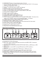
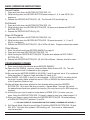
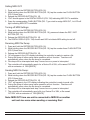
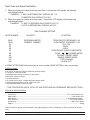
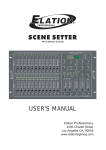
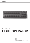
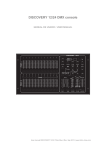
User Instructions
SCENE SETTER™
1
2
3
MIDI
CAPABLE
8
9
DMX-512
10 11 12 13 14 15 18 17
18
19
20
21
4
5
6
7
23 24
25 26 27 28 29 30
31
22
CONTROLS & FUNCTIONS
1. PRESET A LED’S: Will indicate the activity for sliders 1 - 12.
2. CHANNEL FADERS 1 - 12: Slide the faders to adjust the DMX output (from 0 to 255) or
fixture intensity (from 0% to 100%).
3. FLASH 1- 12: Press to momentary activate maximum channel output.
4. PRESET B LED’S: Will indicate the activity for sliders 13 - 24.
5. SCENE LED’S: When lit will indicate which scene or scenes are activated.
6. CHANNEL FADERS 13 -24: Slide the faders to adjust the DMX output (from 0 to 255) or
fixture intensity (from 0% to 100%).
7. FLASH 13 -24: Press to momentary activate maximum channel output.
8. DARK: Press to momentarily black out all output including FULL, FLASH and Programs.
9. DOWN / BEAT REV: The DOWN function is used to modify a scene in the EDIT MODE;
BEAT REV is used to reverse the chasing direction of a SCENE program with regular
beat.
10. MODE SELECT / REC SPEED: Press to select the desired operating mode CHASE
SCENE/ DOUBLE PRESET / SINGLE PRESET, the corresponding LED’S light up to indicate
function.
11.UP/CHASE REV: The UP function is used to modify a scene in the EDIT MODE; CHASE
REV is used to reverse the chasing direction of a SCENE program with speed control.
Specifications are subject to change without notice! - Scene Setter User Manual page 1
12. PAGE SELECT: Press to change between pages of scenes.
13. DELETE REV ONE: Press and hold this button then press any FLASH 13 -24 to reverse
direction of Scene that is running.
14. EXIT: Press to select ADD or KILL mode
15. INSERT / % OR 0-255: Press to select LCD DISPLAY
16. RECORD: Press to record output step by step.
17. EXIT / ALL REV: Press to reverse chasing direction of programs
18. PARK: In CHASE SCENE mode press to select SINGLE or MIX mode
19. HOLD: Press to maintain all output.
20. AUDIO: Press for MUSIC chase.
21. STEP: Press to step to next SCENE.
22. AUDIO LEVEL: Adjust sensitivity of AUDIO input
23. MASTER SLIDER A: Adjusts PRESET A output.
24. BLIND: Press to activate the BLIND function in CHASE SCENE MODE. This locks in the
values of the CHANNEL output until you press BLIND again. - Full Output.
25. HOME: Press to activate HOME in CHASE SCENE MODE this
26. MASTER SLIDER B: Adjusts PRESET B output.
27. TAP SYNC: In RUN MODE the interval of two taps determines the chase speed.
28. FADE: SLIDER. Move to adjust FADE TIME.
29. FULL-ON: Use to Max output of CHANNELS
30. SPEED: Move to adjust speed of chase
31. BLACK OUT: Turns off all functions and output.
Rear Panel Connections;
33
32
DC INPUT
34
37
36
35
DMX OUT
MIDI
1:GND
1
2
2:DATA 3:DATA +
-
1:GND
39
REMOTE
REMOTE
19
2:DATA +
3:DATA -
+
DC 12V-20V
500mA min.
38
1/4” STEREO JACK
LINE INPUT
THRU
OUT
IN
3
DMX POLARITY SELECT
100 mV - 1VP-P
FULL ON
BLACK OUT
GROUND
32. DC INPUT: DC 12-20v, 500 mA min.
33. MIDI THRU: Used to transmit MIDI data received from the MIDI IN (FIG. 4) connector
to a sperate MIDI component.
34. MIDI OUT: Used to transmit the SCENE SETTER’S MIDI DATA to a MIDI fixture or MIDI
power pack.
35. MIDI IN: Used to receive MIDI incoming MIDI data from a MIDI controller or
sequencer.
36. DMX OUT: Used to send DMX data to DMX Fixture or DMX power pack.
37. DMX POLARITY SELECTOR: Used to select DMX polarity output signal.
38. AUDIO INPUT: Enables the SCENE SETTER to run sound active, signal must range
39. REMOTE INPUT: BLACK OUT and FULL ON may be controlled by a remote using a
standard 1/4 stereo jack.
Specifications are subject to change without notice! - Scene Setter User Manual page 2
BASIC OPERATING INSTRUCTIONS
Record Enable
1. Press and hold down the RECORD BUTTON (FIG. 16)
2. While holding down the RECORD BUTTON press bumpers 1, 6, 6, and 8 (FIG. 3) in
sequence.
3. Release the RECORD BUTTON (FIG. 16) - The Record LED should light up.
Exit Record
1. Press and hold down the RECORD BUTTON (FIG. 16).
2. While holding down the RECORD BUTTON (FIG. 16) press and release the REC EXIT
BUTTON (FIG.14)
3. Release the RECORD BUTTON (Fig.16),
Erase All Programs
1. Press and hold down the RECORD BUTTON (FIG. 16).
2. While holding down the RECORD BUTTON (FIG. 16) press bumpers 1, 4, 2, and 3
(Fig.3), in sequence.
3. Release the RECORD BUTTON (FIG. 16) all LEDs will flash. Programs should be erased.
Clear Memory
1. Enter the record mode (see RECORD ENABLE on page 2).
2. Press and hold down RECORD BUTTON (FIG. 16).
3. While holding the RECORD BUTTON (FIG. 16) press and release the REC CLEAR
BUTTON (FIG. 12).
4. Release the RECORD BUTTON (FIG. 16), All LEDs will flash. Memory should be clear.
PROGRAMMING SCENES
1. Enter record mode (As describe above:RECORD ENABLE).
2a.Select the1-24 SINGLE mode by using the Mode Select button (FIG. 10). This will
give you control of all 24 channels as you program.
2b.Be sure that the MASTER FADERS A & B (FIGS. 2 and 3) are both set at 10 or maximum
(Note that slider ‘A’ starts at 0 and that slider ‘B’ starts at 10).
3a.Use FADERS 1-24 (FIGS. 2 and 3) to set intensities. At 0% or DMX 0, the fader should
be at the 0 position (fader at bottom) and at 100% or DMX255 the fader should be
at the10 position (Fader at top).
3b.After all faders have been adjusted to their desired setting press the RECORD
BUTTON (FIG. 16) to send this step to memory. Repeat steps 1 through 3b until all
the desired steps have been placed into memory (You may record up to 4200 steps into
memory).
3c. At this point you need to select a chase bank or SCENE (FIG. 7) to store your program. Using the PAGE BUTTON (FIG. 12) select a page to store your chase (pages 1-4 .
To store your chase or scene hold down the RECORD BUTTON (FIG. 16) while pressing
a FLASH BUTTON (FIG.7) between 13 and 24.
**** YOU MAY STORE UP TO 48 SCENES ON FOUR PAGES (12 SCENES PER A PAGE)****
4. Exit Record Mode: (See Exit record Page 2) Hold the RECORD BUTTON (FIG. 16) and
KILL (FIG. 14) button then release. LED should go off. Your scene or chase should
now be recorded.
©Elation Professional® Los Angeles, CA 90058 -Scene Setter User Manual page 3
RUNNING SCENES
1. After all your programming is complete, you may run your program.
2. Using the MODE SELECT BUTTON (FIG. 10) select ‘CHNS SCENES’.
3. Turn the slider, for the appropriate flash button the scene was recorded, to the
maximum or 10 position. The yellow scene LED should light and all green LED’S for the
corresponding sliders that were programmed into that scene.
DELETE PROGRAM
1. Enter the record mode (SEE RECORD ENABLE ON PAGE 2).
2. Use the PAGE BUTTON (FIG. 12) to selected the page the program you wish to delete is
on.
3. Press and hold the RECORD BUTTON (FIG. 16).
4. While holding down the RECORD BUTTON (FIG. 16) press the appropriate FLASH BUTTON
(FIG.7), that stores the program your deleting, twice.
5. Release the RECORD BUTTON (FIG. 16). All LED’S will flash signaling the program was
deleted.
EDITING PROGRAMS
1. Enter the record mode (SEE RECORD ENABLE ON PAGE 2).
2. Use the PAGE BUTTON (FIG. 12) to selected the page the program you wish to delete
is on.
3. Using the MODE SELECT BUTTON (FIG. 10) select ‘CHNS SCENES.’
4. Press and hold the EDIT BUTTON (FIG. 17).
5. While holding down the EDIT BUTTON (FIG. 17) press the FLASH BUTTON (FIG. 7) that
corresponds to the program you wish to edit.
6. Release the EDIT BUTTON (FIG. 17), the relevant scene led should light indicating your in
the edit mode.
Delete Step:
1. Press the DELETE BUTTON (FIG. 13) when you reach the step you wish to delete.
2. All LED’S will flash briefly to indicated the steps deletion.
3. Continue steps 2 and 3 until all the unwanted scenes have been deleted.
Adding Steps:
1. Enter the EDIT MODE as described above.
2. Use the STEP BUTTON (FIG. 21) to bump your way through the scenes to reach the
step after the scene you wish to insert.
3. Create the step you wish to insert as described on page 2 ‘PROGRAMMING SCENES.’
4. Press the INSERT BUTTON (FIG. 15) when you reach the step you wish to delete.
5. All LED’S will flash briefly to indicated the steps deletion.
6. Continue steps 2, 3, and 4 until all the desired scenes have been added.
Modify Steps:
1. Enter the EDIT MODE as described on above.
2. Use the STEP BUTTON (FIG. 21) to bump your way through the program until you
reach the step you wish to modify.
3. Press and hold either the UP OR DOWN BUTTONS (FIGS. 9 & 10) and the desired FLASH
BUTTON (FIGS. 3 & 7) that corresponds to the fixture you wish modify, until you reach
the desired output reading in the DIGITAL DISPLAY (FIG. 13A).
©Elation Professional® Los Angeles, CA 90058 -Scene Setter User Manual page 4
4. Continue steps 2, 3, and 4 until all the desired steps have been modified.
Exit Edit Mode:
1. Press and hold the RECORD BUTTON (FIG. 16).
2. While Holding down the RECORD BUTTON (FIG. 16) press and release the REC EXIT BUTTON
(FIG. 14).
3. Release the RECORD BUTTON (FIG. 16).
SELECT AND RUNNING PROGRAMS
Running programs:
1. To run a program; press the MODE SELECT BUTTON (FIG. 10) and select ‘CHNS
SCENES,’ this will be indicated by a red led.
2. Press the PAGE BUTTON (FIG. 12) to select the correct page (1-4) the program youwish to
run is located.
3. Be sure your MASTER A (FIG. 23) and MASTER B (FIG. 26) faders are in the 10 position
(maximum). Note: The 10 position is opposite for MASTER A (FIG. 23) and MASTER B
(FIG.26) fader.
4. Move the desired SCENE CHANNEL SLIDER (FIG. 6) to its maximum position to trigger
the scene, the YELLOW LED (FIG. 5) should light noting scene selection. Note: If the
desired channel slider is al;ready in it raised position and the program does not start,
lower the slider to its minimum level and raise it back to its maximum level to engage
the program!
Running A Program To Audio:
1. Be sure an audio source is plugged into the RCA AUDIO JACK (FIG. 38) in the rear of
the unit.
2. Select your program as described above.
3. Press the AUDIO BUTTON (FIG. 20), its green led should light indicating its selection.
4. Use the AUDIO LEVEL CONTROLLER SLIDER (FIG. 22) to just the music sensitivity.
5. To return to normal operating mode deselect the AUDIO BUTTON (FIG. 20) to disengage
audio mode.
Running A Program With A Standard Beat:
1. Be sure the audio is disengaged. The AUDIO BUTTON (FIG. 20), green led should be
turned off. The MODE SELECT BUTTON (FIG.10) must be in ‘CHNS
SCENES’ to
control the audio mode.
2. Press the MODE SELECT BUTTON (FIG.10) and select ‘CHNS
SCENES.’
3. Press the PARK BUTTON (FIG. 18) to select MIX CHASE MODE. A yellow LED will indicate this
selection.
4. Select your program as described above.
5. Move the SPEED SLIDER (FIG. 11) to your desired speed adjustment, or tap the TAP SYNC
BUTTON (FIG. 15) twice to define your beat time.
6. Press and hold the REC SPEED BUTTON (FIG .25) and the FLASH BUTTON (FIG. 7) that stores
the program you wish to apply the beat time to.
7. Repeat steps 4 and 5 until you have applied time to all your desired programs.
8. The program(s) will then run with the set time or beat when they are engaged.
©Elation Professional® Los Angeles, CA 90058 -Scene Setter User Manual page 5
Running A Program With The Speed Slider:
1. Be sure the audio is disengaged. The AUDIO BUTTON (FIG. 20), green led should be
turned off. The MODE SELECT BUTTON (FIG.10) must be in ‘CHNS
SCENES’ to
controll the audio mode.
2. Press the MODE SELECT BUTTON (FIG.10) and select ‘CHNS
SCENES.’
3. Press the PARK BUTTON (FIG. 18) to select MIX CHASE MODE. A yellow LED will indicate this
selection.
4. Select your program as described on page 5.
5. Slide the SPEED SLIDER (FIG. 11) to the SHOW MODE position (The Bottom).
6. Press and hold the REC SPEED BUTTON (FIG. 25) and the FLASH BUTTON (FIG. 7) that stores
the program you wish to apply the beat time to. Release both buttons.
7. Repeat steps 4 and 5 until you have applied time to all your desired programs.
8. The program(s) will then run controlled by the speed slider.
9. Run your program.
10. As you run your program move the SPEED SLIDER (FIG. 30) until 0.10 (Top) appears in the
LCD display the program will run with 10 steps per a second. 3.00 will give you 1 step per
a second, 5.00 will give a step every three second, etc.
SPEED SETTING
Setting To 5 Minute Operating Mode:
1. In any mode press and hold the RECORD BUTTON (FIG. 16).
2. While holding down the RECORD BUTTON (FIG. 16), tap the number 5 FLASH BUTTON
(FIG. 3) three time.
3. Release the RECORD BUTTON (FIG. 16).
4. The 5 MIN LED show light up indicating the speed slider is set to run in the 5 minute mode.
Setting To 10 Minute Operating Mode:
1. In any mode press and hold the RECORD BUTTON (FIG. 16).
2. While holding down the RECORD BUTTON (FIG. 16), tap the number 10 FLASH BUTTON
(FIG. 3) three time.
3. Release the RECORD BUTTON (FIG. 16).
4. The 10 MIN LED show light up indicating the speed slider is set to run in the 10 minute mode.
ENABLING MIDI OPERATION
Setting MIDI IN:
1. Press and hold the RECORD BUTTON (FIG. 16).
2. While holding down the RECORD BUTTON (FIG. 16), tap the number one (1) FLASH
BUTTON (FIG. 3) three time.
3. Release the RECORD BUTTON (FIG. 16).
4. ‘ChI’ should appear in the LCD display indicating MIDI IN is available.
5. Press the corresponding FLASH BUTTON (FIG. 7) to assign ‘MIDI IN’ to your desired program
its LED will light indicating ‘MIDI IN’ is set.
©Elation Professional® Los Angeles, CA 90058 -Scene Setter User Manual page 6
Setting MIDI OUT:
1. Press and hold the RECORD BUTTON (FIG. 16).
2. While holding down the RECORD BUTTON (FIG. 16), tap the number two FLASH BUTTON
(FIG. 3) three time.
3. Release the RECORD BUTTON (FIG. 16).
4. ‘Ch0’ should appear in the DIGITAL DISPLAY (FIG. 13A) indicating MIDI OUT is available.
5. Press the corresponding FLASH BUTTON (FIG. 7) you wish to assign MIDI OUT, its LED will
light indicating MIDI OUT is available.
Turning off MIDI Settings:
1. Press and hold the RECORD BUTTON (FIG. 16).
2. While holding down the RECORD BUTTON (FIG. 16), press and release the REC / EXIT
BUTTON (FIG. 14).
3. Release the RECORD BUTTON (FIG. 16).
4. The DIGITAL DISPLAY (FIG. 13A) should read 0.00 to indicate MIDI setting turned off.
Receiving MIDI File Dump:
1. Press and hold the RECORD BUTTON (FIG. 16).
2. While holding down the RECORD BUTTON (FIG. 16), tap the number three FLASH BUTTON
(FIG. 3) three time.
3. Release the RECORD BUTTON (FIG. 16).
4. ‘IN’ will appear in the LCD display indicating the controller is ready to receive a file
5. During file dump all other scene setter operation will not function. Functions will
automatically return when the file dump is completed.
6. File dump will be interrupted and stop if errors occur or power is interrupted.
7. The controller will automatically search for a Device ID of 55H, a file named ‘DC1224‘
with an extension of ‘BIN [SPACE].’
Sending MIDI File Dump:
1. Press and hold the RECORD BUTTON (FIG. 16).
2. While holding down the RECORD BUTTON (FIG. 16), tap the number four FLASH BUTTON
(FIG. 3) three time.
3. Release the RECORD BUTTON (FIG. 16).
4. ‘OUT’ will appear in the LCD display indicating the controller is ready to send a file
5. During file dump all other scene setter operation will not function. Functions will
automatically return when the file dump is completed.
6. File dump will be interrupted and stop if errors occur or power is interrupted.
7. The controller will automatically send a file to a Device ID of 55H, a file named
‘DC1224‘ with an extension of ‘BIN [SPACE].’
Note: MIDI OUT from one unit is connected to MIDI IN on another
unit and vice verse when sending or receiving files!
©Elation Professional® Los Angeles, CA 90058 -Scene Setter User Manual page 7
FUNCTIONS:
Fade Time:
1. The amount of time it will take for the dimmer to go from zero output to maximum output
or the amount of time it will take for the DMX signal to go from zero to 255, and vice
verse.
2. Fade time is adjusted through the FADE SLIDER (FIG. 28), which varies from instant to 10
minutes.
SINGLE MODE (FIG.18):
1.
2.
3.
4.
All programs will run in sequential order starting with program one.
The DIGITAL DISPLAY (FIG. 13A) will display the running program number.
All programs will be controlled by the same SLIDER SPEED (FIG. 30).
Be sure the audio is disengaged. The AUDIO BUTTON (FIG. 20), green led should be
turned off. The MODE SELECT BUTTON (FIG.10) must be in ‘CHNS
SCENES’ to
controll the audio mode.
5. Press the MODE SELECT BUTTON (FIG.10) and select ‘CHNS
SCENES.’
6. Press the PARK BUTTON (FIG. 18) to select SINGLE CHASE MODE. A red LED will indicate
this selection.
Mix Mode
1. Will run all programs synchronously
2. All programs can be controlled by the same SLIDER SPEED (FIG. 30), or each
programs speed may be controlled individually (See speed settings page 6).
3. Be sure the audio is disengaged. The AUDIO BUTTON (FIG. 20), green led should be
turned off. The MODE SELECT BUTTON (FIG.10) must be in ‘CHNS
SCENES’ to
controll the audio mode.
4. Press the MODE SELECT BUTTON (FIG.10) and select ‘CHNS
SCENES.’
5. Press the PARK BUTTON (FIG. 18) to select MIX CHASE MODE. A yellow LED will indicate this
selection.
Display:
1. The 3-DIGIT DIGITAL DISPLAY (FIG. 13A) is designed to display fader percentage or
DMX values.
2. To change between percentage and DMX value: Press and hold the RECORD
BUTTON (FIG. 16). While holding down the record button press the INSERT / % OR 2-255
BUTTON (FIG. 15) to switch between percentage and DMX values.
Blind:
1. This function takes channels temporally out from a chase, when the chase is
running, and gives you manual control over the channel.
2. Press and hold the BLIND BUTTON (FIG. 24) and Tap the FLASH BUTTON (FIG. 7) of
channels you want to temporarily take out of chase.
3. To return to normal chase again press and hold the HOME BUTTON (FIG. 25) and push the
FLASH BUTTON (FIG.7) to the channels you want to return to normal chase.
©Elation Professional® Los Angeles, CA 90058 - Scene Setter User Manual page 8
Fade Time and Speed Indicators:
1. When a program is running at a time more than 1 minute the LCD display will indicate
two decimal points:
EXAMPLE: 1 AND 15 SECONDS WILL DISPLAY AS 1.15
10 MINUTES WILL DISPLAY AS 10.0
2. When a program is running at a time under 1 minute the LCD display will indicate only
one decimal points:
EXAMPLE: 11 AND 1/2 SECONDS WILL DISPLAY AS 11.5
1/10 OF A SECOND WILL DISPLAY AS 0.10
MIDI CHANNEL SETTING
NOTE NUMBER
22-69
70-93
94
95
96
97
98
99
100
101
102
VELOCITY
PROGRAM MASTER
CHANNEL DIMMER
FUNCTION
TURN ON/OFF PROGRAMS 1-48
TURN ON/OFF CHANNELS 1-24
FULL ON
DARK
HOLD
TURN ON/OFF AUDIO CHASE MODE
CHNS
SCENES MODE
DOUBLE PRESET MODE
SINGLE PRESET MODE
STEP CHANGE
BLACK OUT
A SCENE SETTERS MIDI Information may be sent to another SCENE SETTER for back up purposes
SPECIFICATIONS
•
•
•
•
•
•
•
•
All scenes, chases and options retained by backup battery
5 space 19” rack mount case
Reversible DMX polarity via switch on rear panel
MIDI input, output, and thru
24 DMX Channels
12 program per a page- 4 pages total (48 programs total)
Scenes triggered by sound, time, MIDI or tap sync.
Comprehensive MIDI control functions
THIS CONTROLLER HAS A TOTAL OF 4200 STEPS AND 48 PROGRAMS. MIDI IN/OUT/THRU
TECHNICAL SPECIFICATIONS:
Power Input..............................................................................................................................DC 12-20V, 500mA min.
DMX Output........................................................................................................................................3 pin Female XLR
MIDI Signal.............................................................................................................................5 pin Standard Interface
Fuse (Internal).................................................................................................................................F 0.5 250V 5x20mm
Dimensions.........................................................................................................................................482 x 264 x 85mm
Weight.....................................................................................................................................................................3.6Kg
Note; A low input voltage will be indicated in the digital display as LOP - During start up LOP may show up momentarily.
©Elation Professional® Los Angeles, CA 90058 -Scene Setter User Manual page 9