1
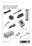
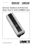
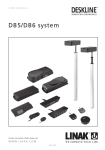
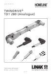
USER MANUAL
5 th Driving wheel
To learn more about LINAK please visit:
W W W. L I N A K . C O M
Page 1 of 24
Page 2 of 24
Contents
Preface ......................................................................................................................................................
4
Important information ..............................................................................................................................
5
The 5th Driving wheel system consists of the following products .........................................................
5
System diagram .........................................................................................................................................
6
Connection of the 5th Driving wheel (CB16) ............................................................................................
7
th
Connection of the 5 Driving wheel (CB20) ............................................................................................
8
Connection of the 5th Driving wheel (CB6S) ............................................................................................
9
Explanation ................................................................................................................................................ 10
Trooubleshooting / Instruction ................................................................................................................. 11
5th Driving wheel - Control Unit ............................................................................................................... 12
5th Driving wheel - Battery ....................................................................................................................... 14
5th Driving wheel - Control handset ........................................................................................................ 15
Key to symbols ........................................................................................................................................... 16
Labels
...................................................................................................................................................... 17
Drawing appendix ..................................................................................................................................... 18
Declaration of confirmity .......................................................................................................................... 22
Addresses ................................................................................................................................................... 24
Page 3 of 24
Preface
We are delighted that you have chosen a product from LINAK®.
LINAK systems are high-tech products based on many years of experience in the manufacture and
development of actuators, electric control boxes, controls and chargers.
This User Manual will tell you how to install, use and maintain your LINAK equipment.
We are sure that your LINAK system will give you many years of problem-free operation. Before our products
leave the factory they undergo full function and quality testing. Should you nevertheless experience problems
with your systems, you are always welcome to contact your local dealer.
LINAK subsidiaries and some distributors situated all over the world have authorised service centres, which
are always ready to help you.
LINAK provides a warranty on all its products. This warranty, however, is subject to correct use in accordance
with the specifications, maintenance being done correctly and any repairs being carried out at a service
centre, which is authorised to repair LINAK products.
Changes in installation and use of LINAK systems can affect their operation and durability. The products are
not to be opened by unauthorised personnel. The User Manual has been written on the basis of our present
technical knowledge. We are constantly working on updating the information and we therefore reserve the
right to carry out technical modifications.
LINAK A/S
Page 4 of 24
Important information
For further information regarding Warnings and Recommandations,
please read the user manual Actuators and Electronics on our website
www.linak.com.
The 5th Driving wheel system consists of the following products.
Driving wheel (see page 7):
• in partnership with TENTE (Driving wheel must be ordered from Tente)
Control Unit (see page 12):
• CUDM
• Compatible with CB16, CB20 and CB6S control boxes and LINAK controls
Battery (see page 14):
• BADM 2.9 Ah
Control handset (see page 15):
• Special handset
• Special activation key
• Compatible with CB16, CB20 and CB6S control boxes
Usage:
• Compatibility:
• Duty cycle:
• Usage temperature:
• Relative humidity:
• Storage temperature:
• Atmospheric pressure:
• Approvals:
CB16, CB20 and CB6S (longer charging time)
Continuous use (on fully charged battery)
5ºC to 40ºC
20% to 80% at 30ºC
-10ºC to 50ºC
700 to 1060 hPa
Pending
Page 5 of 24
System diagram
J90000, HBDM
To existing CB20 / CB16 / CB6S system.
• CB20 with channel 7 option
• CB16 with channel “X” option
• CB6S with MJB
0858008, Magnet
CUDM00000A01062
BADM16-0100-0000
0964526-2000
0964525-280
0964519-1500
Do not use spare OpenBus™ ports on CUDM for other purposes, insert “blind plugs”.
Assembly procedure:
Must be followed in order to secure no potential power errors
• No mains connected!
• Mount cable on the wheel
• Mount wheel cable in CUDM yellow ring to the left side (ch.1), green to the right side (ch.2) as shown on
next pages
• Mount CUDM battery cable
• Connect CUDM to power from CU20, channel 7
• Connect HBDM to existing OpenBus™ system
• Connect to mains and charge to 100%
Page 6 of 24
Connection of the 5th Driving wheel (CB16)
Important: Connections of the components in the wrong sequence may damage the equipment.
Please follow the instructions strictly. As the system is powered by battery it can be unintentionally
powered up and create hot-plugging!
STEP 1.
STEP 2.
Make sure that the CB16 is NOT connected to mains.
Connect cable 0964519 to the wheel, see below.
STEP 3.
Connect cable 0964519 to the CUDM. The connector with yellow O-ring in port “Out 1” and the
connector with green O-ring in port “Out 2”.
BADM
Cable connects
to CB16
CUDM
1
2
3
STEP 4.
STEP 5.
Connect cable 0964525 between BADM and CUDM port “Out 3”.
Connect cable 0964526 to CUDM port “In1” and CB16 port “6”.
CB16
6
Cable connects
to CUDM
STEP 6.
STEP 7.
STEP 8.
STEP 9.
Connect HBDM to CB16 “A”.
Connect mains cable.
Insert blind plugs in unused CUDM connector ports, and fasten cable locks on CUDM and CB16.
Before use, charge the system for at least 1 hour.
Page 7 of 24
Connection of the 5th Driving wheel (CB20)
Important: Connections of the components in the wrong sequence may damage the equipment.
Please follow the instruction strictly.
1. Make sure that the CB20 is NOT connected to mains.
2. Connect cable 0964519 to the wheel.
3. Connect cable 0964519 to the CUDM. The connector with yellow O-ring in port “Out 1” and the
connector with green O-ring in port “Out 2”.
BADM
CUDM
1
2
3
4. Connect cable 0964525 between BADM and CUDM port “Out 3”.
5. Connect cable 0964526 to CUDM port “In1” and CU20 port “Out 7”.
CB20
7
6.
7.
8.
9.
Connect HBDM to CU20 “In 1”.
Connect mains cable.
Insert blind plugs in unused connectors, and “click” cable locks on CUDM and CB20.
Before use, charge the system for at least 1 hour.
Page 8 of 24
Connection of the 5th Driving wheel (CB6S)
Important: Connection of the components in the wrong sequence may damage the equipment.
Please follow the instructions strictly.
If CB6S is used, the charging will take place via the normal OpenBus™ connection. a standard cable W.RO45
(6 wires modular Jack) with plugs in both ends is connected to CB6S via a MJB.
Follow steps 1 to 4 in the previous descriptions.
Disconnection of the 5th Driving wheel
1. If not connected to mains, connect the system to mains, for at least 10 seconds.
2. Disconnect mains and remove mains cable. Wait at least 30 seconds.
3. Remove cable between CUDM and CU20.
4. Disconnect HBDM.
5. Remove cable between wheel and CUDM.
6. Remove cable between Battery and CUDM.
Connection of IB30/service tool
Important: Connection of the components in the wrong sequence may damage the equipment.
Please follow the instructions strictly.
1.
2.
3.
4.
5.
If not connected to mains, connect the system to mains, for at least 10 seconds.
Disconnect mains, and wait at least 30 seconds.
Connect the IB30 to CU20 port “In 2”.
Connect to mains.
Connect the IB30 to the PC (USB cable)
Disconnection of IB30/service tool
Important: Disconnection of the components in the wrong sequence may damage the equipment.
Please follow the instructions strictly.
1. Remove the USB cable from the PC and IB30.
2. Disconnect the IB30 from CU20 port “In 2”.
Page 9 of 24
Explanation:
Battery level:
When the bed is connected to mains the battery indicators will be lit.
When the batteries are fully charged all 3 battery indicators will be lit,
(in cases where the 25% indicator is lit the bed should be charged). As
the batteries are being discharged the indicators will gradually turn off.
Arrow Up: Drive Forward
Arrow Down: Drive backwards
Hare: Drive fast. When this function is chosen it’s indicator will be lit.
Turtle: Drive slow. The system is set up in such a way, that it always
starts driving slowly. The turtle indicator will therefore always be lit at
start up.
Activation button: For activation of the panel, touch the raised area
lowest on the handset with the magnet shown in the photo below.
It is recommended to test the Drive Me system before driving with a patient.
INSTRUCTIONS:
1. Activate panel with magnet. LED above Turtle will illuminate.
2. Choose other speed if desired.
3. Activate by the use of arrow buttons for desired driving direction.
4. After the transportation is completed the bed must be connected to mains for battery charging.
Be aware of:
1. Wheel lowers automatically and starts driving at once, when an arrow button is activated (only if the
panel has been activated).
2. Wheel raises automatically approx. 5 seconds after end of driving.
3. The panel will be active for approx. 10 seconds after the wheel has been raised, after which all indicators
will turn off.
4. During connection of mains the panel cannot be activated and drive functions are therefore not available.
5. Do not move the bed from side to side before the wheel has been raised from the floor.
Page 10 of 24
Troubleshooting / Instruction.
ERROR MODE
LED signal
Trigger
Error Mode
Do the following
The two speed LEDs flashing
at fast flashing rate for 3
seconds
Activation of Enable by Magnet™
sensor when connected to mains
Drive lockout
Remove connection from mains and retry
The two speed LEDs flashing
at fast flashing rate
Activation of both direction keys
HBDM Key Error
Wait until EBM* is disabled. If error is not
removed then check HBDM keys.
The two speed LEDs flashing
at slow flashing rate
HBDM keeps Enable by Magnet™
active for longer than Enable by
Magnet time out + 5
HBDM Enable by Magnet™
Timer Error
Wait until EBM* is disabled. If error is not
removed then check HBDM.
All three battery indicators
flashing: 25% and 100% at
slow flashing rate, 50% at
fast flashing rate
Charger has detected overload
condition
Stopped, Overload (not
charging)
Disconnect mains, check battery connections.
Connect to mains until charged.
VPermanent has been lower than
34V for more than 30 seconds
Stopped, Low VPermanent
(not charging)
Remove load. Stop movements of application.
Reconnect mains.
All three battery indicators
flashing at slow flashing rate
Mains not detected (mains bit not
active for 10 frames in a row)
Stopped, Mains not detected
(not charging)
Remove mains, wait 10 sec. and reconnect.
Buzzer signal
Trigger
Error Mode
Do the following
One short beep
When any key is activated while on
battery and Enable by Magnet™
is not active.
Locked mode
1.Enable EBM and retry
2.Return CUDM to LINAK for service
Failure on system to power down
Power Down Error
Three short beeps
Battery Capacity less than 25%
when the wheel is raised
Low Battery
Warning signal for low battery: Connect to
mains until fully charged
One long beep
If the Power Switch Error bit in the
Error Register is set, one long beep
sounds every time the user activates
a direction key
Power Switch Error
Connect to mains, and disconnect. Try again.
If problem persists, return CUDM to LINAK
Five long beeps
Temperature, FET exceeds FET
Temperature Limit
FET Temperature Exceeded
Return item to LINAK
Three long beeps
The wheel connected input is short
circuited
Wheel failure
Wheel Up Switch failed to:
Wheel Up Switch failure
1. Check all connections are in place
2. Exchange wheel cable and / or wheel
3. Exchange CUDM
The CUDM has detected low
battery state
No further running allowed
*EBM means Enable by Magnet
Wheel goes down and
immediately up again
Charge battery (Connect to mains)
Information regarding resetting the HBDM in case it is already configured to another CUDM.
1. S1 & S2, 10 seconds including mains on.
Hereafter mains off wait 5 seconds, mains on again 10 seconds; hereafter OK (this is called a power cycle.
2. S3 + S4, 10 sec. LED flashes, release button => HB + 2. uP er.
Reset of configuration, e.g. if HBDM has been exchanged:
a) Make sure the system is powered from mains.
b) Press and keep pressed both the Hare and the Turtle keys (S3 and S4) until all LEDs start flashing at a fast
rate (will happen after 10 seconds).
c) Release the keys and the CUDM will reconfigure all system components.
d) When configuration is done, the LEDs will stop flashing and return to showing the level of battery charge.
e) Disconnect mains. System is ready for use.
Page 11 of 24
5th Driving wheel - Control Unit
CUDM is the Control Unit for the Driving Wheel system. This is where communication between the battery,
handset and wheel takes place.
The Control unit comprises of two channels for controlling motors. One channel (CH1) is dedicated to the
Wheel Motor and the other (CH2) is dedicated to the Wheel Lowering Motor.
CUDM includes:
1 pcs.
0770021-A Microfit Blind Plug
2 pcs.
0770022-A Minifit Blind Plug
1 pcs.
0951027-A Retainer
Features and Options:
• Softstart and softstop:
• Colour:
• Plug type:
• Charging:
• Power supply:
Yes
Light grey RAL7035
OpenBus™ plug (Battery input ch.3, rotated 180º)
via OpenBus™
BADM Battery box
Usage:
• Compatibility:
• Duty cycle:
• Duty cycle:
•
•
•
•
•
CB20, CB16OBF, CB16OBL, CB6OBF and CB6OBM
Driving motor continuous
Wheel lowering motor 2/18; 2 minutes continuous use
followed by 18 min. not in use
Usage temperature:
5ºC to 40ºC
Storage temperature:
-10ºC to 50ºC
Relative humidity: 20% to 80% at 30ºC
Atmospheric pressure:
700 to 1060 hPa
Approvals:
Pending
Page 12 of 24
Battery indicators:
Management of HBDM Battery Charge State LED’s.
The HBDM battery charge state LED’s are controlled as follows:
Battery
percentage
remaining
LED
25 %
50 %
100 %
0 - 10 %
Flashing fast
Off
Off
10 - 40 %
Lit
Off
Off
Silent
40 - 80 %
Lit
Lit
Off
Silent
80 - 100 %
Lit
Lit
Lit
Silent
Buzzer
According to Table 2 (see later page)
when the wheel is raised.
Charging:
This is valid when charging (mains) or while being activated. If disconnected from mains and no activation all
LED’s are off.
Speed LEDs
When the 5th Driving wheel system is powered from battery, the HBDM speed LEDs show the selected speed.
Configuration:
All software for the entire system is Quality Test released. There will not be a Software task. However there
might be a configuration task, depending on the existing system software.
In case of a configuration, a template must be filled out and added to ‘Further Specification’ in the ‘System
Specification’ for the CUDM. The Template can be found on LINTRA.
If the addresses shown in the following are already in use in the existing system (software), where 5th Driving
Wheel is to be used, then a configuration is necessary. In this case the CUDM must be created as a special
item.
If OpenBus™ addresses can be used as shown in the following explanation, no further software/configuration
is necessary.
Standard Configuration:
These addresses must be checked to see if they are used by an existing
system. Check the CU/CB software specification. If these addresses are in
use, a new configuration must be described.
S1 is defined as driving forward direction. Standard address is H22
S2 is defined as driving backwards. Standard address is H23
S3, Turtle is defined as driving slowly. Standard address is H24
S4, Rabbit is defined as driving fast. Standard address is H25
Page 13 of 24
5th Driving wheel - Battery
The battery supplies power to the CUDM. The battery charge state is monitored in the CUDM and is
displayed in the handset (HBDM).
Features and Options:
• Battery capacity:
• Input voltage:
• Capacity monitoring:
• Colour:
• Plug type:
• Charging:
• Power supply:
• IP rating:
2.9 Ah
24 V
via handset or Service data
Light grey RAL7035
Mini-fit (turned 80º)
via CUDM
no external power supply available
IPx6
Usage:
• Compatibility:
• Duty cycle:
• Usage temperature:
• Relative humidity:
• Storage temperature:
• Atmospheric pressure:
• Approvals:
• Internal fuse:
CUDM only
Continuous use
5ºC to 40ºC
205 to 80% at 30ºC
-10ºC to 50ºC
700 to 1060 hPa
Pending
10A
Charging time via an MJB (CB6OBM/CB6OBF) > 25 hours
Charging time via CB16 / CB20 approx. 8 hours
Only to be charged via CUDM
Page 14 of 24
5th Driving wheel - Control handset
The handset is specially designed for control of the 5th Driving wheel. It is an intuitive handset which is easy to
use, the handset has arrow heads for moving forward or backwards.
To control the speed of the 5th Drive wheel it is only necessary to press one button. If the “rabbit” button is
pressed the system will go into fast mode, if the “turtle” button is pressed the system will drive at a lower
speed, which is suitable for maneuvering the bed in small places or around sharp and difficult corners.
Features and Options:
• max. 4 buttons
• max. 5 LED’s
• Customised design
• Colour
• Integrated
• IP rating
possible
light grey RAL7035
cable with OpenBus™ plug
IPx6
Usage:
• Compatibility:
• Duty cycle:
• Usage temperature:
• Relative humidity:
• Storage temperature:
• Atmospheric pressure:
• Approvals:
CUDM 5. Drive wheel system
Continuous use
5ºC to 40ºC
205 to 80% at 30ºC
-10ºC to 50ºC
700 to 1060 hPa
Pending
Functional description
The operating surface consists of 4 keys, 5 LED’s and a
hidden magnet activation key.
Keys:
Arrow pointing upwards: Drive forward
Arrow pointing downwards: Drive backwards
Hare: Fast speed
Tortoise: Low speed
Magnet activation:
Must be activated in order to use the system
LED’s:
25%, 50%, 100%: Indicates battery capacity
Hare: LED lit when fast speed chosen
Tortoise: LED lit when slow speed chosen
Page 15 of 24
Key to symbols
The following symbols are used on the label on the LINAK products.
Demko approval
UL file number
Fimko approval
UL file number
UL file number
CSA
Australian approval mark
PSE-Mark
Australian approval mark
Recognised - Component Mark
Product with a thermofuse
Canadian
Recognised - Component Mark
For indoor use (House).
Recognised
Component Mark for Canada
and the United States
Safety isolating transformer.
T-Mark
Electronics scrap
RW-Tüv approval
Tüv.Produkt Service
Equipment Kl.2 (Double square)
TÜVRheinland
Patient part of type B (Mand)
Patient part of type BF
Earth protection
Equipment class1.
ETL
Earth
C-ETL
CE Mark
LGA
C-TICK
Page 16 of 24
Labels for 5th Driving wheel
Page 17 of 24
DRAWING APPENDIX
5th Driving wheel
Control
Unit
CUDM
Page 18 of 24
Battery
BADM
5th Driving wheel - Control Unit
Page 19 of 24
5th Driving wheel - Battery
Page 20 of 24
5th Driving wheel - Control handset
Page 21 of 24
Page 22 of 24
LINAK APPLICATION POLICY
The purpose of the application policy is to define areas of responsibilities in relation to applying a LINAK
product defined as hardware, software, technical advice, etc. related to an existing or new customer
application.
LINAK products as defined above are applicable for a wide range of applications within the Care and Health,
Comfort furniture, Desk and Industry areas. Yet, LINAK cannot know all the conditions under which LINAK
products will be installed, used, and operated, as each individual application is unique.
The suitability and functionality of the LINAK product and its performance under varying conditions
(application, vibration, load, humidity, temperature, frequency, etc.) can only be verified by testing, and shall
ultimately be the responsibility of the LINAK customer using any LINAK product.
It is also the responsibility of the LINAK customer to make and supply a comprehensive user manual of the
application.
LINAK shall be responsible solely that the LINAK products comply with the specifications set out by LINAK and
it shall be the responsibility of the LINAK customer to ensure that the specific LINAK product can be used for
the application in question.
Page 23 of 24
FACTORIES
CHINA
DENMARK
SLOVAKIA
USA
LINAK (Shenzhen) Actuator Systems, Ltd.
Phone: +86 75 58 61 06 656
Fax:
+86 75 58 61 06 990
E-mail: [email protected]
www.linak.cn
LINAK A/S - Group Headquarters Guderup
Phone: +45 73 15 15 15
Fax:
+45 74 45 80 48
Fax (Sales): +45 73 15 16 13
E-mail: [email protected]
www.linak.com
LINAK Slovakia s.r.o.
Phone: +421 51 75 63 414
Fax:
+421 51 75 63 410
E-mail: [email protected]
www.linak.com
LINAK U.S. Inc.
North and South American Headquarters
Phone: +1 50 22 53 55 95
Fax:
+1 50 22 53 55 96
E-mail: [email protected]
www.linak-us.com
AUSTRALIA
DENMARK
ITALY
POLAND
TAIWAN
LINAK Australia Pty. Ltd
Phone: +61 38 79 69 777
Fax:
+61 38 79 69 778
E-mail: [email protected]
www.linak.com.au
LINAK Danmark A/S
Phone: +45 86 80 36 11
Fax:
+45 86 82 90 51
E-mail: [email protected]
www.linak.dk
LINAK Italia S.r.l.
Phone: +39 02 48 46 33 66
Fax:
+39 02 48 46 82 52
E-mail: [email protected]
www.linak.it
LINAK Polska
Phone: +48 (22) 500 28 74
Fax:
+48 (22) 500 28 75
E-mail: [email protected]
www.linak.pl
LINAK A/S Taiwan Representative Office
Phone: +886 22 72 90 068
Fax:
+886 22 72 90 096
E-mail: [email protected]
www.linak.com.tw
AUSTRIA
FINLAND
JAPAN
REPUBLIC OF KOREA
TURKEY
LINAK Repräsentanz Österreich (Wien)
Phone: +43 (1) 890 74 46
Fax:
+43 (1) 890 74 46 15
E-mail: [email protected]
www.linak.at
LINAK OY
Phone: +358 10 84 18 700
Fax:
+358 10 84 18 729
E-mail: [email protected]
www.linak.fi
LINAK K.K.
Phone: +81 45 53 30 802
Fax:
+81 45 53 30 803
E-mail: [email protected]
www.linak.jp
LINAK Korea Ltd.
Phone: +82 (0) 2 6231 1515
Fax:
+82 (0) 2 6231 1516
E-mail: [email protected]
www.linak.kr
LINAK Ith. Ihr. San. ve Tic. A.S.
Phone: + 90 31 24 72 63 38
Fax:
+ 90 31 24 72 66 35
E-mail: [email protected]
www.linak.com.tr
BELGIUM & LUXEMBOURG
FRANCE
MALAYSIA
RUSSIAN FEDERATION
UNITED KINGDOM
LINAK Actuator-Systems NV/SA
Phone: +32 (0) 92 30 01 09
Fax:
+32 (0) 92 30 88 80
E-mail: [email protected]
www.linak.be
LINAK France E.U.R.L
Phone: +33 (0) 2 41 36 34 34
Fax:
+33 (0) 2 41 36 35 00
E-mail: [email protected]
www.linak.fr
LINAK Actuators Sdn. Bhd.
Phone: +60 42 10 65 00
Fax:
+60 42 26 89 01
E-mail: [email protected]
www.linak.my
000 LINAK
Phone: +7 49 52 80 14 26
Fax:
+7 49 56 87 14 26
E-mail: [email protected]
www.linak.ru
LINAK UK Limited
Phone: +44 (0) 121 544 2211
Fax:
+44 (0) 121 544 2552
E-mail: [email protected]
www.linak.co.uk
BRAZIL
GERMANY
NETHERLANDS
SPAIN
LINAK Do Brasil Comércio De Atuadores Ltda.
Phone: +55 (11) 28 32 70 70
Fax:
+55 (11) 28 32 70 60
E-mail: [email protected]
www.linak.com.br
LINAK GmbH
Phone: +49 60 43 96 55 0
Fax:
+49 60 43 96 55 60
E-mail: [email protected]
www.linak.de
LINAK Actuator-Systems B.V.
Phone: +31 76 5 42 44 40
Fax:
+31 76 5 42 61 10
E-mail: [email protected]
www.linak.nl
LINAK Actuadores, S.L.u
Phone: +34 93 58 82 777
Fax:
+34 93 58 82 785
E-mail: [email protected]
www.linak.es
CANADA
INDIA
NEW ZEALAND
SWEDEN
LINAK Canada Inc.
Phone: +1 50 22 53 55 95
Fax:
+1 41 62 55 77 20
E-mail: [email protected]
www.linak-us.com
LINAK A/S India Liaison Office
Phone: +91 12 04 39 33 35
Fax:
+91 12 04 27 37 08
E-mail: [email protected]
www.linak.in
LINAK New Zealand Ltd.
Phone: +64 95 80 20 71
Fax:
+64 95 80 20 72
E-mail: [email protected]
www.linak.co.nz
LINAK Scandinavia AB
Phone: +46 87 32 20 00
Fax:
+46 87 32 20 50
E-mail: [email protected]
www.linak.se
CZECH REPUBLIC
IRELAND
NORWAY
SWITZERLAND
LINAK C&S S.R.O.
Phone: +420 58 17 41 814
Fax:
+420 58 17 02 452
E-mail: [email protected]
www.linak.cz
LINAK UK Limited - Ireland
Phone: +44 (0) 121 544 2211
Fax:
+44 (0) 121 544 2552
E-mail: [email protected]
www.linak.co.uk
LINAK Norge AS
Phone: +47 32 82 90 90
Fax:
+47 32 82 90 98
E-mail: [email protected]
www.linak.no
LINAK AG
Phone: +41 43 38 83 188
Fax:
+41 43 38 83 187
E-mail: [email protected]
www.linak.ch
ARGENTINA
MEXICO
Novotec Argentina SRL
Phone: +54 (11) 4303 8900 / 89
Fax:
+54 (11) 4032 0184
E-mail: [email protected]
www.novotecargentina.com
ILSA S.A. de C.V.
Phone: +52 (55) 53 88 39 60
Fax:
+52 (55) 53 88 39 66
E-mail: [email protected]
www.ilsamexico.com
For contact details on other countries please
visit www.linak.com or contact:
AUSTRALIA
PERU
Ballarat Industrial Supplies
www.ballind.com.au
Percy Martin Del Aguila Ubillus
Phone: +51 99 88 39 879
BL Shipways & Co
www.blshipway.com.au
RUSSIAN FEDERATION
Gas Strut Marine and Industrial
www.gasstrutmarine.com.au
Prime Motion & Control
www.primehyd.com.au
West Vic Industrial Supplies
www.westvicindustrial.com.au
COLOMBIA
MEM Ltda
Phone: +57 (1) 334 7666
Fax:
+57 (1) 282 1684
E-mail: [email protected]
www.memltda.com.co
INDONESIA
Pt. Himalaya Everest Jaya
Phone: +62 21 54 48 956 / 65
Fax:
+62 21 61 94 658 / 1925
E-mail: [email protected]
www.hej.co.id
IRAN
Bod Inc.
Phone: +98 21 88 99 86 35 - 6
Fax:
+98 21 88 95 44 81
E-mail: [email protected]
www.bod.ir
LINAK INTERNATIONAL
Phone: +45 73 15 15 15
Fax:
+45 74 45 90 10
E-mail: [email protected]
www.linak.com
000 FAM
Phone: +7 81 23 31 93 33
Fax:
+7 81 23 27 14 54
E-mail: [email protected]
www.fam-drive.ru
SINGAPORE
Terms of use
The user is responsible for determining the suitability of LINAK
products for specific application. LINAK takes great care in providing
accurate and up-to-date information on its products.
However, due to continuous development in order to improve its
products, LINAK products are subject to frequent modifications and
changes without prior notice. Therefore, LINAK cannot guarantee the
correct and actual status of said information on its products.
While LINAK uses its best efforts to fulfil orders, LINAK cannot, for the
same reasons as mentioned above, guarantee the availability of any
particular product. Therefore, LINAK reserves the right to discontinue
the sale of any product displayed on its website or listed in its
catalogues or other written material drawn up by LINAK.
All sales are subject to the Standard Terms of Sale and Delivery for
LINAK. For a copy hereof, please contact LINAK.
Servo Dynamics Pte. Ltd.
Phone: +65 68 44 02 88
Fax:
+65 68 44 00 70
E-mail: [email protected]
www.servo.com.sg
SOUTH AFRICA
Industrial Specialised Applications CC
Phone: +27 11 31 22 292 or
+27 11 20 77 600
Fax:
+27 11 31 56 999
E-mail: [email protected]
www.isaza.co.za
UNITED ARAB EMIRATES
Mechatronics
Phone.: +971 4 26 74 311
Fax:
+971 4 26 74 312
E-mail: [email protected]
www.mechatronics.ae
Page 24 of 24
Copyright © LINAK 2013.02 MA-M9-02-469-A
DISTRIBUTORS
LINAK A/S reserve the right to make technical alterations
SUBSIDIARIES