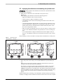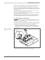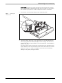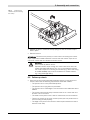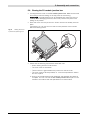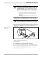
1
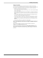
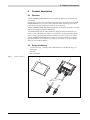
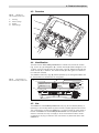
Installation manual for PV-Module-Manufacturer SAMKO 100 01 KIE_Montageanleitung_Samko_100_01.indd 1 23.07.13 08:50 About us KOSTAL Industrie Elektrik GmbH An der Bellmerei 10 58513 Lüdenscheid Germany Telephone: +49 2351 16 - 0 Fax: +49 2351 16 - 2400 [email protected] Postal address: KOSTAL Industrie Elektrik GmbH Lange Eck 11 58099 Hagen Germany Telephone: +49 2331 8040 - 4800 Fax: +49 2331 8040 - 4601 Exclusion of liability All names of usage, trade names, product names or other designations given in this manual may be legally protected even without special labelling (e.g.as a trademark). The KOSTAL company assumes no liability for their free usage. The illustrations and texts have been compiled with great care. However, the possibility of errors cannot be ruled out. There is no guarantee of the correctness of the illustrations and texts in this compilation. General note on non-discrimination The KOSTAL company publishers are aware of the meaning of language with regard to the equality of women and men and always make an effort to reflect this in the documentation. Nevertheless, for the sake of readability we are unable to use non-gender-specific terms throughout and have used the masculine form as a rule. © 2013 KOSTAL Industrie Elektrik GmbH All rights reserved by KOSTAL, including those of reproduction by photocopy and storage in electronic media. Commercial use or distribution of the texts, models, diagrams and photographs appearing in this product is not permitted. This manual may not be reproduced, stored, transmitted or translated in any form or by means of any medium – in whole or in part – without prior written permission. Table of contents Table of contents 10215641-02en 1 Important notes ··················································································4 1.1 Typographical conventions···························································4 1.2 Scope of validity···········································································4 1.3 Safety instructions········································································4 2 Proper use ··························································································5 3 Safety instructions··············································································6 4 Product description············································································8 4.1 Function·······················································································8 4.2 Scope of delivery ·········································································8 4.3 Overview······················································································9 4.4 Identification·················································································9 4.5 Use ··························································································9 4.6 Technical data ············································································10 5 Assembly and connection································································11 5.1 Preparing the contact strips ·······················································11 5.2 Preparing the adhesion surfaces ················································11 5.3 Applying the adhesive and mounting the junction box················12 5.4 Connecting the contact strips ····················································13 5.5 Follow-up check ········································································15 5.6 Closing the PV module junction box···········································16 5.7 Opening the PV module junction box ·········································17 5.8 Instructions for semi-automatic assembly ··································17 3 1: Important notes 1 Important notes This manual contains important information regarding the features and handling of the SAMKO 01 photovoltaic module junction box by KOSTAL. Read this manual carefully in its entirety. KOSTAL assumes no liability for any damage resulting from the non-observance of this manual. 1.1 Typographical conventions The following typographical conventions are used in this manual: — Lists are marked with a dash. Instruction steps are marked with a dot. ➙ This arrow indicates the result of an action. 1.2 Scope of validity This manual is an integral part of the product. It applies exclusively to the photovoltaic module junction box SAMKO 01, whereby, to simplify matters, the designation SAMKO 01 covers the variant SAMKO 100 01. Please send any questions concerning the validity of this manual to: KOSTAL Industrie Elektrik GmbH Lange Eck 11 58099 Hagen, Germany Telephone: +49 2331 8040 – 4800 Fax: +49 2331 8040 - 4601 1.3 Safety instructions Information concerning your safety or that of the unit is specially highlighted. DANGER Non-observance of safety warnings marked with the signal word DANGER can cause fatal injuries. WARNING Non-observance of safety warnings marked with the signal word WARNING, can cause serious and/or permanent injuries. CAUTION Non-observance of safety warnings marked with the signal word CAUTION, can cause minor and/or reversible injuries. ATTENTION Non-observance of safety warnings marked with the signal word ATTENTION, can cause damage to property. 10215641-02en 4 2: Proper use 2 Proper use The PV module junction box enables a PV module to be electrically connected to other suitable components. The electrical specifications of the PV module and the PV module junction box must match. The PV module junction box is attached to the back of the PV module using adhesive. In order to do this, there must be sufficient installation space on the PV module. Where necessary, the method of attachment, joining parts to be used (adhesives and rear side) and how to combine them are explained in the applicable certificates. Contact must only be made with the components described here and in the way described here. Inappropriate use can be hazardous and lead to injury or even death of the operator or third parties. Material damage to the unit and other equipment can also occur. The PV module junction box may therefore only be used for its intended purpose. Exclusion of liability Any use that differs from or goes beyond the stated intended purpose is considered inappropriate. The manufacturer accepts no liability for any damage resulting from such use. It is forbidden to make alterations to the PV module junction box. The PV module junction box may only be used if safe to operate and in technically perfect condition. Any instance of misuse will void the warranty, guarantee and general liability of the manufacturer. In particular, the following actions constitute improper use: — The electrical connection with non-structurally identical PV module junction boxes of other types or brands without the express approval of KOSTAL. — Contacting using cables or wires other than those specified within the interior of the junction box instead of the prescribed contact strips. — Unfastening the cable fittings on the junction box. — Shortening or replacing the cable attached at the factory. — Replacing the plug, regardless of type or manufacturer, without the express approval of KOSTAL. — Applying force to the attached PV module junction box during transport, assembly or operation. This also applies to both open or closed junction box bodies and the attached cables and plug connectors. — Removing or covering safety notices. 10215641-02en 5 3: Safety instructions 3 Safety instructions DANGER Improper handling during installation and while operating the PV module junction box can lead to potentially fatal electric shock. Always observe all the safety instructions in this manual. Risk of damage due to excessive application of force: forces and torques that affect or may affect the connection equipment must be kept to a minimum at all times, regardless of the standards-assessed characteristics, in order to prevent damages and premature failure. Markings The labels and markings applied to the housing by the manufacturer may not be changed or removed. The unit bears the following markings: Warning: high voltage Do not disconnect while live Electrical protection class II acc. to DIN EN 61140 Rated voltage acc. with EN 50548 Protection class acc. to DIN EN 60529 Rated voltage acc. to UL 1703 / UL 3730 Instructions on opening the cover Opening the unit DANGER During operation, there are potentially fatal levels of voltage in the PV module junction box. Touching live parts, and even opening the junction box while it is still connected to the power supply, may induce a fatal electric shock. Perform the following steps before opening the PV module junction box: Disconnect the device from the power supply at all sides. Secure the power supply from being unintentionally switched back on. Check the device and cables to make certain that they are voltage-free. Disconnecting cables The plug connector and contact strips may only be disconnected by a qualified electrician. The plug connector and contact strips must not be removed while still live. 10215641-02en 6 3: Safety instructions Usage in the field In order to prevent damages and premature failure, observe the following points when laying cables between the individual PV modules and between the PV modules, the inverters and other parts of the PV module combination: — Wear the prescribed protective clothing. — Do not leave cables or plug connectors lying in dirt or water (make drainage holes in cable ducts). — Do not leave cables hanging by their own weight or in positions where they are susceptible to long-term movement by the wind (increased mechanical aging). — Do not leave cables or plug connectors exposed across transport and travel routes or areas where things may be put down. — Do not allow cables or cable ends, in particular the cable inputs to the PV module junction box or the PV plug connector to be subjected to tension. Take into account possible causes of expansion due to fluctuations in temperature. — Do not allow cables to be guided over sharp edges. Work carefully, taking particular care not to damage the PV plug connector, its seals, contact elements or other parts when using it to establish the electrical connection. Allow sufficient ventilation at the rear of all PV modules into which the SAMKO 01 PV module junction box is built. Care must also be taken to ensure that the PV module junction box and its electrical and mechanical connections are not subjected to permanent pressure, tension or torque from any direction (e.g. due to supports or other components). 10215641-02en 7 4: Product description 4 Product description 4.1 Function The PV module junction box is used to provide an electrical connection to a PV module. Usually, up to three of a PV modules cell strings are connected in the PV module junction box via up to four contact strips (one per cell string, plus one extra). Pressure/spring contacts are used for the contacting. The PV module junction box uses special semi-conductors to protect the solar cells from damage in cases of shadowing. The sealed design with an IP65 protection rating protects the electrical connections from penetration by water or contaminant. A pressure balancing element is used to guarantee the defined ventilation for the junction box interior. The PV module junction box is used either to connect multiple PV modules with each other or to connect a PV module to an inverter or to other components of a PV module network. 4.2 Scope of delivery — Junction box (Fig. 1 Item 4), with cables (ready for use) (2) and plug connectors (3) — Cover (1) — Documentation Fig. 1 Scope of delivery 1 4 2 3 10215641-02en 8 4: Product description 4.3 Overview Fig. 2 SAMKO 01 PV module junction box 1 2 3 4 Housing Clamp springs Diodes Cable fittings 1 2 3 4 4.4 Identification The side of each PV module junction box is market with the article number (Fig. 3, item 1), type designation (2) , revision status (3), Rated Voltage acc. UL 1730/UL 3730 (for articles with UL regocnition only) (4), Rated Current (5) and serial number (7). In addition, the serial number (7) is also given as a data matrix code (2D code, 8). The “Made in Germany”-sign (6) will be replaced by UL Recognition Mark and UL File Number for articles with UL recognition Fig. 3 Identification of the PV module junction box 1 7 6 8 /30SLKnnnnnnnn SAMKO 100 01 ttuuvv wwxxyyzz /SNTTTTTYMDXXXXX 10A 600V HW0000 2 5 4 3 10A 600V 4.5 Use The SAMKO 01 PV module junction box may only be connected (directly or indirectly) to structurally identical junction boxes. Express approval from KOSTAL is required to connect the SAMKO 01 to junction boxes of other types or brands. All SAMKO 01 PV module junction boxes are compatible with one another. However, this may not apply to some customised models, certain combinations of plug connectors and connections of panels that are fit with SAMKO 01. 10215641-02en 9 4: Product description In order to connect the SAMKO 01 PV module junction box to other devices (junction boxes, inverters etc.), you must use the same type and brand of plug connector as supplied. Ensure that all third-party plug connectors are expressly tested and certified before use. 4.6 Technical data The SAMKO 01 PV module junction box is available with certification from the TÜV Rheinland and UL. The rated voltage for UL-certified PV junction boxes is 600 V according to UL 1703/UL 3730. This does not affect the European standard rated voltage of 1000 V. UL-certified junction boxes bear the “recognition mark” and the corresponding file number (E328235). Tab. 1 Technical data SAMKO 01 Manufacturer KOSTAL Industrie Elektrik GmbH Designation SAMKO 100 01 Rated current 10 A SAMKO 100 01 (Schottky Diode) (acc. to EN 50548:2011+A1:2013 and UL 1703 / UL 3730) Rated surge voltage 8 kV (in acc. with EN 50548:2011+A1:2013) Rated voltage 1000 V (in acc. with EN 50548:2011+A1:2013) 600 V (in acc. with UL 1703/UL 3730) Max. permitted operating voltage 100 V SAMKO 100 01 (in acc. with EN 50548:2011+A1:2013) Connectable cable cross-sections 4 mm²/AWG 12 (werkseitig montiert) Connectable contact strips Width 3.5...10 mm Thickness 0.3...0.75 mm Tin-plated surface, special testing required for other surfaces. Number of diodes max. 3 Protection rating IP 65 DIN EN 60529 Pollution degree housing interior: 2 (acc. to EN 60664-1) housing exterior: 3 (acc. to EN 60664-1) Overvoltage category III (EN 60664-1) Flammability class 5 VA (UL 94) Max. dimensions (L x W x H) 132 mm × 125 mm × 27 mm Certification: — TÜV Rheinland certification in acc. with EN 50548:2011+A1:2013) (certification number R60091059) — Certification to UL 1703/UL/ 3730 (UL File Number E328235) Other properties: — RoHS-compliant — Halogen-free acc. to DIN VDE 0472 Part 815 — Vapour pressure balancing via breathable membrane with IP 65 protection 10215641-02en 10 5: Assembly and connection 5 Assembly and connection ATTENTION Risk of damage due to electrostatic discharge (ESD). The PV module junction box contains electric components that can be damaged or destroyed by electrostatic discharge. Implement measures to prevent ESD damage (cf. DIN EN 61340-5-1/-2). In order to ensure that the adhesion surfaces of the PV module junction box and the PV module are not contaminated by oils (especially silicone oils), greases, dust, dirt, moisture etc., only touch and handle the junction box with clean gloves or using clean tools. Work carefully and keep all tools and components clean: no dirt, contaminant or moisture must be allowed to penetrate the junction box. Some assembly aids such as oils and greases may be chemically incompatible with the plastic of the junction box. Consult KOSTAL before using any assembly aids. 5.1 Preparing the contact strips Before mounting the PV module junction box, place the contact strips in a suitable position for the assembly process in order to ensure that the joint is not subjected to any application of force before it has reached its full adhesive force. 5.2 Preparing the adhesion surfaces The adhesion surfaces of the PV module junction box and the PV module must fulfil the requirements of the adhesive manufacturer. Usually, this means at least that the surface must be clean, dry and free of dust, oil, grease and silicone residue. Perfectly prepared adhesion surfaces are key to ensuring a strong bond. Treat the adhesion surfaces of the junction box and the PV module in accordance with the adhesive manufacturer's specifications. The adhesive manufacturer may specify that the surfaces of the joining parts must be treated specially to prepare them for adhesion. If you are unsure about any part of this process, please consult the adhesive manufacturer. 10215641-02en 11 5: Assembly and connection 5.3 Applying the adhesive and mounting the junction box ATTENTION! Always observe the adhesive manufacturer's specifications when working with the adhesive. Apply a line of adhesive to the underside of the junction box (see Fig. 4). When applying the adhesive, observe the following points: — Apply the adhesive with an even thickness. — There must be no gaps or bubbles in the line. — The adhesive must surround all openings that lead to the inside of the junction box. — The residual adhesive strength after mounting must be sufficient to elastically compensate for differences in the expansion behaviour of the materials involved and to withstand environmental influences (wind, snow etc.) over a long period of time. — After mounting, the adhesive must not cross into the four contact points for the cover. Hardened adhesive may prevent the cover from being closed. — It is not permissible to apply the adhesive around the edge of the junction box. This applies in particular to the areas around the cover contact points. Work carefully; you will not be able to visually check the adhesion at a later point. Fig. 4 Application of adhesive (Correct – Incorrect) ✓ right ✗ wrong ✗ wrong Press the junction box evenly onto the PV module in the prescribed position. Make sure to press down precisely vertically, otherwise the junction box may slip to the side and smear the adhesive. The spacer on the rear ensures that the adhesive is at least 0.5 mm thick. There may be a larger clearance between the junction box and the PV module if required due to the adhesive or the desired mechanical properties of the joint. Make sure that the clearance is kept constant during the drying phase. Please note: thicker layers of adhesive may prolong the drying phase. While the adhesive is hardening, the subsequent operational steps (contacting, transport, storage) must be carried out with the utmost care so as not to impair 10215641-02en 12 5: Assembly and connection the adhesive result. For example, the PV module should only be transported and stored in a horizontal position, otherwise the junction box may slip. Make a note of the weight and rigidity of the cable harness. In unfavourable conditions, e.g. during transportation of the PV module and in particular before the adhesive has fully hardened, the junction box may be lifted off the module by the cable harness. Several different mounting materials have been certified for this PV module junction box by TÜV Rheinland LGA Products GmbH. Contact the junction box manufacturer for a list of possible mounting adhesives that habe been certified for this junction box. Contact the junction box manufacturer for a list of possible PV module backsheet materials (material groups PVF, PVDF, PA, ETFE, Glas) that have already been certified with this junction box for the use as mounting adhesives. 5.4 Connecting the contact strips ATTENTION! The clamp springs on the PV module junction box are only suitable for use with contact strips (cf. Section 4.6). Cables and other wires are not suitable for use with the clamp springs. If you wish to connect contact strips while the adhesive is still drying, take care to ensure that you do not impair the quality of the joint. For example, it may be advisable to use an adhesive pad to fix the joint in place temporarily. A suitable tool is required to open the clamp springs. Please contact KOSTAL regarding this issue. A flat-headed screwdriver with a shaft length of at least 30 mm and a maximum blade width of 4 mm is also suitable for this purpose. Fig. 5 Inserting the tool and opening the clamp spring Insert the tool into the square opening of the clamp spring. 10215641-02en 13 5: Assembly and connection ATTENTION! Pulling on the clamp springs may exert forces and moments that could damage the adhesive bond with the PV module. Fix the junction box in place, e.g. by hand, in order to keep such forces to a minimum. Pull the lever until the clamp spring is open sufficiently wide. Fig. 6 Inserting the contact strip 1 2 3 Insert the contact strips (Fig. 6, Item 1) vertically into the gap between the clamp spring (2) and the diode plate (3) as far as it will go. The area of the contact strip that is to be clamped must not be deformed, contaminated or kinked in any way. The entire surface of the contact strip must be free of oils, greases and any other substances that can prevent electrical contact and impair the contact resistance. There is no need to strengthen the connection by soldering, welding or using other joining processes. 10215641-02en 14 5: Assembly and connection Fig. 7 Inserting the contact strip and closing the clamp Release the lever to relieve the clamp springs so that the contact strip is fixed in place. Remove the tool. ATTENTION: Ensure that the polarity is correct when connecting the contact strips. Implement suitable measures to ensure that the contact strips do not come into contact with one another and short-circuit. DANGER Risk of death by electric shock. Exposed contact strips coming into contact with each other can create potentially fatal electric arcs. If it is not possible to prevent the contact strips from crossing one another (e.g. due to the wiring of the PV module), they must be insulated in a suitable manner, e.g. using shrinkage tubing. 5.5 Follow-up check Once the junction boxes have been attached and the contact strips connected, check that the following requirements have been fulfilled: — The junction box is in the prescribed position. — The junction box is lying flat on the laminate. — The junction box is undamaged. The connections and cables are free of defects. — The contact strips are securely connected and not in contact with one another or short-circuited. — The inside of the junction box is free of contaminant, dirt and moisture. — There is no silicone at the cover contact points (this can prevent the cover from being closed properly). — The edge of the junction box is free of silicone (this will later be used to seat the cover seal). 10215641-02en 15 5: Assembly and connection 5.6 Closing the PV module junction box Loosely place the cover on the PV module junction box. Make sure that the four locking hooks are resting on the clip points of the housing. ATTENTION: If the adhesive has not yet hardened fully, press the cover on carefully. Avoid damaging the bond, as this may result in the junction box sliding out of position. Press the cover onto the junction box. All four hooks must audibly click into place. If necessary, you can use a tool to exert counter-pressure at the notches below the locking hooks. Fig. 8 Setting the cover in place and pressing it on Check that the following requirements have been met: — All four locking hooks must be closed. — The cover must not be askew. — There must be no gap between the junction box and the cover. — The cover must be securely seated, i.e. it must be impossible to slide or lift it out of place. ➙ As soon as the adhesive has fully hardened, the assembly procedure is complete. You can now use the PV module junction box as part of a PV module in accordance with the specifications for said module. 10215641-02en 16 5: Assembly and connection 5.7 Opening the PV module junction box DANGER During operation, there are potentially fatal levels of voltage in the PV module junction box. Touching live parts, and even opening the junction box while it is still connected to the power supply, may induce a fatal electric shock. Perform the following steps before opening the PV module junction box: Disconnect the device from the power supply at all sides. Secure the power supply from being unintentionally switched back on. Check the device and cables to make certain that they are voltage-free. Insert a suitable tool (e.g. flat-headed screwdriver at least 30 mm shaft length and maximum 3 mm blade width) into one of the four side openings on the cover. DANGER Risk of death by electric shock. Risk of damage to the PV module. There are electric wires beneath the panel laminate. Insert the tool gently so as to avoid touching live parts and to prevent the PV module from being damaged if the tool slips. Move the tool in a levering motion towards the PV module to release the locking hook. Fig. 9 Releasing the locking hook Repeat this process for each locking hook. Remove the cover. 5.8 Instructions for semi-automatic assembly The junction box can be attached and connected automatically. With the exception of the section on connecting the contact strips, the procedure outlined in these instructions is transferrable for such a purpose. A (semi-)automatic handling and working concept is subject to special requirements for ESD conformity. 10215641-02en 17 Phone: +49 2331 8040-4800 Fax: +49 2331 8040-4811 www.kostal.com/industrie KIE_Montageanleitung_Samko_100_01.indd 2 DOC01117245-0008 – 01.2014 – MA – EN KOSTAL Industrie Elektrik GmbH (KOSTAL Industrial Electronics) Lange Eck 11 58099 Hagen Germany 23.07.13 08:50