1
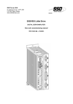
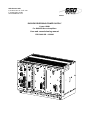
SSD Parvex SAS
8, avenue du Lac - B.P. 249
F-21007 Dijon Cedex
www.SSDdrives.com
DIGIVEX REVERSING POWER SUPPLY
Power 15KW
For DIGIVEX Servo-Amplifiers
User and commissioning manual
PVD 3492 GB – 01/2003
PRODUCT RANGE
1-
« BRUSHLESS » SERVODRIVES
TORQUE OR POWER
RANGES
•
•
•
2-
BRUSHLESS SERVOMOTORS, LOW INERTIA, WITH RESOLVER
Very high torque/inertia ratio (high dynamic performance machinery):
⇒ NX -HX - HXA
⇒ NX - LX
High rotor inertia for better inertia load matching:
⇒ HS - LS
Varied geometrical choice :
⇒ short motors range HS - LS
⇒ or small diameter motors : HD, LD
Voltages to suit different mains supplies :
⇒ 230V
three-phase for «série L - NX»
⇒ 400V, 460V three-phase for «série H - NX»
"DIGIVEX DRIVE" DIGITAL SERVOAMPLIFIERS
⇒ SINGLE-AXIS
DSD
⇒ COMPACT SINGLE-AXIS
DLD
⇒ POWER SINGLE-AXIS
DPD
⇒ MULTIPLE-AXIS
DMD
"PARVEX MOTION EXPLORER" ADJUSTING SOFTWARE
0,9 to 320 N.m
0,3 to 54 N.m
3,3 to 31 N.m
3,3 to 31 N.m
9 to 100 N.m
SPINDLE DRIVES
•
•
3-
SPINDLE SYNCHRONOUS MOTORS
⇒ "HV" COMPACT SERIES
⇒ "HW" ELECTROSPINDLE,frameless, water-cooled motor
From 5 to 110 kW
up to 60,000 rpm
"DIGIVEX" DIGITAL SERVOAMPLIFIERS
DC SERVODRIVES
•
•
•
4-
"AXEM", "RS", "RX" SERIES SERVOMOTORS
"RTS" SERVOAMPLIFIERS
"RTE" SERVOAMPLIFIERS for DC motors + resolver giving position
measurement
0.08 to 13 N.m
SPECIAL ADAPTATION SERVODRIVES
•
•
5-
"XD" SERVOMOTORS for explosive atmosphere
"AXL" COMPACT SERIES SERVOREDUCERS
POSITIONING SYSTEMS
•
•
•
•
COMMANDE NUMERIQUE « CYBER 2000 » 1 à 2 axes
"CYBER 2000" NC 1 to 2 axes
VARIABLE SPEED DRIVE - POSITIONER
⇒ SINGLE-AXIS
DSM
⇒ POWER SINGLE-AXIS
DPM
⇒ MULTIPLE-AXIS
DMM
ADJUSTMENT AND PROGRAMMING SOFTWARE PARVEX MOTION EXPLORER
0.7 to 20 N.m
5 to 700 N.m
15 kW Reversing Power Supply for Digivex Servo-Amplifiers
CONTENTS
SAFETY INSTRUCTIONS………………………………………………………………………..………2
1.
1.1
1.2
1.3
1.4
GENERAL
4
Digital servodrive
DIGIVEX REVERSING POWER SUPPLY module general characteristics
Presentations / Block diagram
Return of braking energy to mains supply
2. DIGIVEX REVERSING POWER SUPPLY
CONNECTION
2.1
2.2
2.3
2.4
2.5
2.6
Front-panel terminal blocks
Power component size requirements
Mains supply connection
"Low-level" auxiliary supply connection
Control signal connection (X2 and X3 terminal blocks)
X1 terminal block "Brake Supply" connection
4
5
5
7
11
11
12
13
14
15
18
3.
LEDS AND OPERATING DIAGNOSTICS
18
4.
INITIALIZATION AND STOP SEQUENCES
19
5.
LABELLING - CODING
20
Characteristics and dimensions are liable to modification without notice.
YOUR LOCAL CORRESPONDENT
SSD Parvex SAS
8 Avenue du Lac / B.P 249 / F-21007 Dijon Cedex
Tél. : +33 (0)3 80 42 41 40 / Fax : +33 (0)3 80 42 41 23
www.SSDdrives.com
1
PVD 3492 GB 03/2003
15 kW Reversing Power Supply for Digivex Servo-Amplifiers
SAFETY
Servodrives present two main types of hazard :
- Electrical hazard
Servoamplifiers may contain non-insulated live AC or DC
components. Users are advised to guard against access to live
parts before installing the equipment.
Even after the electrical panel is de-energized, voltages may be
present for more than a minute, until the power capacitors have
had time to discharge.
Specific features of the installation need to be studied to prevent
any accidental contact with live components :
- Connector lug protection ;
- Correctly fitted protection and earthing features ;
- Workplace insulation
(enclosure insulation humidity, etc.).
General recommendations :
• Check the bonding circuit;
• Lock the electrical cabinets;
• Use standardised equipment.
- Mechanical hazard
Servomotors can accelerate in milliseconds. Moving parts must be
screened off to prevent operators coming into contact with them.
The working procedure must allow the operator to keep well clear
of the danger area.
All assembly and commissioning work must be done by qualified
personnel who is familiar with the safety regulations (e.g. VDE
0105 or accreditation C18510).
2
PVD 3492 GB 03/2003
15 kW Reversing Power Supply for Digivex Servo-Amplifiers
Upon delivery
All servoamplifiers are thoroughly inspected during manufacture and tested at length
before shipment.
•
•
Unpack the servoamplifier carefully and check it is in good condition.
Also check that data on the manufacturer's plate comply with data on the order
acknowledgement.
If equipment has been damaged during transport, the addressee must file a complaint with the
carrier by recorded delivery mail within 24 hours.
Caution :
The packaging may contain essential documents or accessories, in particular :
• User Manual,
• Connectors.
Storage
Until installed, the servoamplifier must be stored in a dry place safe from sudden
temperature changes so condensation cannot form.
Special instructions for setting up the equipment
CAUTION
For this equipment to work correctly and safely it must be
transported, stored, installed and assembled in accordance with
this manual and must receive thorough care and attention..
Failure to comply with these safety instructions may lead to
serious injury or damage.
The cards contain components that are sensitive to electrostatic
discharges. Before touching a card you must get rid of the static
electricity on your body. The simplest way to do this is to touch a
conductive object that is connected to earth (e.g. bare metal
parts of equipment cabinets or earth pins of plugs).
3
PVD 3492 GB 03/2003
15 kW Reversing Power Supply for Digivex Servo-Amplifiers
1. GENERAL
This document supplements the technical instruction PVD 3464 concerning the Digivex
Servoamplifier. It describes a power supply variant - DIGIVEX REVERSING POWER SUPPLY which is designed to return braking energy to the mains supply. The DIGIVEX POWER SUPPLY
version described in instruction PVD 3464 is designed to dissipate braking energy via a resistor.
The general wiring requirements as given in instruction PVD 3464 apply to the DIGIVEX
REVERSING POWER SUPPLY. The same is true of compliance with standards.
1.1 Digital servodrive
All these servodrives comprise:
•
Brushless servomotors, with permanent magnets, whose emf is of a sine-wave form,
with position measurement by resolver. HX, HS, HD range servomotors. HV and HW
range spindle motors can also be used (these two motor ranges are covered by
separate documentation).
•
A multiple-axis electronic control system made up of:
♦ a rack, see instruction PVD 3464.
♦ a power supply module that receives the 400V(460) /50-60Hz mains supply
directly and provides 550V bus voltage. This module also commands energy
dissipation.
•
Control modules connected to the servomotor (power and resolver), see instruction
PVD 3464.
4
PVD 3492 GB 03/2003
15 kW Reversing Power Supply for Digivex Servo-Amplifiers
1.2 DIGIVEX REVERSING POWER SUPPLY module
general characteristics
TYPE
MAINS SUPPLY
400 V threephase
REVERSING POWER
48 - 62 Hz
SUPPLY
Max 460V +10%
MEAN BUS
RATED BUS
CURRENT
VOLTAGE
RECOVERY
550 V
RETURN TO
MAINS SUPPLY
DIGIVEX
30 A
The module's dimensions are identical to that described in the instruction PVD 3464. The rack
composition (power supply + servoamplifiers) follows the same rules.
1.3 Presentations / Block diagram
The power supply is placed in the left-hand part of the rack:
• It receives the 400V(460) three-phase mains supply (terminal block B2) and provides
the dc voltage power output (550 V internal bus) to the DIGIVEX servoamplifiers.
•
It receives the 400V(460) single-phase auxiliary mains supply (terminal block B1) and
provides a dc voltage of 550V. Each DIGIVEX DRIVE generates its own voltages from
this "low-level bus" ± 15V, 5V, 24V.
•
It may receive a 24V source (terminal block X1) for the servomotor brakes and
distributes it to the axes via the internal bus.
•
It provides the 24V and ± 15V "customer" auxiliary supplies (terminal block X3).
•
It ensures the logic interface with the main contactor control (terminal block X2).
•
It ensures the interface with the emergency stop control and external reset (terminal
block X3).
A series of LEDs can be used to check the power supply and drive status
5
PVD 3492 GB 03/2003
15 kW Reversing Power Supply for Digivex Servo-Amplifiers
U1
+
V1
W1
POWER
BUS
550V
POWER
SYNCHRO
I POWER
BUS
MONITORING
u1
v1
24V
+15V
0V
-15V
-
MAINS MONITORING
AUXILIARIES
AUX. AXIS
SUPPLY
AUXILIARIES
CHOPPED
SUPPLY
RADIATOR
TEMPERATURE
SAFETY
MANAGEMENT
N = 0 AXIS
.
AXIS INIT
RESET
EMERGENCY
24V
FANS
STOP
READY
OK
BRAKES
24V SUPPLY
SYNOREVF.DS4
6
PVD 3492 GB 03/2003
24V
FOR
AXIS FANS
15 kW Reversing Power Supply for Digivex Servo-Amplifiers
1.4 Return of braking energy to mains supply
The bi-directional bridge of the REVERSING POWER SUPPLY is used to return the energy
generated during braking to the mains supply. This feature enables operation under permanent
braking regime at 15 kW and 20 kW for 2 seconds under the pulse regime.
The mean power required of the supply, both in motor regime and braking regime, must not
exceed 15 kW.
It is mandatory to fit an inductor (product number SF02040) between the DIGIVEX REVERSING
POWER SUPPLY and the mains (see connection drawing FELX 305388). This inductor does not
dispense with the use of a mains filter. The mains supply must have available power of at least
20 kVA. The mains voltage must not vary by more than 5% when the power absorbed or restored
by the DIGIVEX REVERSING POWER SUPPLY varies from 0 to 20 kW.
7
PVD 3492 GB 03/2003
15 kW Reversing Power Supply for Digivex Servo-Amplifiers
8
PVD 3492 GB 03/2003
15 kW Reversing Power Supply for Digivex Servo-Amplifiers
9
PVD 3492 GB 03/2003
15 kW Reversing Power Supply for Digivex Servo-Amplifiers
10
PVD 3492 GB 03/2003
15 kW Reversing Power Supply for Digivex Servo-Amplifiers
2. DIGIVEX REVERSING POWER SUPPLY
CONNECTION
2.1 Front-panel terminal blocks
All the connections are brought to the front
panel:
B1 : "Auxiliary" power supply (low-level)
B2 : Mains input
X1 : 24V power supply for brake
X2 : Main contactor automatic control interface
X3 : 24V, ±15V outputs, reset and zero speed
11
PVD 3492 GB 03/2003
15 kW Reversing Power Supply for Digivex Servo-Amplifiers
General characteristics of terminal blocks
Summary table, showing for terminal blocks B1, B2, X1, X2 and X3:
•
•
•
the type of terminal block.
the maximum cross-section (S) accommodated by the terminal block.
the recommended clamping torque (C) for the terminal block.
TERMINAL 15 kW REVERSING POWER SUPPLY
BLOCK
B1
screw-type, S = 4 mm² flexible wire,
S = 6 mm² rigid wire C = 0.8 Nm
B2
screw-type, S = 6 mm² flexible wire,
S = 10 mm² rigid wire, C = 1.8 Nm
X1 - X3
spring-type, S = 2.5mm²
2.2 Power component size requirements
Applicable to the components ahead of the DIGIVEX POWER SUPPLY (fuses, cables,
contactors, etc.), these dimensions are dependent on:
•
•
Permanent currents (sine-wave peak) at low speed for each motor, as given in the
characteristics (Î0).
The axis simultanetly coefficient.
If this coefficient is assumed to be 1, and cosϕ = 1, we can write:
P electric at mains ≅ 1.1 Urms. ∑ Î0
I rms mains =
P
Urms. 3
12
PVD 3492 GB 03/2003
15 kW Reversing Power Supply for Digivex Servo-Amplifiers
MAINS INPUT
POWER 400 V
kW
FUSE RATING
Type gG
MAINS
FILTER
Â
LINE CURRENT for mains
Urms = 400 V
A eff.
∑ Î0
15
40
25
32
FR 03036
Cable cross-section and contactor ratings must be chosen in consequence.
See instruction PVD 3464.
The equipment complies with European Standard EN55011 with a filter on the power input. The
approved filter reference number is FR03036.
2.3 Mains supply connection
Three-phase 400V rms power supply (460V + 10% max.) via terminal block B2 "MAINS SUPPLY":
terminals U1 - V1 - W1
The mains supply voltage at 50/60 Hz must be greater than 200 V rms and less than 510V rms
for use with 480V + 10%, a transformer or autotransformer is required (power greater than 20
kVA).
Current : 25A rms.
Derating with temperature :
• Derating of 2% per degree centigrade above 40°C.
• Maximum ambient temperature 60°C.
A thermal detector causes the "OK" relay to open when the dissipater reaches 85°C.
Derating with altitude: derating of 1% per 100 m above 1000 m.
Terminal block B2 "MAINS SUPPLY": Marked U1 - V1 - W1.
Mains monitoring :
• maximum mains voltage (520V rms).
Power bus monitoring :
• Maximum bus voltage (750 V).
• Minimum bus voltage (200 V).
Dissipated power: 70 W.
13
PVD 3492 GB 03/2003
15 kW Reversing Power Supply for Digivex Servo-Amplifiers
2.4 "Low-level" auxiliary supply connection
Terminal Block B1.
Each DIGIVEX DRIVE takes its "low-level" power supply from a "low-level bus" and produces the
± 15V / 5V levels it requires via a chopped supply and transformer.
This "low-level power supply" bus, with voltage between 290V and 750V, is obtained through
terminal block B1 from a single-phase source, which may be:
•
either 200 - 520V single-phase taken between two phases ahead of the main
contactor.
•
or a separate 200 - 520V supply. In this case, it is mandatory to provide an isolating
transformer (160VA, e.g. primary 200 - 520V single-phase ±10%, secondary 230V
±10%).
The advantage of these solutions is to be able to cut out separately the power part, and to keep
the LED fault display and the encoder emulation counting capability.
Internal fuse:
The fuse is marked F1 and protects the chopped supply: Type 500V / 1.6A.
Auxiliary supply monitoring, power supply present.
•
The auxiliary power supply also provides 24V dc for the rack fans, the rack is therefore
cooled whenever the low-level supply is present
Low-level consumption: 30 W
14
PVD 3492 GB 03/2003
15 kW Reversing Power Supply for Digivex Servo-Amplifiers
2.5 Control signal connection (X2 and X3 terminal blocks)
Unpluggable terminal blocks
TERMINAL BLOCK X2
1-2
Output
"READY" contact
3-4
Output
"OK" contact
Potential free contacts
U max = 250V
Cut-out power = 250VA 1A
(Ohmic charge)
- X2/1.2 : "READY" contact
This contact is closed if:
• the "AUX" bus (low-level) is correct, > 290V dc when started up
• at least one axis is present in the rack
• the drives have not indicated fault conditions when their "low-level" power supplies
came on
This contact enables the main contactor to close
• the red "POWER OFF" LED is on
ATTENTION: The KM power contactor can only be closed if the auxiliary supply is present
and if the "READY" contact is closed.
- X2/3.4 : "OK" contact
This contact is closed if:
• the "AUX" power supply is correct
• the power supply is present (> 200V dc)
• the drives, low-levels and power, do not indicate any fault conditions
This contact enables the main contactor to self-hold
• the green "POWER ON" LED is on
ATTENTION : Opening the OK contactor must cause the main contactor to open with a
maximum 100 ms delay.
15
PVD 3492 GB 03/2003
15 kW Reversing Power Supply for Digivex Servo-Amplifiers
The "OK" relays open in the following cases:
•
•
•
•
•
•
•
•
Max. mains supply (more than 520V rms with 0.1s time delay).
No phase.
OVERPOWER fault.
Maximum bus voltage with 0.3 s time delay.
Minimum bus voltage.
Fault on one axis, in absence of return of energy to mains.
Auxiliary power supply fault.
Overcurrent (0.1 s) time delay or no inductor.
TERMINAL BLOCK X3
1
Output
24V regulated
2
Output
0V of 24V
3
Output
15V regulated
4
Output
0V of +/- 15V
5
Output
- 15V regulated
6
Input
+ Reset
7
Input
- Reset
8
Input
+ Emergency Stop
9
Input
- Emergency Stop
- X3/1
24V regulated
- X3/2
0V of 24V
•
•
24V -50 mA power supply. Do not use to supply motor brakes.
Protection against overloads and short-circuits by resettable fuse.
This power supply is for logic inputs but is also used internally to supply the fans. There is no
common point with the metal framp.
16
PVD 3492 GB 03/2003
15 kW Reversing Power Supply for Digivex Servo-Amplifiers
- X3/3
+15V regulated
- X3/4
0V of 15V
- X3/5
•
•
-15V regulated
±15V - max. 10mA
Protection by electronic circuit breaking
This power supply is in common with the DIGIVEX REVERSING POWER SUPPLY internal
power supply
- X3/6 - X3/9 Logic inputs
Common characteristics of these different inputs:
•
•
24V dc opto-coupled inputs (isolation voltage 1 kV)
type 2 inputs after IEC 1131-2
These inputs may be connected directly to PNP type outputs (external load resistance not
required).
MIN
TYPICAL
MAX
input voltage - level 0
-
0V
5V
input voltage - level 1
11V
24V
30V
Input current - level 0
-
0mA
2mA
Input current - level 1
7mA
13mA
15mA
Response time T "on" (0 to 1)
-
1ms
-
Response time T "on" (1 to 0)
-
1ms
-
- X3/6 et X3/7
Reset
A 24V rising edge applied to X3/6 relative to X3/7 causes a reset (clear) after the power supply
or drive fault.
Notice that the system can also be reset with the "reset" button on the front panel, or by deenergizing the system completely (power and auxiliaries).
This control has no effect in normal operation.
- X3/8 et X3/9
Emergency Stop, in speed loop mode only
A 24V voltage must be applied across terminals X3/8 (+) and X3/9 (-) to enable drive operation.
The 24V may be taken from X3 terminals 1 and 2.
The disappearance of the 24V on X3/8 - X3/9 acts on all drives, to provide dynamic braking. This
is a help for category 1 or 2 stops under standard EN 60204 Chapter 8.2.2.
17
PVD 3492 GB 03/2003
15 kW Reversing Power Supply for Digivex Servo-Amplifiers
2.6 X1 terminal block "Brake Supply" connection
Unpluggable terminal block
This terminal block may receive a 24V power supply for motor brakes. It is redistributed by the
drives to the motor power terminals. 24V ±10% rectified / filtered. Protection against overvoltage
by 26 Joule varistor.
This protection is active from 30V onward.
3. LEDS AND OPERATING DIAGNOSTICS
The following LEDs are arranged on the front panel:
LED
POWER ON
POWER OFF
OVERPOWER
DRIVE FAULT
OVERVOLT.
PHASE
OVER TEMP.
OVERCURRENT
COLOUR
Green
Red (steady)
FUNCTION
Power and auxiliary supplies present, with no power supply
or drive faults
Power not present or power supply fault
Red (flashing) Bus short-circuited or pre-load resistor cut
Red
Red (steady)
Power supplied or returned too high
Drive fault
Red (flashing) No axis detected in rack
Red (steady)
Excessive bus voltage (>750V)
Red (flashing) Excessive mains voltage (Urms >520V)
Red (steady)
Mains phase absent
Red
Dissipater temperature >85°C
Red (steady)
Excessive bus current (> 50A)
Red (flashing) No inductor on mains
18
PVD 3492 GB 03/2003
15 kW Reversing Power Supply for Digivex Servo-Amplifiers
4. INITIALIZATION AND STOP SEQUENCES
For powering up, the auxiliary power supply must be present and the "READY" contact must be closed.
From energizing power, the process is as follows:
To
To + 30 ms
To + 300 ms
To + 400 ms
⇐ Mains supply present
⇒ OK relay closes
⇒ Capacitor pre-charge internal contactor closes. Mains bridge
unlocks
⇒ Led « POWER ON » allumée Le fonctionnement de la commande des
moteurs est autorisé.
The INIT signal (initialization) allows the drive to be unlocked.
Stoppage by mains failure:
To + 3 ms
To + 100 ms
To + 2 s (max)
⇒ La disposition de l’alimentation de puissance est détectée
⇒ Ouverture du contacteur de précharge et du relais OK.
⇒ Voyant « ON » éteint. Interdiction de fonctionnement de la commande
des moteurs. La sortie « Variateur OK » du connecteur X2 des variateurs
passe à l’état 0
Le délai de 2 secondes est une valeur maximale. La consommation
d’énergie des variateurs modifie ce délai.
For the associated drives:
• For axis controls, the drive is set to zero torque.
• For spindle controls, the motor is short-circuited between phases.
By closing the OK relay allows the main contactor to hold. It opens in the cases listed in §2.5, in the section
on the OK contact.
Arrêt suite à une anomalie dans la commande d’un moteur
To
To + 10 ms
To + 10 ms + Tf
To + Tf + 30 ms
⇒ Détection de l’anomalie
⇒ Le variateur ayant détecté l’anomalie, fait passer sa sortie « DRIVE OK »
à 0 et allume la led « FAULT ». Le moteur n’est plus commandé.
⇒ Dans le cas d’un moteur de broche, l’anomalie est propagée à
l’alimentation lorsque la vitesse moteur est inférieure à 50 tr/min au bout
d’un temps Tf (temps de ralentissement/freinage).
Dans le cas d’un moteur d’axe, l’anomalie est propagée immédiatement
à l’alimentation.
⇒ La led « POWER ON » s’éteint. Les contacts « OK » et « READY » du
bornier X2 s’ouvrent. Les moteurs ne sont plus commandés. Les
variateurs du rack font passer leur sortie « VARIATEUR OK » à l’état 0.
19
PVD 3492 GB 03/2003
15 kW Reversing Power Supply for Digivex Servo-Amplifiers
Arrêt suite à une anomalie de fonctionnement de l’alimentation de puissance
To
To + 3 ms
To + 100 ms
⇒ Détection de l’anomalie
⇒ Verrouillage du pont réseau.
⇒ Ouverture des contacts « OK » et « READY » du bornier X3 de
l'alimentation. La led correspondant à l'anomalie s'allume sur
l'alimentation. L'automatisme extérieur doit ouvrir le contacteur de
puissance KM, au plus tard 100 ms après l'ouverture de « OK ».
Les variateurs du rack font passer leur sortie « VARIATEUR OK »
à 0. La led « POWER ON » s’éteint. Les moteurs ne sont plus
commandés.
Nota : Après une anomalie de fonctionnement, un reset doit être fait sur l’alimentation pour
pouvoir repartir. Si l’anomalie a disparu, le contact « READY » se ferme, la puissance peut
être remise.
5. LABELLING - CODING
Two labels are affixed to the rear connectors of the DIGIVEX POWER SUPPLY module:
⇒ The first gives the serial number and date of manufacture
⇒ The second complies with the model below
Meaning of the label indications:
- CA/CC.....…………..…...…. Alterning current converter/alterning current
- DPS----................................ DIGIVEX REVERSING POWER SUPPLY code
- E : 3x400V --A.................... Input voltage and current
- fn : 50/60Hz......................... Authorized frequency range
- S : 550V --A....................... Output voltage and current
- Load : DXD..................….... Type of load to be associated (DIGIVEX DRIVE axis module)
- Class : 1.......................…... Service class under standard EN60146, 1 = permanent
Coding : DPS0615 : DIGIVEX REVERSING POWER SUPPLY 15 kW
20
PVD 3492 GB 03/2003