1
NOTE:
AVOID CONTACT BETWEEN TUBING AND STRUCTURE
OUTDOOR
WALL
INDOOR WALL
CAULK
INSULATION
THROUGH THE WALL
VAPOR TUBE
LIQUID TUBE
JOIST
HANGER STRAP
(AROUND VAPOR
TUBE ONLY)
VAPOR TUBE
INSULATION
1″
MIN
LIQUID TUBE
SUSPENSION
A92469
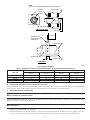
Fig. 3—Piping Installation
Table 1—Refrigerant Connections and Recommended Liquid and Vapor Tube Diameters (In.)
LIQUID
UNIT SIZE
024
030, 036
042, 048
060
Connect
Diameter
3/8
3/8
3/8
3/8
VAPOR
Tube
Diameter
3/8
3/8
3/8
3/8
Connect
Diameter
5/8
3/4
7/8
7/8
Tube
Diameter
5/8
3/4
7/8
1-1/8
Note: Tube diameters are for lengths up to 50 ft. For tubing lengths greater than 50 ft, consult your local distributor or Long-Line Application Guideline.
B.
Outdoor Units Connected to Factory-approved Indoor Units
Outdoor unit contains correct system refrigerant charge for operation with indoor unit of same size when connected by 15 ft of field-supplied or
factory accessory tubing. Check refrigerant charge for maximum efficiency. (See Procedure 10—Checking Charge.)
C.
Install Solenoid Valve in Liquid Tube
CAUTION: All models require liquid line solenoid for performance enhancement. Solenoid valve must be energized
during evacuation for complete removal.
Before making liquid tube connections, install factory-supplied solenoid valve on indoor liquid tube fitting. (See Fig. 4.) Be sure to use flare adapter
supplied with indoor coil when making connections.
CAUTION: If a field-supplied power source is needed when adding solenoid, wiring must comply with local codes and
NEC requirements.
1. Remove coil liquid connection cap and discard.
2. Mount solenoid valve on liquid tube, making sure valve flow arrow points toward indoor coil. Mount valve in any position except valve
body at top and electric coil at bottom. (See Fig. 4.) The solenoid valve is to be installed a maximum of 2 ft from indoor coil.
—3—