1
$30.00
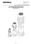
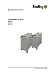
Operation and Installation Manual
Nomad Series PD-2 to PD-4
Drying and Conveying Systems
Important! Read Carefully Before Attempting to Install or Operate Equipment
ON
DEW PO INT
P RO CESS T E MPERATURE
PV
ALARMS
R
PV
SV
A
SV
A
M
R EG EN
BL OWER ON
G
L EF T BED
IN REG EN
G
PR OCESS
BL OWER ON
G
PR OCESS
H EATER ON
L EF T REG EN
H EATER ON
G
R IG HT REG EN
H EATER ON
G
HIG H T EM P
REGEN AIR
A
HIGH DEW
PO INT
A
A
ON
D R YER
ON
OFF
SYS T EM
SE Q U EN CE
SH U T D O WN
MACHINE
L OADER
O
F
F
PRO CESS
BLO WER
DIRT Y FILTER
REGEN
BLO WER
DIR T Y F ILT ER
PU SH T O
SIL EN CE
DR YING HOPPER
L OADER
OW E R
O WE R
O U TP
O U TP
M ODE
15
10
M ODE
15
10
20
20
ON
5
ON
5
25
30
0
%db("C")
MAT ERIAL
L OADING
25
30
0
O FF
O N
G
%db("ITEM")
Revision D
HIG H T EM P
PROCESS AIR
R
RIGHT BED
IN REG EN
G
Part No. A0548523
LO W
CO M PRESSED
AIR
R
M
G
OF F
O N
OF F
G
MATERIAL
LOADING
OF F
%db("ITEM")
DIRTY
F ILTER
%db("C")
DIRT Y
FILTER
Bulletin No. WH1-620B.4
Performance figures stated in this manual are based on a standard atmosphere of 59°F
(15°C) at 29.92” Hg (1,014 millibars) at sea level, using 60 hz power. Altitude is an
important consideration when specifying drying and conveying systems. AEC/Whitlock
can advise you on proper selection and sizing of systems for your operating
environment.
AEC/Whitlock is committed to a continuing program of product improvement.
Specifications, appearance, and dimensions described in this manual
are subject to change without notice.
© Copyright AEC/Whitlock and AEC, Inc. 2008
All rights reserved.
Effective 4/25/2008
Part No. A0548523
Revision D
Bulletin No. WH1-620B-4
Page 2
Nomad Series PD-2 to PD-4 Drying and Conveying Systems
Safety Considerations
AEC/Whitlock Nomad Series drying and conveying systems are designed to provide safe and
reliable operation when installed and operated within design specifications, following national
and local safety codes.
To avoid possible personnel injury or equipment damage when installing, operating, or
maintaining this equipment, use good judgment and follow these safe practices:
; Follow all SAFETY CODES.
; Wear SAFETY GLASSES and WORK GLOVES.
; Disconnect and/or lock out power before servicing or maintaining the dryer.
; Use care when LOADING, UNLOADING, RIGGING, or MOVING this equipment.
; Operate this equipment within design specifications.
; OPEN, TAG, and LOCK ALL DISCONNECTS before working on this equipment. It is a
good idea to remove the fuses and carry them with you
; Make sure the dryer and components are properly GROUNDED before switching on power.
; Do not jump or bypass any electrical safety control.
; Do not restore power until all tools, test equipment, etc. have been removed and the dryer
and conveying equipment are fully reassembled.
; Only PROPERLY TRAINED personnel familiar with the information within this manual
should work on this equipment.
Nomad Series PD-2 to PD-4 Drying and Conveying Systems
Page 3
Table of Contents
1
General Information ................................................. 7
1-1
1-2
1-3
1-4
1-5
1-6
1-7
1-8
1-9
1-10
2
Shipping Information.............................................. 13
2-1
2-2
2-3
2-4
2-5
3
Unpacking and Inspection
In the Event of Shipping Damages
If the Shipment is Not Complete
If the Shipment is Not Correct
Returns
Mechanical Installation .......................................... 15
3-1
3-2
3-3
3-4
3-5
3-6
3-7
3-8
3-9
3-10
3-11
3-12
3-13
3-14
Page 4
Models Covered
Equipment Function
Necessary Documents
Standard Features
Options
The Closed Loop Drying System
What is Desiccant?
The Process/Regeneration Cycle
Closed Loop Machine Conveying
Specifying a Drying/Conveying System
Work Rules
Positioning Your Nomad System
Drying Hopper
Installing the Sight Glass Loader
Flange Mounting Tips
Installing Material/Vacuum Tubing
Adjusting the Machine Loader Closed Loop Dry Air Take-Off
Compartment
Adjusting Sight Glass Proximity Sensor Sensitivity
Drying Hopper Loader
Installing the Pickup Probe for Hopper Loaders
Connecting Cooling Water to the Optional Aftercooler
Connecting Compressed Air
Making Electrical Connections
Checking for Proper Blower Rotation
Nomad Series PD-2 to PD-4 Drying and Conveying Systems
Table of Contents
4
Controls ................................................................... 29
4-1
4-2
4-3
4-4
4-5
4-6
4-7
4-8
4-9
4-10
4-11
4-12
4-13
4-14
4-15
5
Startup, Shutdown, and Operation ....................... 49
5-1
5-2
5-3
6
Pre-Startup Checks
Startup
Shutdown
Maintenance ............................................................ 51
6-1
6-2
6-3
6-4
6-5
6-6
6-7
6-8
7
Control Panel Indicator Lights and Switches
Process Air Dew Point Display
Process Air Temperature Controller
Machine Loader Timer
Optional Drying Hopper Loader Timer
Identifying Temperature Controller LED Indicators
Identifying Temperature Controller Keys
Setting the Process Air Temperature
Setting the Shift on Dew Point
Setting the High Dew Point Alarm
Setting the Convey Timer and Range Selection
Convey Dump Delay Setting
PLC Controller
PLC LED Indicators
Optional Seven-Day Timer
Work Rules
Servicing Process Air Filters
Servicing the Dew Point Monitor
Symptoms of Worn Desiccant
Replacing Worn Desiccant
Replacing the Process Heater
Replacing the Regeneration Heater
Restoring the E5CK Temperature Controller and Dew Point Meter
to Factory Setup
Troubleshooting ..................................................... 67
Nomad Series PD-2 to PD-4 Drying and Conveying Systems
Page 5
Charts and Figures
1
2
3
4
5
6
7
8
9
10
11
12
13
14
15
16
17
18
19
Page 6
Nomad PD-2 through PD-4 Specifications
9
Dryer Air Flow Diagram
10
Typical Nomad System with Cabinet-Style Dryer
12
Typical Machine Loader and Drying Hopper Loader Diagrams
16
Sight Glass Hopper Flange Templates
18
Machine Loader Closed Loop Dry Air Take-Off Compartment
21
Hopper Loader Flapper Detail
23
Typical Pickup Probe
24
Typical Quick-Disconnect Cable Connections
26
Typical Nomad Interface Panel
31
Typical Nomad Temperature Controller
34
Typical Nomad System Timer and Range Selection Table
36
Dump Delay Settings and Timing Configuration Chart
37
Typical Subpanel Layout
41
Typical PD2-4 Electrical Schematic, Drawings 1 and 2
42-43
Required Desiccant Amounts Per Bed
56
Display Readout for Mode Settings and Available Security Levels
Setting List for Process Temperature Controller,
Part No. A0548565
59
61-63
Setting List for Dew Point Controller, Part No. A0548565
64-65
Nomad Series PD-2 to PD-4 Drying and Conveying Systems
1
1-1
General Information
Models Covered
This manual provides instructions for installing and operating AEC/Whitlock Nomad Series
PD-2, PD-3, and PD-4 portable drying and conveying systems with WD90, WD100, WD150,
and WD225 cabinet-style dehumidifying dryers. The dryer number designation represents air
flow capacity. The carts also include insulated drying hoppers and various levels of conveying
options.
1-2
Equipment Function
Nomad Series portable drying and conveying systems are used for automatic pneumatic handling
and drying of most free-flowing, dry, pelletized, or granular materials.
AEC/Whitlock dehumidifying dryers are designed to generate heated, dehumidified air at
carefully controlled temperatures for use in closed-loop plastic drying systems. Moisture
removal from hygroscopic (moisture attracting) plastic pellets is an essential step in the
manufacture of high-quality plastic products. AEC/Whitlock dehumidifying dryers are used to
generate very low dew point air heated to a controlled temperature for drying plastic pellets and
regrind.
AEC/Whitlock Mass Flow Series drying hoppers are engineered to be used with the
dehumidifying dryers. The dryer circulates hot air through the column of plastic resin in the
drying hopper. The resin in the hopper is discharged through a slide gate in a “first in, first out”
manner. Material conveying systems convey dry material from the drying hopper to a sight glass
loader. The optional drying hopper loader conveys material from a gaylord to the drying hopper.
Nomad Series Portable Drying and Conveying systems are sized to meet the specific
requirements stated by the purchaser at the time of purchase.
Nomad Series PD-2 to PD-4 Drying and Conveying Systems
Page 7
1-3
Necessary Documents
The documents listed below are necessary for the operation, installation, and maintenance of
AEC/Whitlock Nomad carts. You can obtain additional copies from AEC, Inc. Make sure that
the appropriate personnel are familiar with these documents:
; This manual.
; The schematic and assembly drawings included in the customer information packet.
; The Customer Parts List included in the information packet.
; Operation and installation manuals for any optional controls or auxiliary equipment in the
drying system.
1-4
Standard Features
; Rugged compact cart with handle and sturdy 4” (10 cm) casters.
; Dual blower dryer with dual desiccant beds and 4-way compressed air operated valves.
; Up to 400ºF (204ºC) drying temperature range.
; Insulated drying hopper with sight glass.
; Cartridge type (two stage) air filters for all blowers.
; Integral Control Center for dryer and loading options.
; Electrical disconnect with all wiring to a common terminal point.
; PLC microprocessor control of the drying and conveying stations.
; Digital Dew Point monitor indicates dryer efficiency.
; Sequence shutdown of the dryer.
Level A – Machine Loader Only
; Sight glass loader with high efficiency centrifugal blower and adjustable convey timer.
; Cartridge type (two stage) air filters for the blower.
; Quick disconnect cable for sight glass loader material demand switch.
; Two (2) ten (10) -foot (3 m) lengths of vinyl flex hose and clamps.
; Closed loop dry air convey take-off compartment on discharge of drying hopper.
Page 8
Nomad Series PD-2 to PD-4 Drying and Conveying Systems
Level B – Drying Hopper Loader Only
; Drying hopper loader with high efficiency centrifugal blower and adjustable convey timer.
; Cartridge type (two stage) air filters for the blower.
; Quick disconnect cable for drying hopper loader material demand switch.
; Pick-up wand and ten (10) foot (3 m) length of vinyl flex hose and clamps.
; Standard take-off compartment (open loop) on discharge of drying hopper.
Level C – Both Machine Loader And Drying Hopper Loader
; Features of both level A and level B, including closed loop dry air convey take-off
compartment.
1-5
Options
Options can tailor your AEC/Whitlock Nomad system to meet the exact requirements of the
drying task being performed.
; 13X desiccant.
; Aftercoolers for high and low temperature applications.
; Seven day timer to allow programmable dryer startup.
; Audible/visual critical alarm.
; Fusing for blowers and heaters.
; Dirty Filter indicator for each individual blower.
; Proportioning valve for the drying hopper loader (Levels B and C).
; Stainless steel convey hose (Levels A and C).
Figure 1
Nomad PD-2 through PD-4 Specifications
Dryer
Hopper
Process
Model model
size
air flow
number number cu. ft. liters lbs. Kg cfm cmh
PD-2
WD90
6.0
160 200 90.8 90 153
PD-3
WD100 12.0
320 400 181.6 100 170
PD-4A WD150 12.0
320 400 181.6 150 255
PD-4B WD150 17.0
452 600 272.4 150 255
PD-4C WD225 23.0
612 800 363.2 225 382
c Level C (Machine Loader and Drying Hopper Loader)
Output
Full
temperature
Standard load
range
voltage amps c
460/3/60
24
140°-400° F (60°-204°C)
27
185°-400° F (85°-204°C) 460/3/60
38
160°-400° F (71°-204°C) 460/3/60
38
160°-400° F (71°-204°C) 460/3/60
48
160°-400° F (71°-204°C) 460/3/60
Nomad Series PD-2 to PD-4 Drying and Conveying Systems
Page 9
1-6
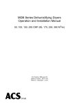
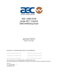
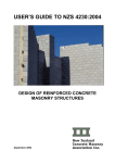
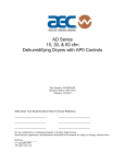
The Closed Loop Drying System
AEC/Whitlock dryers force hot, dry air through the resin in the drying hopper where the air
picks up moisture from the material and is drawn back to the dryer.
In the dryer, a desiccant bed strips moisture from the air. The dryer then re-heats dried process
air, and sends it back into the drying hopper to dry material again.
This system is a closed loop, because ambient (outside) air is never introduced into the process
air. AEC/Whitlock uses the closed loop system, because the process air is typically much
drier than ambient air, even after carrying moisture out of the plastic resin. Recycling process
air maintains drying efficiency at a consistently high level.
Figure 2
Dryer Air Flow Diagram
Page 10
Nomad Series PD-2 to PD-4 Drying and Conveying Systems
From
drying hopper
Ambient
Regen
filter
Process air
heater
Regen
bleed
Process
filter
To drying
hopper
Upper valve
Desiccant
beds
Desiccant
beds
Regen heater
Regen heater
Lower valve
Regen blower
Process blower
Nomad Series PD-2 to PD-4 Drying and Conveying Systems
Page 11
1-7
What is Desiccant?
Desiccant is a material which attracts and holds (absorbs) water from the air. AEC/Whitlock
dryers use a synthetic crystalline metal aluminosilicate desiccant blended with a clay binder and
formed beads.
Absorbed water is driven from saturated desiccant by heating it to a high temperature (reducing
desiccant capacity to hold water) and forcing air through it. This moisture removal process is
called regeneration.
1-8
The Process/Regeneration Cycle
AEC/Whitlock dryers have two desiccant beds. While one bed is on-line in the process air loop,
the other is off-line being regenerated.
When a desiccant bed is on-line, it absorbs moisture from the process air. In time, the bed
becomes saturated with moisture and needs to be regenerated. The dryer automatically redirects
the process airflow to the second bed and starts the regeneration cycle on the first bed.
During regeneration, the dryer heats air to over 500°F (260ºC) and forces it through the desiccant
bed. Moisture driven off the bed bleeds to the atmosphere.
If you measure the temperature of the air bled to the atmosphere (bleed temperature), you should
observe a rise after a period of time. This condition, bed breakthrough, indicates that the bed is
dry. At bed breakthrough, the bleed air temperature peaks between 350°F (176ºC) and 400°F
(204ºC).
The Dew Point meter measures the dew point of the process air. A properly regenerated bed
produces process air dew point of -40°F (-40ºC). This ultra-low humidity level is more than
adequate to dry plastics to as little as .003% moisture, depending on the process and material.
1-9
Closed Loop Machine Conveying
A high efficiency centrifugal blower and special designed take-off compartment provides closed
loop dry air conveying of material from the drying hopper to a sight glass loader located at the
press.
The single-station control includes a low level sensor that sends a signal to the PLC and starts
the blower and conveys material for a set amount of time. An adjustable convey timer is located
on the control panel. Once the convey time is over, the blower shuts down and starts a dump
delay time to allow material to flow into the processing machine. If a demand is still present, the
PLC starts the convey cycle over.
Page 12
Nomad Series PD-2 to PD-4 Drying and Conveying Systems
1-10 Specifying a Drying/Conveying System
Many variables were considered in the selection of your drying system, including type of
materials, residence time, throughput of the extruder or injection molding machine, ambient air
moisture and temperature, and the altitude at the processing site. If your operating environment
changes, AEC/Whitlock can advise you on necessary equipment and process time and
temperature modifications required for your system.
AEC/Whitlock can advise you on your system capabilities based on system makeup, distance,
material, and the conveying rates you select.
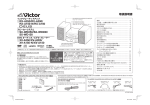
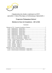
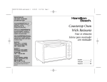
Figure 3
Typical Nomad System with Cabinet-Style Dryer
Drying hopper
loader
Machine
loader
Material
pickup
probe
Drying
hopper
Optional
aftercooler
ON
D EW POINT
PR OC ESS TEMPER ATUR E
PV
LOW
COM PRESSED
AIR
R
HIGH TEM P
PROCESS AIR
R
HIGH TEM P
REGEN AIR
SV
O
F
F
A
M
Machine
throat
A LARMS
R
PV
SV
A
M
G
RE GEN
BLOWER ON
G
LEFT BED
I N REGEN
G
LEFT REGEN
HEATER ON
G
RIGHT BED
I N REGEN
G
RIGHT REGEN
HEATER ON
G
PRO CESS
BLOW ER ON
A
G
PRO CESS
HEATER ON
A
A
ON
DR Y E R
ON
O FF
S Y S TE M
S E Q UE N CE
S HU T DO W N
MACHINE
LOADER
HIGH DEW
POINT
PRO CESS
BLOW ER
DIRTY FILTER
REGEN
BLOW ER
DIRT Y FI LTER
PU SH T O
S I LE NCE
DR YI NG HOPPER
LOADER
O WER
PO WE R
O U TP
O UT
M O DE
15
10
M O DE
15
10
20
20
ON
5
ON
5
25
30
0
%db("C")
M ATERIAL
LOADING
25
30
0
O FF
O N
G
%db("ITEM ")
O FF
O N
OFF
G
M ATERIAL
LOADING
OFF
%db("ITEM ")
DIRTY
FILTER
%db("C")
DIRTY
FILTER
Dryer
Take-off
compartment
Nomad Series PD-2 to PD-4 Drying and Conveying Systems
Page 13
2
Shipping Information
2-1
Unpacking and Inspection
You should inspect your Whitlock dehumidifying dryer for possible shipping damage. Save the
container and packing materials for re-shipment if they are in reusable condition.
Thoroughly check the equipment for any damage that might have occurred in transit, such as
broken or loose wiring and components, loose hardware and mounting screws, etc. In case of
breakage, damage, shortage, or incorrect shipment, refer to the following sections.
2-2
In the Event of Shipping Damages
Important!
According to the contract terms and conditions of the Carrier,
the responsibility of the Shipper ends at the time and place of shipment.
The Carrier then assumes full responsibility of the shipment.
; Notify the transportation company’s local agent if you discover damage.
; Hold the damaged goods and packing material for the examining agent’s inspection. Do not
return any goods to AEC, Inc. before the transportation company inspection and
authorization.
; File a claim against the transportation company. Substantiate the claim by referring to the
agent’s report. A certified copy of our invoice is available upon request. The original Bill of
Lading is attached to our original invoice. If the shipment was prepaid, write us for a
receipted transportation bill.
; Advise AEC, Inc. regarding your wish for replacement and to obtain an RMA (return
material authorization) number.
Page 14
Nomad Series PD-2 to PD-4 Drying and Conveying Systems
2-3
If the Shipment is Not Complete
Check the packing list. The apparent shortage may be intentional. Back-ordered items are noted
on the packing list. You should have:
; Nomad drying/conveying system.
; Sight glass loader.
; Material tubing.
; Bill of Lading.
; Packing list.
; Operation and Installation packet.
; Electrical schematic and panel layout drawings.
; Component instruction manuals.
Re-inspect the container and packing material to see if you missed any smaller items during
unpacking. Determine that the item was not inadvertently taken from the area before you
checked in the shipment. Notify AEC, Inc. immediately of the shortage.
2-4
If the Shipment is Not Correct
If the shipment is not what you ordered, contact the parts and service department
immediately at [847] 273-7700. Have the item and order numbers ready to expedite the return.
Hold the items until you receive shipping instructions.
2-5
Returns
Important!
Do not return any damaged or incorrect items
until you receive shipping instructions from AEC, Inc.
Nomad Series PD-2 to PD-4 Drying and Conveying Systems
Page 15
3
Installation
3-1
Work Rules
The installation, operation, and maintenance of this equipment must be conducted in accordance
with all applicable work and safety codes for the installation location. This may include, but is
not limited to, OSHA, NEC, CSA, and any other local, national, and international regulations.
•
Read and follow these operating instructions when installing, operating, and maintaining
this equipment. If the instructions become damaged or unreadable, additional copies are
available from AEC/Whitlock.
•
Only qualified personnel familiar with this equipment should work on or with this dryer.
•
Work with approved tools and devices.
•
Disconnect the electricity before maintenance or service. If the dryer is installed with a
power cord that can be unplugged, unplug it. If the dryer is permanently wired to a power
main, a fused power disconnect must be installed to allow the disconnect to be locked in
the OFF position. Open and lock out the disconnect installed in the control enclosure.
3-2
Positioning Your Nomad System
The Nomad system was designed to be wheeled into place. The entire assembly is mounted on a
rugged, compact frame with an integral handle. The cart is equipped with sturdy, 6” (15 cm)
heavy duty casters, two locking and two swivel.
Caution!
Use caution and observe safety rules when placing your cart!
Page 16
Nomad Series PD-2 to PD-4 Drying and Conveying Systems
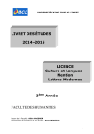
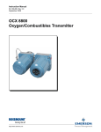
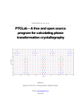
Figure 4
Typical Machine Loader and Drying Hopper Loader Diagrams
Dryer
Drying hopper
ON
D E W P%Odb("
I NTITEM"
DIS PLA
Y
)
P R O C E S %db("
S T E ITEM"
M PE RATUR
E
)
PV
SV
A
M
O
F
F
A LARM S
% db(" ITEM" )
L OW
%db("C" ) CO MPRES SED
AIR
% db(" ITEM" )
HI GH TEMP
%db("C" ) P ROCESS AIR
PV
SV
A
% db(" ITEM" )
HI GH TEMP
%db("C" ) RE GE N AIR
M
%db(" ITEM" )
RE GE N
%db(" C") BL OWER ON
%db(" ITEM" )
P ROCE SS
%db(" C") BLO WER ON
%db(" ITEM" )
LEFT BED
%db(" C") I N REGE N
%db(" ITEM" )
P ROCE SS
%db(" C") HE ATER ON
% db(" ITEM" )
HI G H DEW
%db("C" ) P OI NT
%db(" ITEM" )
L E FT REGE N
%db(" C") HE ATER ON
%db(" ITEM" )
%db(" ITEM" )
RI GHT BE D
%db(" C") I N REGE N
%db(" ITEM" )
RI G HT RE GEN
%db(" C") HE ATER ON
Sight
glass
loader
Quickdisconnect
cable
CONTROL
P O WER
C O NV E
STATIO
%Ydb("
ITEM" ) N # 1
C ON VE%
Y db("
S TATION
ITEM" ) #2
% db(" ITEM" )
%db("ITEM ")
OUTPOWER
OUTPOWER
M ODE
M ODE
15
10
15
10
20
5
S TATION
30
0
20
5
25
O FF
25
30
0
OF F
#1
% db(" ITEM" )
ON
ON
%db("C" )
S TATION
#2
%db("ITEM ")
%db("C" )
MATE RIAL
L OADI NG
MATERIAL
L OADING
Machine
loader
conveying
blower
Machine throat
Material Conveying Legend
Dry material
Machine
loader
conveying
filter
Closed loop convey
(pressure side)
Material
take-off
compartment
Closed loop convey
(vacuum side)
Machine Loader Diagram
Levels A and C
Drying
hopper
loader
Dryer
Drying hopper
ON
D E W P O I NT DIS PLA Y
P R O CE S S TE M PE RATUR E
%db("ITEM")
A LAR MS
%db(" ITEM" )
PV
% db(" ITEM" )
L OW
%db("C" ) CO MP RES SED
AIR
PV
SV
A
M
O
F
F
% db(" ITEM" )
HI GH TEMP
%db("C" ) P ROCES S AIR
SV
A
% db(" ITEM" )
HI GH TEMP
%db("C" ) RE GE N AIR
M
%db("ITEM")
RE GE N
%db(" C") BL OWER ON
% db(" ITEM" )
P ROCES S
% db(" C" ) BLO WER ON
%db("ITEM")
LE FT BED
%db(" C") I N RE GEN
% db(" ITEM" )
P ROCES S
% db(" C" ) HE ATE R ON
% db(" ITEM" )
HI G H DEW
%db("C" ) P OI NT
%db("ITEM")
L E FT RE GE N
%db(" C") HE ATE R ON
% db(" ITEM" )
%db("ITEM")
R I G HT BE D
%db(" C") I N R E G EN
%db("ITEM")
R I G H T REG E N
%db(" C") H E A T ER O N
CO NTROL
P OWE R
CO N V E Y STA TION # 1
C O N V E Y S TATIO N #2
%db("ITEM")
%db(" ITEM" )
% db(" ITEM" )
POWER
OUT
%db(" ITEM" )
OUTPOWER
MODE
M ODE
15
10
15
10
20
5
O FF
ON
20
5
25
30
0
S TATION
#1
25
30
0
OF F
ON
S TATI ON
#2
% db(" ITEM" )
%db(" ITEM" )
% db(" C" )
MATE RIAL
L OADI NG
% db(" C")
MATE RIAL
L OADI NG
Pickup
wand
Drying
hopper
loader
conveying
blower
Material Conveying Legend
Convey material
Convey vacuum side
Drying Hopper Loader Diagram
Drying
hopper
loader
conveying
filter
Levels B and C
Nomad Series PD-2 to PD-4 Drying and Conveying Systems
Page 17
3-3
Drying Hopper
Removing the Rust Inhibitor
Rust preventative has been applied to internal unfinished surfaces. Remove rust inhibitor
before using the drying hopper.
Using a non-water based degreasing agent, clean all inside surfaces of the drying hopper. Allow
components to dry thoroughly.
Inspect the inside of the drying hopper for loose connections, foreign objects, or a blocked
diffuser.
Air Trap Considerations
AEC/Whitlock’s exclusive air trap assembly in the top of the drying hopper prevents ambient air
from contaminating the material being dried.
; Keep the material level at the mid point of the air trap for maximum efficiency.
; Use a hopper loader or vacuum conveying system to maintain the proper material level.
3-4
Installing the Sight Glass Loader
Levels A and C
; Sight glass loaders use flange mountings. See Figure 5 on Page 18 for sight glass flange
templates. You can mount the material receiver hopper directly to the processing machine by
cutting a hole in the machine bin lid and fastening the receiver to it. The material receiver
mounting flange mates with existing AEC/Whitlock equipment and uses the same mounting
holes as previous AEC/Whitlock models.
; Complete the vacuum and material tubing from the take-off tubes located on the Nomad cart.
See Section 3-6 on the following page for information on installing material/vacuum tubing.
; Connect the quick disconnect cable for the demand sensor to the Nomad cart. See Figure 9
on Page 26 for more information.
Page 18
Nomad Series PD-2 to PD-4 Drying and Conveying Systems
Figure 5
Sight Glass Hopper Flange Templates
Models SGV011, SGV012
Optional Models SGV031/032
5.50"
14 cm
2.50"
6 cm
1.25"
3 cm
4.00"
10 cm
1.25"
3 cm
2.00"
5 cm
0.28" (9/32") hole
(7 mm)
(4 places)
2.75"
7 cm
0.28" (9/32") hole
(7 mm)
(4 places)
2.50"
6 cm
7.00"
18 cm
5.50"
14 cm
2.75"
7 cm
3.50"
9 cm
2.00"
5 cm
2.125 (2 1/8") hole
(5.5 cm)
4.00"
10 cm
3.50"
9 cm
3.00" (7.75 cm) hole
7.00"
18 cm
3-5
Flange Mounting Tips
; Run a bead of silicone sealant around the mounting flange before seating the vacuum hopper.
This makes a better seal.
; Use rivets to mount the hopper. Nuts and bolts can loosen, fall off, and damage process
equipment.
; Check across the mounting flange with a bubble level. A level installation is important for
proper hopper dump.
; Properly ground all sight glass loaders and vacuum hoppers.
3-6
Installing Material/Vacuum Tubing
Note: System capacity is directly affected by the pressure drop in the overall system, such as
number of material line bends, footage of pipe, Y-tubes, T-tubes, etc.
Use the minimum effective amount of vinyl flex hose to maximize material line efficiency. Keep
material lines as straight as possible.
Important!
Vacuum leaks anywhere in your system reduce capacity.
Nomad Series PD-2 to PD-4 Drying and Conveying Systems
Page 19
; Vacuum leaks anywhere in the system reduce system capacity.
; Keep the number of material tube bends to a minimum for maximum system capacity.
; Use long radius tube bends on material lines.
; Keep the total footage of material conveying flex hose to a minimum. Long flex hose
material runs reduce system capacity.
; Support tubing about every ten feet with straps, pipe hangers, or brackets.
; Tube joints must be rigid to prevent vacuum or material leaks.
; Cut tube ends square and chamfer edges smooth. Use a fixed band saw or power miter
saw when making cuts. You can use a tubing cutter on aluminum tubing; for cutting stainless
steel, use a saw with a carbide or diamond-impregnated saw blade. Chamfer stainless steel
edge cuts with a die grinder or a hardened rasp file.
; Clean all tubing after cutting and before assembly. Run a rag dampened in a non-volatile
cleaning solvent through all tubing and couplers to remove sediment from shipping or
cutting. Run a quantity of low-grade material through new lines to remove any remaining
sediment, and discard the material immediately.
; Tube ends must butt together inside couplers.
; Tighten tube coupler nuts from the center outward to create a tight seal and allow proper
contact of the internal grounding strip.
; Each material tubing run must maintain a continuous ground through the tubing and
couplers, from pickup point to vacuum hopper. Ungrounded flexible hoses should have
ground wires wound around the outside.
; If you must cut bends, cut the straight section and allow enough straight length for complete
insertion into a coupler.
; You can attach a quick-change or standard tube coupler to vinyl flex hose by inserting a stub
of hard tube into the hose and securing it with a hose clamp. Make sure that enough tube
extends from the hose to properly install the quick-change or coupler. Apply clear silicone
caulk around adjoining tube seams for exterior bolted couplers.
; If you use stainless flexible material hose, the material flow must be in the same direction as
the arrows on the hose. Material direction is not critical with vinyl flex hose.
Page 20
Nomad Series PD-2 to PD-4 Drying and Conveying Systems
3-7
Adjusting the Machine Loader Closed Loop Dry
Air Take-Off Compartment
Levels A and C
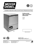
The FCO-1.5MD model fast take-off compartment has an adjustable inner tube fitted to the fixed
outer tube. A hold-down screw on the outer tube locks down the adjustable inner tube. Loosen
the screw to adjust the inner tube.
Vary the distance of the indicator knob from the outer collar (See Figure 6) to control the flow of
material to be conveyed. Adjust the inner tube so that the inside edge of the vertical knob
touches the outer collar. This position is the minimum and factory-recommended setting. The
minimum and factory setting should adequately meet the throughput requirements on
Nomad cart systems.
For higher flow rates, increase the distance by pulling the adjustable tube away until you get the
flow rate you want. The maximum amount of material should be conveyed when the adjustable
inner tube is pulled all the way out.
Note: This condition may cause the flow to be unsteady, and
eventually may plug up the line.
Along with the take-off adjustment, take special care when setting the convey time:
•
Too short of a time shortens the service life of the blower.
•
Too long of a convey time causes material to back up in the convey line, which could lead
to plugging.
Suggested convey time is a minimum of five (5) seconds and a maximum of twelve (12)
seconds.
Basic Tips
Every material has different conveying characteristics because of factors such as bulk density
and particle size. Some material is easier to flow than others. That is why the inner tube is
adjustable to give you the flexibility to control how much material you want to convey.
1. When adjusting the inner tube, always adjust from the inside out. Start from the tube
positioned all the way in (minimum setting), then slowly pull the inner tube out until the
distance from the outer edge to the indicator knob is one eighth of an inch (1/8” / 3 mm).
This is the eighth-inch (1/8” / 3 mm) setting.
Nomad Series PD-2 to PD-4 Drying and Conveying Systems
Page 21
If higher rates are required, pull the tube out in increments of one eighth of an inch (1/8” /
3 mm). Check the rate. If you still require a higher flow rate, repeat these procedures to
go to the next setting.
Important!
Never set the inner tube all the way out to start with the maximum flow rate!
2. Check the flexible hose used for conveying material from the FCO to the sight glass
loader inlet. Make sure that the hose is straight down from the bend to the inlet. If there
are any loops cut the hose to the right length to remove the bends.
The hose lengths are cut at factory to ten feet (10’/3 m); but if the hose is too long, cut it
to the right length.
3. Every time you change the material make sure you:
•
Purge all the material in the line.
•
Adjust the inner tube all the way in. (Factory recommended setting)
•
Slowly adjust by one eighth of an inch (1/8” / 3 mm) increments if you want a higher
throughput.
The distance is measured from the inside edge of the indicator knob to the outer edge of
the collar on the take-off compartment. Adjust the inner tube out in the increments of one
eighth of an inch (1/8” / 3 mm) until you get the rate you want.
If Material is Not Conveying or the Line Plugs Up…
1. Make sure the inner tube is not set beyond the outer limit, the five-eighths inch (5/8” /
16 mm) setting:
•
Adjust the inner tube to a reduced convey flow setting.
2. Make sure that the flex connection to the machine hopper inlet is straight, without any
bends:
•
Trim the hose length just enough to reach the machine hopper.
3. Make sure the convey time is not set too high:
•
Page 22
Lower the convey time.
Nomad Series PD-2 to PD-4 Drying and Conveying Systems
Figure 6
Machine Loader Dry Air Closed Loop Take-Off Compartment
Indicator
knob
Hold-down
screw
Hose
from
blower
Material
outlet
Adjustable
inner tube
FCO-1.5MD
Outer
tube
3-8
Adjusting Sight Glass Proximity Sensor
Sensitivity
You can adjust the sensitivity of the material level proximity sensor in the sight glass. The
factory setting is correct for most applications. The sensor is factory-installed to the frame;
however, you should install the sensor at the material level height you want.
When adjusting, fill the glass and verify that the sensor detects your material. The LED on the
switch goes out when it detects material.
For increased sensitivity, turn the potentiometer clockwise.
For decreased sensitivity, turn the potentiometer counterclockwise.
3-9
Drying Hopper Loader
Levels B and C
; The drying hopper loader may have been shipped loose. Mount the drying hopper loader to
top cover of drying hopper. The drying cover has the appropriate bolt holes supplied to
mount the vacuum hopper. See Section 3-5 on Page 18 for mounting tips.
Nomad Series PD-2 to PD-4 Drying and Conveying Systems
Page 23
; Complete the vacuum tubing from the filter cartridge to the vacuum inlet tube located on top
of the vacuum receiver. See Section 3-6 on Page 18 for recommendations.
; Install the pickup probe. See Section 3-11 on Page 23 for pickup probe installation
information.
; Connect the quick disconnect cable for the demand switch to the Nomad cart.
Figure 7
Hopper Loader Flapper Detail
Page 24
Nomad Series PD-2 to PD-4 Drying and Conveying Systems
Drying hopper
loader
Level demand
switch assembly
Flapper
Nomad Series PD-2 to PD-4 Drying and Conveying Systems
Page 25
3-10 Installing the Pickup Probe for Hopper Loaders
Pickup probes are used to empty gaylords or bulk material containers located beside the
processing machine. The VacTrac conveying system can use horizontal take-offs or vertical
pickup probes (or a combination of the two) to supply material to the vacuum hoppers.
; For maximum conveying rates, locate the supply container near the vacuum hopper.
; Connect the pickup probe to a vacuum hopper material inlet tube with a minimum amount of
tubing, bends, and flex hose.
; Secure the flex hose at the probe and the material inlet with hose clamps. Be sure to avoid
loops and kinks, and install grounding wire around the outside of flex hose to prevent static
built-up. Make sure you ground both ends of the grounding wire.
; Put the pickup probe in the material supply. The burrowing action of the probe provides a
steady flow of material.
; To vary the convey rate, cover or open the vent holes on the pickup probe as needed with the
inlet tube.
; If your material bridges frequently and triggers No-Convey alarm conditions, you should
consider using a gaylord tilter or tilter/jogger to supply a steady stream of material to your
VacTrac system.
Figure 8
Typical Pickup Probe
A0536903
Vent
holes
Page 26
45º
Nomad Series PD-2 to PD-4 Drying and Conveying Systems
3-11 Connecting Cooling Water to the Optional
Aftercooler
High temperature applications (300°F to 400°F / 148°C to 204°C) require aftercoolers to cool
moist air returning to the dryer from the drying hopper. An aftercooler cools the return air by
100°F (38°C); this maintains dryer efficiency and condenses unwanted plasticizers from the
airstream. Aftercoolers are also required in extremely low temperature applications.
Installing Water Lines
•
Use the ½” (about 13 mm) brass pipe nipples for water line connections. Inlet and outlet
line positions do not matter.
•
Make sure you grip the nipple tightly when attaching a fitting. Doing so prevents damage
to the soft copper coils. You should make connections with flexible hose to allow removing
the coil assembly for cleaning.
•
The aftercooler is designed to utilize either tower or city water as warm as 85ºF (29ºC).
Recommended flow rate is one to three (1 to 3) gallons per minute (4 to 11 liters per
minute).
3-12 Connecting Compressed Air
Note: Connect compressed air to the dryer before operation.
Caution!
Excessive air pressure damages the neoprene
components of the air distribution valve.
•
Connect to a clean, dry, lightly lubricated source of 80 psi (551 kPa/5.51 bars)compressed
air.
•
A pressure gauge and regulator are recommended components of your plant air supply.
•
Connect the air supply using a ¼” NPT fitting.
The compressed air indicator switch prevents the dryer from starting without an 80 psi (551
kPa/5.51 bars) air supply. If the air supply drops to below 60 psi (413 kPa/ 4.13bars) during
operation, the dryer shuts down until at least 80 psi (551 kPa/5.51 bars) is restored.
Nomad Series PD-2 to PD-4 Drying and Conveying Systems
Page 27
3-13 Making Electrical Connections
; Fulfill all national, state, and local safety and electrical code requirements.
; Connections should be made by a qualified electrician.
; Make sure all electrical connections are tight.
; Connect main power to the dryer at the disconnect or terminals in the upper right corner of
the control enclosure.
; Install a fused disconnect with a lockout feature in the power main leading to the dryer.
; The power drop must include a ground wire.
; Make sure quick disconnect cables are connected at the junction boxes on the sight glass
loader (Machine Loader) and the optional vacuum hopper (drying hopper loader).
Figure 9
Typical Quick Disconnect Cable Connections
MACHINE
LOADER
DRYING HOPPER
LOADER
! WARNING !
Proper grounding of the main power line is critical!
Page 28
Nomad Series PD-2 to PD-4 Drying and Conveying Systems
3-14 Checking for Proper Blower Rotation
Three-Phase Models
The blower rotates properly when air flows from the delivery outlet and a vacuum is felt on the
blower inlet.
Caution!
In three-phase models, incorrect phasing of power leads
can cause backward rotation of blower motors
and CONTAMINATION OF THE DESICCANT!
Always check blower rotation before putting material in the drying hopper!
If the three-phase blower rotates improperly, reverse any two wires at the fused disconnect
outside the dryer or at the disconnect/terminal in the control enclosure. This assures that the
blower rotates in the proper direction.
Nomad Series PD-2 to PD-4 Drying and Conveying Systems
Page 29
- Notes -
Page 30
Nomad Series PD-2 to PD-4 Drying and Conveying Systems
4
4-1
Controls
Control Panel Indicator Lights and Switches
Rocker Switches
System ON/OFF Rocker Switch
Press the ON/OFF rocker switch energizes or de-energizes control power to the indicator panel,
allowing separate control of the dryer and conveying systems.
Dryer ON/Sequence Shutdown Rocker Switch
Press the ON/Sequence Shutdown rocker switch to start the dryer. Move this switch to the
Sequence Shutdown position to turn off the process heaters, finish the regeneration cycle and
then turn off the dryer.
Machine Loading ON/OFF Rocker Switch
Press the ON/OFF rocker switch to start or stop the machine loader conveying system.
Optional Drying Hopper Loader ON/OFF Rocker Switch
Press the ON/OFF rocker switch to start or stop the Drying Hopper loader conveying system.
Optional Alarm Silence Rocker Switch
Press the Alarm Silence switch to silence the horn when a high temperature alarm activates. The
alarm repeats every five minutes until the problem causing the alarm condition is cleared.
Indicating Lights
Regen Blower On Light
The Regen Blower On indicator lights when the regeneration blower energizes.
Left Bed In Regen Light
The Left Bed In Regen LED lights when the left bed is in regeneration.
Left Bed Heater Light
The Left Bed Heater indicator lights when the left bed regenerates and is in the heat-up portion
of the regeneration cycle.
Nomad Series PD-2 to PD-4 Drying and Conveying Systems
Page 31
Right Bed In Regen Light
The Right Bed In Regen LED lights when the right bed is in regeneration.
Right Bed Heater Light
The Right Bed Heater indicator lights when the right bed regenerates and is in the heat-up
portion of the regeneration cycle.
Process Blower On Light
The Process Blower On indicator lights when the process blower energizes.
Process Heater On Light
The Process Heater On indicator lights when the process air heater is energized.
Low Compressed Air Light
The Low Compressed Air alarm indicator lights when the dryer compressed air supply drops
below 60 psi (413kPa/ 4.13 bars). Upon loss of compressed air, the pressure switch opens and
sends a signal to the PLC controller to shut down dryer operation. Dryer operation automatically
resumes when 80 psi (551 kPa/ 5.51 bars) air is restored.
High Temp Process Air Light
The High Temp Process Air alarm indicator lights when the temperature at the process air
thermocouple is above the high alarm set value. Upon high temperature alarm condition the
process heaters turn off, the process blower remain on.
The alarm mode and value are factory-set to track 25º above the process set point. The alarm
value is an upper-limit deviation above the process set point. When the temperature at the
process thermocouple returns to within the acceptable range, the alarm output de-energizes and
all heaters turn on again automatically.
High Temp Regen Air Light
The High Temperature Regen Air alarm indicator lights when the thermostat above the
regeneration heater assembly senses an abnormally high temperature.
The regeneration heaters shut down until the temperature falls below the alarm point. The
regeneration blower continues to run for cooling the heaters and desiccant bed. The alarm
condition clears when the temperature drops below the thermostat setpoint. The heaters reenergize automatically.
High Dew Point Light
The High Dew Point alarm indicator lights when the process air delivery dew point exceeds a
dew point of -10°F (-23°C).
Page 32
Nomad Series PD-2 to PD-4 Drying and Conveying Systems
Material Loading Light
The Material Loading indicator lights when material is being conveyed.
Optional Dirty Filter Light
If installed, the Dirty Filter alarm indicator lights when the pressure differential across the
process, regeneration and conveying air return filter exceeds the pressure switch setting. Service
the filter when this indicator lights. The indicator and the alarm condition clears after you service
and reinstall the filter.
Figure 10
Typical Nomad Interface Panel
Nomad Series PD-2 to PD-4 Drying and Conveying Systems
Page 33
DEW POINT
PROCESS TEMPERATURE
PV
ALARMS
PV
SV
R
SV
AT
R
HIGH TEMP
PROCESS AIR
R
HIGH TEMP
REGEN AIR
AT
G
REGENERATION
BLOWER ON
G
PROCESS
BLOWER ON
A
HIGH DEW
POINT
G
LEFT BED
IN REGEN
G
PROCESS
HEATER ON
A
PROCESS
BLOWER
DIRTY FILTER
G
LEFT REGEN
HEATER ON
A
REGEN
BLOWER
DIRTY FILTER
G
RIGHT BED
IN REGEN
G
RIGHT REGEN
HEATER ON
MACHINE
LOADER
ON
DRYER
ON
OFF
SYSTEM
SEQUENCE
SHUTDOWN
PUSH TO
SILENCE
DRYING HOPPER
LOADER
POWER
OUT
POWER
OUT
MODE
15
10
MODE
15
10
20
20
ON
5
ON
5
25
30
0
G
MATERIAL
LOADING
A
DIRTY
FILTER
25
30
0
OFF
ON
Page 34
LOW
COMPRESSED
AIR
OFF
ON
OFF
G
MATERIAL
LOADING
A
DIRTY
FILTER
OFF
Nomad Series PD-2 to PD-4 Drying and Conveying Systems
4-2
Process Air Dew Point Display
The Dew Point display indicates the current process air delivery moisture content. The display
uses a microprocessor-based controller for reading dew point air temperature. The controller is a
modular, self-contained removable unit in the mounting housing. All parameters are factory-set
and adjusted; no field adjustment to the internal controls is necessary. The high dew point alarm
is also factory adjusted.
4-3
Process Air Temperature Controller
AEC/Whitlock dryers use a microprocessor-based PID temperature controller for maintaining
process air temperature. The controller is a modular, self-contained unit you can remove from
the mounting housing. All parameters except for the process air set point is factory set and
adjusted; no field adjustment to the internal controls is necessary.
4-4
Machine Loader Timer
AEC/Whitlock Nomad systems use a solid-state analog-set 1/16 DIN machine loading timer. It
has a large dial for setting convey times and has several timing modes available.
4-5
Optional Drying Hopper Loader Timer
If installed, AEC/Whitlock Nomad systems use a solid-state analog-set 1/16 DIN drying hopper
loading timer. It has a large dial for setting convey times, and has several timing modes.
4-6
Identifying Temperature Controller LED
Indicators
—— PV ——
Process Value Numeric LED
During normal operation, the process value (PV) numeric LED indicator displays the process
temperature at the To Process thermocouple. It also lists parameters during setup and error
messages if any errors occur.
—— SV ——
Set Value Numeric LED
During normal operation, the set value (SV) numeric LED indicator displays the process set
point you selected for the dryer. The dryer then maintains this set point temperature. This LED
indicator also displays parameter and pre-set function values during setup.
Nomad Series PD-2 to PD-4 Drying and Conveying Systems
Page 35
OUT1 - Lit when control output 1 turns on.
The OUT indicator lights when the controller signals the process heaters to be energized.
OUT2 - Lit when control output 2 turns on.
Not used in this application.
MANU - Lit when the manual operation mode is being used.
STOP - Lit when control operation has been stopped.
Not used in this application.
RMT - Lit during remote operation.
Not used in this application.
AT - Flashes during auto-tuning.
SUB1 Lit when the output function assigned to auxiliary output 1 turns on.
The SUB1 indicator lights when the process temperature exceeds the set point temperature by
more than the alarm deviation value. This alarm output de-energizes the heaters. Heaters reenergize when the temperature falls within the acceptable range.
4-7
Identifying Temperature Controller Keys
Display Key
This key shifts the display to the next set of parameters. Then, the menu screen displays.
Down Key
The Down arrow key lets you lower the process air set point temperature. During setup, it lets
you decrease the value of the parameter displayed on the set point LED readout.
Up Key
The Up arrow key lets you raise the process air set point temperature. During setup, it lets you
increase the value of the parameter displayed on the set point LED readout.
AT
Auto-Tune Key
Hold down for two seconds to initiate auto-tune. Repeat to cancel.
Page 36
Nomad Series PD-2 to PD-4 Drying and Conveying Systems
Figure 11
Typical Nomad Temperature Controller
PV
SV
OUT1
OUT2 MANU STOP RMT
AT
SUB1
AT
E5CK
4-8
Setting the Process Air Temperature
To change the process air temperature set point with the dryer running:
Press
to raise the set point to the temperature you want.
Press
to lower the set point to the temperature you want.
Press the
AT
Auto-tune key to initiate auto-tuning.
4-9 Setting the Shift on Dew Point
Nomad dryers shift air flow from the on-line desiccant bed to the regenerated desiccant bed,
based on actual dew point demand, not fixed time cycles. After the off-line bed regenerates, the
PLC controller waits for a high dew point signal from the process air dew point controller before
switching beds. The PLC controller has a four (4) -hour timer override if it does not receive a
signal from the dew point control.
Nomad Series PD-2 to PD-4 Drying and Conveying Systems
Page 37
Set the shift on dew point set point to the highest process air moisture content you want to
allow before the dryer shifts air flow to the regenerated desiccant bed. The dew point
controller is set at the factory for -20ºF (-29ºC).
To change the dew point setting, press the
to the shift point you want.
Up Arrow and
Down Arrow keys
4-10 Setting the High Dew Point Alarm
The high dew point alarm is factory set for -10ºF (-23ºC). The high dew point alarm will
energize the “High Dew Point” light. Entering the Level 1 operating parameter changes the high
dew point alarm setting.
1. Press
once (keep the pressure on the button for about 1-1.5 seconds) in order to
switch between modes. Level 0 displays.
2. Press
to display Level 1. Lu-1 displays.
3. Press
once more for about one to one and a half seconds. Now use short presses
until AL-1 displays.
4. Press
and
5. Press
for about one to one and a half seconds. Level 1 displays.
6. Press
until Level 0 displays.
7. Press
for about one to one and a half seconds to go to Operating mode.
to set the higher or lower value for the high dew point alarm.
Note: The E5CK controller has several levels of securities to lock out access to parameters and
menu settings. If the controller will not allow you to change settings, see Section 6-8 on
Page 60 to set the E5CK security to access the function you need.
4-11 Setting the Convey Timer and Range Selection
Set the convey timer by rotating the large dial to the convey time you want. The time units is
factory set for seconds. The time range is factory set to 0-30 seconds. The operating mode is set
to A for on-delay. Remove the black cover to gain access to the time unit selector and the time
range selector.
Page 38
Nomad Series PD-2 to PD-4 Drying and Conveying Systems
The rotary selector switches are located under the dial. Turn the lower right rotary selector
switch to set the time unit selection. By turning the screw, the time units will cycle between
seconds, minutes, hours, and ten (10) hours.
Turn the lower left rotary selector switch to set the time range selection. The dial digits appear in
the windows around the time setting knob. The dial digits change when different time ranges are
selected. Time ranges are 0-0.5, 0-1, 0-5 and 0-10.
Figure 12
Typical Nomad System Timer
Power indicator
(green LED)
Flashes when
timer operates,
lit when timer
stops operating
Operating mode
display window
POWER
OUT
OFF
Output indicator
(red LED)
Operation mode
selector; factoryset "A" On-Delay
Time setting knob
MIN
Scale range
display window
Time range
selector
Time unit
display window
Time unit selector
Range Selection Table
Time
range
1.2
3
12
30
0
sec(onds)
0.05 to 1.2
0.3 to 3
1.2 to 12
3 to 30
Instantaneous output
Time units
min(utes)
hrs (hours)
0.12 to 1.2
0.12 to 1.2
0.3 to 3
0.3 to 3
1.2 to 12
1.2 to 12
3 to 30
3 to 30
10h (ten hours)
1.2 to 12
3 to 30
12 to 120
30 to 300
4-12 Convey Dump Delay Setting
After the convey timer times out, the PLC will start a dump delay before allowing the convey
cycle to start again. The dump delay time is adjusted by jumper inputs into the PLC. The yellow
jumpers are wired into yellow terminal blocks located on the sub-panel. For example, a ten (10)
second dump delay would have a yellow jumper wired from a number four terminal to number
33 (PLC I/18) terminal. Terminals number 31 and 32 would have no jumpers. Dump delay time
is the same for both convey stations.
Nomad Series PD-2 to PD-4 Drying and Conveying Systems
Page 39
Figure 13
Dump Delay Settings
Conveying
dump delay
timing inputs
31
Jumpers
18 GA
Yellow
Terminals
for jumpers
32
33
31
32
33
1/16
1/17
1/18
Yellow
4 for jumper
terminals
4
See Timing Configuration Chart
below for timing configurations
1/19
PLC
Timing Configuration Chart
1/16
0
0
0
0
1
1
1
1
1/17
0
0
1
1
0
0
1
1
1/18
0
1
0
1
0
1
0
1
Dump delay preset
5 seconds
10 seconds
15 seconds
20 seconds
25 seconds
30 seconds
35 seconds
40 seconds
Note: Jumpers are provided for setting the dump delay time. Use this chart to remove or add
jumpers and set the dump delay time you want.
4-13 PLC Controller
The PLC controller uses an Allen-Bradley programmable logic controller (PLC). This “brick”type controller has 32 I/O points: twenty (20) inputs and twelve (12) outputs, all inputs and
outputs are 115 VAC.
All programming and logic is factory-installed on an EEPROM chip and cannot be modified. A
battery backup retains programming if power fails. Battery life is five (5) years at room
temperature.
If the alarm indicator blinks intermittently, replace the battery within one week.
Page 40
Nomad Series PD-2 to PD-4 Drying and Conveying Systems
4-14 PLC LED Indicators
Input LED Indicators
System Start/Sequence Shutdown (I/0)
When ON, activates the operation of the dryer portion.
Compressed Air Input (I/1)
This input point is jumpered because this unit does not contain the feature thereof.
Process Blower Enable (I/2)
Confirms the operation of the process blower.
Bed Switch Set Point Input (I/4)
Since this is strictly a time base unit, this device is jumpered so that it constantly yields power to
this input point.
High Regen Temp Alarm, Right Bed (I/5)
When OFF, indicates a situation of a temperature exceeding the set level in the right regen bed.
High Regen Temp Alarm, Left Bed (I/6)
When OFF, indicates a situation of a temperature exceeding the set level in the right regen bed.
Universal Alarm Input (I/7)
Not used here.
High Process Temp Alarm (I/8)
When ON, sends the information to the PLC to be used later in forming alarm procedure.
Push To Silence (I/9) (Optional)
When the existing rocker switch is pressed, the audible horn will be silenced and flashing strobe
will be turned off. Also, it serves as an alarm acknowledgment.
Machine Loader Power On (I/10)
When ON, enables the Machine Loader conveying process.
Machine Loader Demand Proximity Switch (I/11)
When ON, indicates a demand in the sight glass loader; this activates the conveying cycle.
Nomad Series PD-2 to PD-4 Drying and Conveying Systems
Page 41
Machine Loader Loading Complete (I/12)
An input coming from a conveying timer that indicates when the conveying time is complete.
Drying Hopper Convey Power On (I/13)
Optional
When ON, enables the Drying Hopper conveying process.
Drying Hopper Convey Demand Reed Switch (I/14)
Optional
When ON, indicates a demand in the Hopper Loader; this activates the conveying cycle.
Convey To Process Loading Complete (I/15)
Optional
An input coming from a conveying timer that indicates when the conveying time is complete.
Dump Relay Jumper Setup (I/16, I/17, I/18)
These inputs determine the dump delay time period—a period that follows conveying period.
Output LED Indicators
Blower On (O/0)
The Blower On indicator lights when the blower energizes.
Process Heater Enable (O/2)
The Process Heater Enable activates the process heater. The indicator lights when the process
heater is energized. This condition occurs when no blower failures or high temperature
conditions exist.
Right Bed Regeneration Output (O/5)
The right Bed Regeneration Output activates the right bed regeneration indicator lights when
the right bed regenerates. When this indicator is off, the left bed is energized.
Left/Right Regen Heater Output (O/3, O/4)
The Regen Heater Output indicator lights when the indicated bed regeneration heater
energizes.
High Regen Temp Alarm (O/6)
When ON, indicates a high regen temp condition in either the left or right bed.
Page 42
Nomad Series PD-2 to PD-4 Drying and Conveying Systems
Alarm Horn Output (O/7)
Optional
The Alarm Horn Strobe Output indicates a high process temperature condition and optional
critical low level at the drying hopper.
Machine Loader Convey Blower (O/8)
When ON, the Machine Loader convey blower contactor is energized.
Drying Hopper Convey Blower (O/9)
Optional
When ON, the Drying Hopper convey blower contactor is energized.
Machine Loader Convey Timer (O/10)
When ON, the convey timer starts timing a loading process.
Drying Hopper Convey Timer (O/11)
Optional
When ON, the convey timer starts timing a loading process.
Status LED Indicators
Power
The Power indicator lights when the PLC receives 115V control power.
Run
The Run indicator lights when the PLC executes the program in normal conditions.
Fault
The Fault indicator lights when the PLC program has a problem or failure condition.
Force
The Force indicator is not used.
Nomad Series PD-2 to PD-4 Drying and Conveying Systems
Page 43
Figure 14
Typical Subpanel Layout
1
2
3
4
5
6
7
8
5
6
OU T
9
IN
P OW ER
R UN
FAULT
F ORCE
1
2
3
4
TERMINALS
Page 44
Nomad Series PD-2 to PD-4 Drying and Conveying Systems
Figure 15
Typical PD2-4 Electrical Schematic, Drawing 1
L1
1L1
BRANCH FUSING
(OPTIONAL)
1FU
1L1
2L1
L2
1L2
1L2
2L2
1T2
L3
1L3
1L3
2L3
1T3
1DISC
1DBLK
GRD
LUG
EARTH
GROUND
2FU
1L1
PANEL
GROUND
1M
10L
2M
3L1
1T1
20L
2L2
2T2
1L3
2L3
2T3
3FU
1L2
3M
4L1
30L
3T2
4L3
4FU
1L1
1L2
40L
4T2
6L2
1L3
6L3
MACHINE
LOADER
CONVEY
BLOWER
4MTR
4T3
1C
6L1
1L2
3MTR
4T1
5L3
5FU
1L1
REGENERATION
BLOWER
3T3
4M
5L1
5L2
1L3
2MTR
3T1
4L2
1L3
PROCESS
BLOWER
2T1
1L2
1L1
1MTR
DRYING
HOPPER
CONVEY
BLOWER
(OPTIONAL)
1H1
1H2
1HTR
LEFT BED
REGENERATION
HEATER
2HTR
RIGHT BED
REGENERATION
HEATER
1H3
2C
2H1
2H2
2H3
6FU
1L1
BLACK POWER WIRE
SEE ENCL. LAYOUT
FOR GAUGE SIZE
4
1RS-LT
7L2
3H2
1L3
7L3
3H3
3
PROCESS
HEATER
8L1
1T
8FU
3HTR
7FU
8L3
SYSTEM
ON/OFF
3H1
1L2
1L1
7FU
1L3
3C
7L1
1
18 GA WHITE
18 GA GRN/YEL
2
120VAC
2
2
G
4
1 1TMR 2
4
1PS
5
R
5
4
6
+
1SSR
4
(NPN)
4
4
TC
TYPE K
[-] RED
AUDIBLE ALARM (OPTIONAL)
LOW AIR PLC INPUT
TO PLC INPUT I/1 (LINE 158)
BLOWER ENABLE
PLC INPUT
SOLID STATE
RELAY
-
12
3
6
+
7
-
"LOW COMPRESSED AIR"
TO PLC INPUT I/7 (LINE 172)
8
5
2
[+] YEL
2
18GA BLUE
24VDC
1CNTL
11 +
GRD
7-DAY TIMER (OPTIONAL)
-
18 GA RED
7
1LT
2
9
R
9
2LT
2
PROCESS TEMPERATURE
CONTROLLER
2
"HIGH TEMP PROCESS AIR"
HIGH TEMP PROCESS AIR
PLC INPUT
TO PLC INPUT I/8
(LINE 174)
2CNTL
4
11
4
4
+
-
WHT
BLK
DEW
POINT
SENSOR
& CABLE
4
4
4
12
13
12
9
10
4
5
6
+
7
-
10
TO PLC INPUT I/4
(LINE 166)
11
A
DEW POINT BED
SWITCH INPUT
3LT
SHIELDED
CABLE (22GA, 2COND)
2
"HIGH DEW POINT"
2
DEW POINT DISPLAY/
CONTROLLER
2
DEW POINT CONTROL
BOARD & SENSOR
DPCB
1CR
1CR
14
15
1SOL
G
4LT
2
BED SHIFT SOLENOID
2
"LEFT BED IN REGEN"
Nomad Series PD-2 to PD-4 Drying and Conveying Systems
Page 45
Figure 15
Typical PD2-4 Electrical Schematic, Drawing 2
4
2
2
DRYER ON/
SEQUENCE
SHUTDOWN
AC COM
16
4
COMPRESSED AIR
INPUT
2RS
4
REGEN BLOWER
ENABLE
4
L2/N
4
2
2
1TMR
17
7-DAY TMR
(LINE 129)
PROCESS BLOWER
ENABLE
I/0
L1
6
I/1
GRD
GROUND
1M
19
2M
21
I/2
VAC/VDC
I/3
O/0
4
35
10L
2
DEW POINT BED
SWITCHING
HIGH RIGHT BED
REGEN TEMP ALARM
HIGH LEFT BED
REGEN TEMP ALARM
LOW COMPRESSED
AIR ALARM
10
(LINE 139)
4
4
4
4
T2
T6
T4
T3
T7
T5
T2
T6
T4
T3
T7
T5
AC COM
I/4
VAC/VDC
O/1
36
I/5
VAC/VDC
23
(-)RED
I/6
O/2
37
I/7
O/3
PUSH TO SILENCE
(OPTIONAL ALARM)
9
(LINE 136)
3RS
4
24
4RS-LT
39
VAC/VDC
I/9
O/4
4
I/10
O/5
40
4
41
MAHCINE LOADER
LOADING COMPLETE
4
2MTR
5RS-LT
6
27
8
DRYING HOPPER
DEMAND REED SW.
(OPTIONAL)
DRYING HOPPER
LOADING COMPLETE
(OPTIONAL)
4
1LS
29
4
3MTR
6
I/13
VAC/VDC
I/14
O/8
30
8
I/15
O/9
31
JUMPERS
18GA
YELLOW
32
31
32
33
YELLOW
TERMINALS
4 FOR JUMPER
33
4
4
2LS
C1
NO
34
I/16
O/10
I/17
O/11
G
4
EU
"RIGHT BED HEATER ON"
2
LEFT REGEN HEATER
CONTACTOR
2
"LEFT REGEN HEATER ON"
2
BED SHIFT RELAY
10LT
2
"RIGHT BED IN REGEN"
11LT
2
"HIGH REGEN TEMP"
2
AUDIBLE ALARM (OPTIONAL)
2
ALARM STROBE (OPTIONAL)
2
MACHINE LOADER
CONVEY BLOWER
2
"MATERIAL LOADING"
2
DRYING HOPPER
CONVEY BLOWER
2
"MATERIAL LOADING"
2
MACHINE LOADER
CONVEY TIMER
2
DRYING HOPPER
CONVEY TIMER
2
"CRITICAL LEVEL
DRYING HOPPER"
1AH
W
12LT
4
44
30L
3M
46
48
49
G
13LT
40L
4M
G
14LT
7 2TMR 2
7 3TMR 2
I/18
I/19
R
LEVEL SENSOR
ELECTRICAL UNIT
RIGHT REGEN HEATER
CONTACTOR
2
9LT
G
43
47
SEE TIMING CHART
FOR TIMING
CONFIGURATIONS
DRYING HOPPER
LOW LEVEL SENSOR
(OPTIONAL)
O/7
45
CONVEYING
DUMP DELAY
TIMING INPUTS
TERMINALS
FOR JUMPERS
I/12
"PROCESS HEATER ON"
2
8LT
G
R
43
28
4
O/6
42
2
G
DRYING HOPPER
CONVEY POWER ON
(OPTIONAL)
I/11
PROCESS HEATER
CONTACTOR
2
1CR
41
26
G
1C
1PRS
MACHINE LOADER
DEMAND PROX. SW.
2
7LT
4
40
25
"REGEN BLOWER ON"
2C
2
G
MACHINE LOADER
POWER ON
I/8
G
3C
39
HIGH PROCESS
TEMP ALARM
REGEN BLOWER
CONTACTOR
2
8LT
1SSR
38
5
(LINE 129)
2
2M
TC
TYPE K
(+)YEL
"PROCESS BLOWER ON"
4
TC
TYPE K
(+)YEL
G
20L
2
(-)RED
PROCESS BLOWER
CONTACTOR
2
5LT
4
20
22
2
1M
18
15LT
2
These schematics are for reference only. Refer to the electrical schematic in your Customer Information Packet.
Page 46
Nomad Series PD-2 to PD-4 Drying and Conveying Systems
4-15 Optional Seven Day Timer
The seven-day timer can be programmed for daily or weekly (over midnight) on/off operation.
An internal battery back up holds the settings in memory when the dryer is de-energized.
Timer
SUN
MON
TUE WED THU
FRI
SAT
(16) Timing chart display
DAY
SHIFT
(1) SHIFT key
SET/RESET
(2) SET/RESET key
PM
h
(15) Output indicator
1
(5) CHECK key
1
AM
OUT
PM
1 OUT 2
CHECK
ON
AUTO
OFF
(12) OUT switch
m
PROG
WRITE
TIME ADJ
TIMER 1 2 MAN
MODE
BOOT
PULSE 1 2 AUTO
(13) TIMER/PULSE switch
CYCLE/PULSE
COPY
MON
Time adjustment
mode indicator
TUE WED THU
FRI
SAT
AM
PM
1
2
AM
PM
S
m
AM
PM
S
m
Timing chart display
No.
1
2
3, 4
5
6
7
8
9
10
11
12
13
14
15
16
P1
P2
RUN
(11) MODE switch
(7) TIME ADJ key
(10) CLR key
(9) COPY key
(8) CYCLE/PULSE key
(14) MAN/AUTO RESET switch
Power failure indicator
Output circuit indicator
(4) m key
(6) WRITE key
CLR
Display
SUN
(3) h key
1
2
Cursor
Day indicator
Main display
Pulse width indicator
Indicator for number
of remaining steps
Set circuit
number indicator
Function
Shifts the cursor (∇) specifying a day to the right.
Sets or cancels (reset) a specified day.
Sets a time or ON/OFF time width. (hours, minutes)
Monitors the parameters set for an operation during an operation.
Sets parameters. (Write)
Sets a time adjustment mode.
Specifies a cyclic operation, or sets a pulse width. (Not used)
Specifies a day substitution operation. (Copy)
Cancels the parameters set for each circuit, or a day substitution operation.
P1:
Circuit 1 programming mode.
P2:
Circuit 2 programming mode.
Run:
Run mode.
ON:
Turns on the output regardless of the program
AUTO: Executes according to the program.
OFF:
Turns off the output regardless of the program.
TIMER: Executes an ordinary timer or cyclic operation.
PULSE: Executes a pulse-output operation.
Specifies automatic or manual operation following a power failure.
The Output indicator will light when the timer output is energized. (Dryer On)
Displays the time at which the next operation will be preformed.
Nomad Series PD-2 to PD-4 Drying and Conveying Systems
Page 47
Important!
For timer operation, the “System Power” rocker switch must be
in the “ON” position and the “Dryer/on Sequence shutdown”
rocker switch must be in the “SEQUENCE SHUTDOWN” position.
•
The OUT switch (#12) should be set to AUTO.
•
The P1-P2 RUN mode switch (#11) should be set to RUN for normal 7-day timer
operation, set to P1 for changing times; P2 is not used. Open the front cover; the MODE
switch (#13) must have Mode 1 set to TIMER (up); 2 is not used, BOOT (#14) is set to
AUTO (down).
•
Program 1 is operational; Program 2 is not used.
Note: To bypass the 7-day timer operation, turn the 7-day timer OUT switch (#12) to off. Turn
the Dryer/On Sequence Shutdown rocker switch located on the dryer control panel to
DRYER ON.
Programming the Optional Timer
Setting the Current Day of the Week, Hour, and Minute
1. Apply main power to the dryer.
2. The 7-Day timer MODE selector switch (#11) should be in the RUN position.
3. Hold the TIME ADJ key (#7) for 1 second or longer.
4. Press the SHIFT key (#1) to move the cursor (∇) to the desired day position. Holding
down this key advances the day.
5. Press the SET key (#2). The bar mark will turn on under the chosen day.
6. Press the h key (#3) to adjust the hours. Holding the key will rapidly advance the hour.
7. Press the m key (#4) to adjust the minutes.
8. Press the WRITE key (#6) to store the correct time.
9. The time and day can be adjusted or changed while the timer is operating.
Daily Timer Operation
Daily time is typically set to operate from 8:00 AM and to stop at 5:00 PM from Monday
through Friday.
1. Set the MODE switch (#11) to P1.
2. Press the SHIFT key (#1) to move the cursor to the desired day of the week. Or select
several days at once by using the SHIFT (#1) and SET keys (#2). The bar mark will turn
on under the chosen days.
Page 48
Nomad Series PD-2 to PD-4 Drying and Conveying Systems
3. Press the SET key (#2).
4. Set the desired start time by pressing the h key (#3) to adjust the hour. Holding this key
will rapidly advance the hour.
5. Press the m key (#4) to adjust the minutes.
6. Press the WRITE key (#6) to store the start time in the timer memory.
7. Next, set the stop time by using the h and m keys, then press WRITE.
8. Turn the MODE switch (#11) to run.
Multiple-Day Operation
Multiple day operation will start the dryer on one day and run continuously for several days
before stopping the dryer.
1. Turn the MODE switch (#11) to P1.
2. Select the desired start day with the SHIFT (#1) and SET keys (#2).
3. Set the start time with the h and m keys.
4. Press the WRITE key (#6) to store the dryer startup hour in the timer memory.
5. Next cancel the day that was just set by using the RESET key (#2).
6. Now select the stop day by using the SHIFT (#1) and SET key (#2).
7. Set the stop time with the h and m keys.
8. Press the WRITE key (#6).
9. Turn the MODE switch (#11) to RUN.
Checking the Set Time
The set times can be checked in the sequence the timer is to operate.
1. Press the CHECK key (#5). Each time the key is pressed the operation schedule is
displayed in the time sequence.
2. If the time switch is left untouched for 20 seconds during check, the display
automatically returns to RUN mode.
Nomad Series PD-2 to PD-4 Drying and Conveying Systems
Page 49
Day Override
If a holiday occurs during the weekly operation, the off time for Sunday can be executed for the
holidays. The override will execute for one week only, then the timer will automatically go back
to the previous program.
1. Hold the COPY key (#9) for one (1) second or longer. Make sure that the mode selector
switch is in RUN mode.
2. Select the day(s) you want with the SHIFT (#1) and SET keys (#2). If a previous
override had been set, this will show up when you first hold the COPY key. To clear a
previous override, press the CLR key (#10).
3. Press the WRITE key (#6).
4. Select Sunday (or another shutdown day) with the SHIFT (#1) and SET keys (#2).
5. Press the WRITE key (#6).
Canceling the Settings
All the operations can be cancelled.
1. Set MODE selector switch (#11) to P1.
2. Press the CLR key (#10).
Note: The 7-day timer cycle and pulse output are not used for dryer applications.
Page 50
Nomad Series PD-2 to PD-4 Drying and Conveying Systems
- Notes -
Nomad Series PD-2 to PD-4 Drying and Conveying Systems
Page 51
5
Startup, Shutdown, and Operation
5-1
Pre-Startup Checks
1. Verify that the drying hopper is clean of rust-prohibitive oil or any foreign objects.
2. Verify that process and return hose connections are tight.
3. If your dryer has a water-cooled aftercooler, make sure that sufficient cooling water flows
properly through the coil and that you have bled any trapped air from the system. Make sure
that the aftercooler has the proper supply water temperature.
4. Check all companion equipment, such as the sight glass loader and drying hopper loader;
verify that all convey tubing is in place and the loading system is ready for operation.
5. Make sure quick disconnect cables are connected at the junction boxes on the sight glass
loader (Machine Convey) and the optional vacuum hopper (Drying Hopper Convey).
6. Verify that all electrical connection are tight and the unit is properly grounded.
7. With main power on, turn the dryer on until the process blower starts, verify blower rotation.
8. Turn on the machine loader and verify blower rotation; repeat for the drying hopper loader.
Important!
Clean the rust-preventing oil from inside the drying hopper.
Failure to clean the hopper fouls the desiccant and voids your warranty!
5-2
Startup
1. Turn on (energize) the disconnect switch in your power drop.
2. Turn the system ON/OFF switch to ON to energize the display panel.
3. Close the slidegate at the bottom of the drying hopper.
4. On three-phase models, make sure that the blowers turn in the right direction.
5. Fill the drying hopper with material. Use optional Drying Hopper Loader by turning on
the Drying Hopper Loader ON/OFF switch and setting the convey timer.
6. Turn the DRYER ON/SEQUENCE SHUTDOWN switch to ON to start the dryer.
7. The process blower will start.
8. Set the process set point on the temperature controller to the recommend drying
temperature provided by the resin manufacturer. Press and hold the Auto-Tune key on the
process temperature controller for two (2) seconds to initiate the auto-tune function.
Page 52
Nomad Series PD-2 to PD-4 Drying and Conveying Systems
9. After the proper pre-drying time for the initial hopper fill has elapsed, fully open the
drying hopper slide gate.
10. Turn the machine loader ON/OFF switch to ON, and set the convey timer for the proper
conveying time. A ten- (10-) second convey time is recommend to start.
11. Adjust the inner tube on the take-off compartment if material does not flow easily to the
sight glass loader on the molding press.
12. If you are running out of material at the sight glass before the machine loader starts the
convey cycle again, lower the dump delay time by adjusting the yellow jumpers inside
the control panel.
Note: To allow proper residence time during continuous processing, maintain the material level
in the hopper at the midpoint of the air trap assembly.
5-3
Shutdown
1. Turn off the conveying system supplying the drying hopper.
2. When processing is complete, close the hopper slide gate and shut down any in-line
companion equipment, such as the aftercooler.
3. Turn the dryer ON/OFF selector switch to the SEQUENCE SHUTDOWN position. The
sequence shutdown operation turns off process heaters and keeps the process blower on
for twenty minutes to cool down the process. The regeneration cycle of the off-line bed
completes the cycle before the dryer shuts down completely.
4. To override the sequence shutdown turn the system ON/OFF switch to OFF.
5. To completely shut off the unit after sequence shutdown has completed, turn the system
ON/OFF switch to OFF.
6. If needed, empty the drying hopper.
7. For maintenance or a long term shutdown, open (de-energize) the electrical disconnects
at the dryer and at the power drop.
Nomad Series PD-2 to PD-4 Drying and Conveying Systems
Page 53
6
Maintenance
6-1
Work Rules
The installation, operation, and maintenance of this equipment is to be conducted in accordance
with all applicable work and safety codes for the installation location. This may include, but is
not limited to, OSHA, NEC, CSA, and any other local, national, and international regulations.
In addition, you must observe the following specific work rules:
; Keep these operating instructions on hand and follow them when installing, operating, or
maintaining your dryer.
; If these instructions become damaged or unreadable, you can obtain additional copies from
AEC/Whitlock.
; Only qualified personnel familiar with this equipment should work on or with this unit.
; Work only with approved tools and devices.
; Disconnect power before servicing your dryer. If the disconnect switch you installed has a
lockout, lock it in the OFF position before you perform any maintenance or service.
6-2
Servicing Process Air Filters
Important!
Operating the dryer without the process air filter installed voids your warranty!
Filter cleaning is an important part of your dryer maintenance program.
Nomad carts have a single cartridge canister-type filter in the process and conveying air loop.
The process filter is mounted above the process blower on the rear of the dryer. The conveying
filters are located under the drying hopper next to the conveying blowers. These filters protects
the blowers from plastic fines drawn in from the drying hopper. Regular filter cleaning is
essential to keep your dryer operating at peak efficiency.
You can wash or blow out the filters, but remember, you reduce dirt holding capacity with each
washing. The risk of dirt reaching the clean side of the filter during cleaning, plus possible filter
damage from high pressure washing or blowing, makes washing a gamble.
You can carefully clean or wash the filter when airflow becomes restricted. Do not wash filters
more than six (6) times or use them for more than a year, whichever comes first.
Page 54
Nomad Series PD-2 to PD-4 Drying and Conveying Systems
Use a detergent that won’t damage filter media. Such a detergent permits easy removal of dirt
particles through flushing and rinsing. An effective detergent removes the fine particles from the
pores of the filter media.
The filter manufacturer recommends FM 1400 washing compound. It is formulated specifically
for air filter element cleaning. It is non-sudsing and works in hot or cold water. FM 1400
contains biodegradable synthetic detergents and is non-phosphate, non-NTA. For more
information, contact Filter Service Corporation, 2603 A West Main, Farmington, NM
1-505-326-1127.
Recommendations for Cleaning and Replacing Filters
•
Turn off and/or lock out electrical power to the dryer.
•
Remove the threaded fastener securing the filter access cover, then remove the cover.
•
Remove the nut on the center retaining rod to remove the filter cartridge.
Vacuuming
Try vacuum-cleaning a soiled filter first. Vacuuming removes most large particles and surface
contaminants, and may suffice for the first time you clean a filter. Use a commercial-duty
(recommended) or household vacuum cleaner. Vacuum the filter from the air intake (dirty) side
only.
Cleaning with Compressed Air
Blow clean, dry compressed air up and down the pleats, blowing out the filter from
the clean side. Remove loose dirt from the filter with compressed air or a water
hose. Compressed air should be less than 100 psi (689.5 kPa/6.89 bars). Use a 1/8”
(3 mm) dia. nozzle at least 2” (5 cm) away from the filter. Don’t shoot the air in a
crisscross motion against the grain of the pleats—you may damage it.
Washing
As a last resort, wash the filter. However, do so only if the pressure drop is too
high from fine dirt embedded in the filter, or if oily mist is present near the intake
air location. Soak in a solution of FM 1400 or comparable detergent and warm
water from five to ten minutes, then gently agitate for several minutes.
Rinse thoroughly with clean water to remove all detergent.
Nomad Series PD-2 to PD-4 Drying and Conveying Systems
Page 55
Important!
Let the filter dry completely before returning it to service!
A damp filter can contaminate the closed loop system of the dryer.
Do not use a light bulb to dry the filter. You should get satisfactory filtration after second or
third washings; however, dirt-holding capacity of the filter decreases after each washing.
After each cleaning:
•
Inspect the filter element. Briefly hold a light bulb behind the element and look
for any fatigued paper or residual dirt. Inspect for holes and tears by looking
though the filter toward a bright light. Check for damaged gaskets or dented
metal parts. Do not re-use a damaged filter!
•
Inspect the end plates. Any damage here can allow air to bypass the filter.
•
Look for rust on the end plates and metal core. Rust particles can flake off and contaminate
the dryer and resin.
•
Check the gasket for damage. A damaged gasket allows contaminants into the process.
Replace as needed.
•
Allow the filter to dry before re-using. Circulate warm air at less than 160ºF (71ºC). Do not
use a light bulb to dry the filter.
6-3
Servicing the Dew Point Monitor
The accuracy of the dew point monitor on Nomad cart systems depends on proper operation of
the dew point sensor and the control board. The dew point sensor is in the process air stream and
is therefore susceptible to contamination.
Dew point sensor life depends on:
•
Air temperature and flow passing over the sensor.
•
The amount of fines (dust) in the process air.
•
The amount of plasticizer vapor in the process air.
The dryer operator should monitor the initial dew point sensor readings and establish a periodic
replacement schedule as needed.
Caution!
Do not attempt to check the continuity or resistance of the dew point sensor.
The sensor will be destroyed!
Page 56
Nomad Series PD-2 to PD-4 Drying and Conveying Systems
6-4
Symptoms of Worn Desiccant
The moisture absorption capacity of the desiccant used in your AEC/Whitlock dryer degrades
after an indefinite period of time. Useful life depends on variables such as material moisture
content, plasticizer vapors in the return air, and number of regeneration cycles.
Your AEC/Whitlock dryer may need new desiccant if it exhibits any of the following symptoms:
•
Plastic material is not being dried sufficiently (high scrap/reject rate).
•
Air temperature at the top of the regenerating desiccant bed rapidly climbs to 350°F
(177ºC) or more shortly after the start of regeneration, even though a saturated bed has just
started heating.
•
The process air dew point measured with a portable dew point monitor is higher than -10°F
(-23ºC) throughout the process drying cycle.
•
Smoke or dust blows out of the process air outlet.
•
Noticeable amounts of desiccant in the beds is a medium-brown color or darker.
If you notice any of these signs, replace the desiccant in the desiccant beds. Desiccant
replacement kits are available from the AEC/Whitlock Parts Department. If you want, an
AEC/Whitlock technician can repack desiccant beds at your site.
! WARNING !
Desiccant material causes eye irritation!
Breathing may be harmful and may cause skin irritation!
• Do not get in eyes.
• Avoid prolonged contact with skin.
• Use with adequate ventilation.
• Wash thoroughly after handling.
: FIRST AID :
In case of eye contact,
immediately flush eyes with plenty of water
for at least 15 minutes.
If irritation persists, see a physician.
Nomad Series PD-2 to PD-4 Drying and Conveying Systems
Page 57
6-5
Replacing Worn Desiccant
Caution!
Make sure desiccant beds are sufficiently cool
before replacing worn desiccant.
1. Disconnect the electrical and compressed air supply.
2. Remove the rear and side shrouds to expose the desiccant beds.
3. Free the bed covers by removing the hex nuts on the retaining rods and remove the upper
screens from both beds.
4. Remove the desiccant in one of the following ways:
•
Vacuum out the desiccant.
•
Remove the entire bed from the frame and dump it out. To do this, remove the hose
connections, unclamp the beds, and unbolt from the regen heater assembly.
Make sure the bed interiors are clean.
Important!
You should properly dispose of any discarded desiccant.
Consult local disposal regulations for more information.
Before re-packing the beds, determine the proper amount of desiccant for the dryer being
serviced. See Figure 14 on the following page for more information. Pre-measured
desiccant kits are available from the Whitlock Parts Department at AEC, Inc.
Attach the beds to the frame for Steps 6 through 9.
6. Carefully place half of the large bead in the bottom of the beds, in an even layer, on the
bottom screen. Place the small bead on top of it, in an even layer.
Carefully place an even layer of the remaining large beads over the small beads.
7. Install the top screen, making sure that the edge is in contact with the sides of the bed all
the way around. Install the washers and nuts and tighten down.
Gently tap the around the sides of the desiccant canister with a rubber mallet to settle the
desiccant. As settling occurs, re-tighten the nuts.
Repeat the tapping and tightening process until little additional settling occurs.
8. Install the covers and gaskets on the beds, making sure they are tight and sealed. Replace
desiccant bed gasket if necessary.
9. Re-connect any hoses that were disconnected.
Page 58
Nomad Series PD-2 to PD-4 Drying and Conveying Systems
10. Re-install the rear and side shrouds. Re-connect the compressed air supply and electrical
power.
Figure 16
Required Desiccant Amounts per Bed; Type 4X Desiccant (2 beds per unit)
Dryer
model
WD90
WD100
WD150
WD225
Large bead (Type 4X)
Part no.
lbs.
Kg
3.0
1.362
3.0
1.362
W00000892
9.0
4.086
9.0
4.086
Small bead (Type 4X)
Part no.
lbs.
Kg
21.0
9.534
21.0
9.534
W00000893
30.0 13.620
30.0 13.620
Total per bed
lbs.
Kg
24.0
10.896
24.0
10.896
39.0
17.706
39.0
17.706
Type 13X Desiccant
Dryer
model
WD90
WD100
WD150
WD225
6-6
Large bead (Type 13X)
Part no.
lbs.
Kg
3.0
1.362
3.0
1.362
W00018050
9.0
4.086
9.0
4.086
Small bead (Type 13X)
Part no.
lbs.
Kg
21.0
9.534
21.0
9.534
W00018051
30.0 13.620
30.0 13.620
Total per bed
lbs.
Kg
24.0
10.896
24.0
10.896
39.0
17.706
39.0
17.706
Replacing the Process Heater
Nomad Series dehumidifying dryers use Calrod-type heater elements mounted in a heater tube
located in the top rear of the cabinet. The wattage of the heater varies with model, voltage,
temperature range, etc., but the replacement procedure is the same.
! WARNING !
Disconnect and lock out power before you replace heater elements!
Procedures
1. Remove the bolts securing the process heater access cover.
2. Sketch the heater wiring configuration so you can properly re-wire the heater.
3. Remove the wires to the heater plate assembly being removed or replaced.
4. Remove the bolts securing the heater plate assembly, and slide out the assembly.
5. Remove the heater from the mounting plate by removing the large brass nuts and
washers.
Nomad Series PD-2 to PD-4 Drying and Conveying Systems
Page 59
6. Re-install the heater and heater plate assemblies in reverse order. Install new heater
gaskets and securely tighten all fasteners.
Page 60
Nomad Series PD-2 to PD-4 Drying and Conveying Systems
Caution!
Heater loops should not touch each other.
“Hot spots” lead to premature heater failure!
7. Reinstall the wires based on the sketch you made earlier.
8. Secure the heater access cover.
6-7
Replacing the Regeneration Heater
Nomad Series dehumidifying dryers use heater elements located below each desiccant bed.
! WARNING !
Disconnect and lock out power before you replace heater elements!
1. Remove the cover plate secured by bolts.
2. Sketch the heater wiring configuration so you can properly re-assemble the heaters.
3. Remove the wiring for the heater being removed or replaced.
4. Remove the bolts securing each heater mounting plate. Slide out the heater.
5. Re-install the new heaters in reverse order. Install new heater gaskets and securely
tighten all fasteners.
Caution!
Heater loops should not touch each other.
“Hot spots” lead to premature heater failure!
6. Re-install the wiring based on the sketch you made earlier.
7. Secure the heater access cover.
6-8
Restoring the E5CK Temperature Controller and
Dew Point Meter to Factory Setup
If preset parameters on the controller have been tampered with and it no longer properly controls
temperature and displays dew point, you can restore the controller to factory setup.
Nomad Series PD-2 to PD-4 Drying and Conveying Systems
Page 61
E5CK Operating Parameters
The E5CK has several mode selections. Within each mode are numerous parameters that can be
set. The setting is different for the temperature control unit and the dew point display.
Before you can access the several modes of operating parameters, you must change the security
lock-out of the controller. AEC factory sets the security level to protect the parameters from
being accidentally changed. Below is an explanation of the operating modes, how to change out
the security level and the AEC default settings.
Available E5CK Modes
Menu Display
Level 0 Mode
For normal operation. Execute AT auto-tuning, change to manual mode.
Level 1 Mode
For adjusting primary control parameters. Execute: Set alarm values; set the control period; set
PID parameters.
Level 2 Mode
For adjusting secondary control parameters. Nomad Cart uses E5CK default settings.
Setup Mode
For setting the basic specifications. Set parameters for input type, scaling, output assignments
and direct/reverse operation.
Expansion Mode
For setting expanded functions. Set: ST (self-tuning), SP setting limiter. Select: advance PID or
ON/OFF control.
Option Mode
This mode is only accessible when and option board is installed.
Calibration Mode
For calibrating communication unit E53-CKF. Not used.
Manual Mode
Sets the controller to manual operation mode. Not used on Nomads.
Page 62
Nomad Series PD-2 to PD-4 Drying and Conveying Systems
Figure 17
Display Readout for Mode Settings
PV
Menu display
SV
Level 0 mode
SV
Level 1 mode
SV
Level 2 mode
SV
Setup mode
SV
Expansion mode
SV
Option mode
SV
Calibration mode
Setting E5CK Security in Protect Mode
AT
1. To access protect mode, press and hold the
AT key and the
more than one and a half to two (1.5 to 2) seconds.
display key for
2. The display should read SECr for security mode. If you press the
display key
for short presses you will toggle between (SECr) and (KEYP) for AT protect.
3. With the display reading SECr, set the security levels by the arrow up and down keys.
Change the security level to 1 to make changes to the operating parameters. The
temperature controller is factory set to Security Level 5, the dew point indicator is factory
set to Security Level 3.
Available Security Levels
Mode
Calibration
Option
Expansion
Setup
Level 2
Level 1
Level 0
0
X
X
X
X
X
X
X
1
X
X
X
X
X
X
Security level
2
3
4
X
X
X
X
X
X
5
6
X
Any mode marked with an X is displayed in the Security
Level indicated. To return to the main display (run mode),
press and hold the AT and display key for 1.5 to 2 seconds.
Nomad Series PD-2 to PD-4 Drying and Conveying Systems
Page 63
Entering Operating Parameters to Select Modes
To enter the menu display:
1. Press
for one second (keep the pressure on the button for about 1.5 to 2 seconds).
The screen displays
.
Up Arrow key to toggle through the different modes.
2. Press the
The SV readout displays the mode you selected.
3. To switch parameters within a mode, press the
one and a half to two (1.5 to 2) seconds.
Display key once more for about
The PV readout displays the different parameters within each mode.
4. Use short presses on the
Display key to display each parameter within a mode.
The SV readout displays the different values for the parameter within a mode.
5. Press
and
to set the higher or lower the values of a parameter.
6. Press
for about one and a half to two (1.5 to 2) seconds to move up a level back
into the different modes.
7. Press
until Level 0 displays.
8. Press
for about one to one and a half (1 to 1.5) seconds to go to Operating mode.
Factory Settings E5CK for Process Temperature
1. Remove controller from housing and check for output board number E53-QR4R (Pulse
NPN/Relay).
2. Make sure jumper setting for input type is set for thermocouple TC-PT, middle jumper.
3. Return controller to housing.
4. Press the
Display key for one (1) second to enter Menu Display.
5. Press the
Arrow Up key to get to Setup mode.
6. To switch parameters within Setup mode, press the
Page 64
Display key.
Nomad Series PD-2 to PD-4 Drying and Conveying Systems
Figure 18
Setting List for Process Temperature Controller, Part No. A0548565
Mode
Parameter
Protect SECr Security
Protect YEYP A/M Key Protect
Manual Manual MV
Default
1
OFF
0.0
AEC setting
5
ON
Default
Default
Setting range
SP Lower Limit to Upper Limit EU
0
Run/Stop
Run
SP Lower to Upper EU
0
SP Lower to Upper EU
0
-1999 to 9999 EU
0
-1999 to 9999 EU
0
-1999 to 9999 EU
0
0.1 to 999.9% FS
10.0
0 to 3999 SEC
233
0 to 3999 SEC
40
0.01 to 99.99
1.00
-19.99 to 99.99%FS
0.00
0.0 to 100.0%
50.0
0.01 to 99.99%FS
0.10
0.01 to 99.99%FS
0.10
1 to 99 SEC
20
1 to 99 SEC
20
AEC setting
Default
Default
Default
Default
25.0
25.0
Default
4.4
84
13
Default
Default
Default
Default
Default
Default
Default
Default
Setting range
RMT/LCL
LCL
M(Minutes)/H(Hours)
M
0 to 9999 EU
0
0 to 9999 SEC
0
-5.0 to 105.0%
0.0
-5.0 to 105.0%
0.0
MV Lower Limit +0.1 to 105.0% 105.0
-5.0 to MV Upper Limit –0.1%
-5.0
0.0 to 100.0%/SEC
0.0
0 to 9999 SEC
0
0.01 to 99.99%
0.02
0.01 to 99.99%
0.02
0.01 to 99.99%
0.02
0.0
-199.9 to 999.9 °C
0.0
-999.9 to 999.9 °C
AEC setting
Default
Default
Default
Default
Default
Default
Default
Default
Default
Default
Default
Default
Default
Default
Default
Setting range
0 to 6
ON/OFF
-5.0 to 105.0%
Mode
Level 0
Level 0
Level 1
Level 1
Level 1
Level 1
Level 1
Level 1
Level 1
Level 1
Level 1
Level 1
Level 1
Level 1
Level 1
Level 1
Level 1
Parameter
SP Set Point
r-S Run/Stop
SP-0 Set Point 0
SP-1 Set Point 1
AL-1 Alarm Value 1
AL-2 Alarm Value 2
AL-3 Alarm Value 3
P Proportional Band
I Integral Time
d Derivative Timer
C-SC Cooling Coefficient
C-db Dead Band
6F-r Manual Reset Value
HYS Hysteresis (Heat)
CHYS Hysteresis (Cool)
CP Control Period (Heat)
C-CP Control Period (Cool)
Mode
Level 2
Level 2
Level 2
Level 2
Level 2
Level 2
Level 2
Level 2
Level 2
Level 2
Level 2
Level 2
Level 2
Level 2
Level 2
Parameter
r-L Remote/Local
SPrU Sp Ramp Time Unit
SPrE Sp Ramp Set Value
LbA LBA Detection Time
Au-5 MV at Stop
Au-E MV at PV Error
6L-L MV Upper Limit
6L-L MV Lower Limit
6rL MV Change Rate Limit
CnF Input Digital Filter
ALH1 Alarm 1 Hysteresis
ALH2 Alarm 2 Hysteresis
ALH3 Alarm 3 Hysteresis
Cn5H Input Shift Upper Limit
Cn5L Input Shift Lower Limit
Nomad Series PD-2 to PD-4 Drying and Conveying Systems
Page 65
Figure 18
Setting List for Process Temperature Controller, Part No. A0555756 Cont’d.
Mode
Setup
Setup
Setup
Setup
Setup
Setup
Setup
Setup
Setup
Setup
Setup
Setup
Setup
Setup
Setup
Setup
Parameter
Cn-E Input Type
Cn-H Scaling Upper Limit
Cn-L Scaling Lower Limit
dP Decimal Point
d-U °C/F Selection
CnCE Parameter
Initialize
6UE1 Control Output 1
Assignment
6UE2 Control Output 2
Assignment
Sub 1 Auxiliary Output 1
Assignment
ALE1 Alarm 1 Type
AL1n Alarm 1 open in
alarm
ALE2 Alarm 2 Type
AL2n Alarm 2 open in
alarm
ALE3 Alarm Type
AL3n Alarm 3 open in
alarm
6rEu Direct/Reverse
Operation
Page 66
Default
Setting range
0 to 21
2
Scaling Lower Limit +1 to 9999 EU
-100
-1999 to SP Setting Upper Limit -0.1 EU
0
0 to 3
0
°C/F
°C
Yes/No
AEC setting
3
Default
Default
Default
°F
No
Default
Heat
Default
AL-1
Default
AL-1
Default
0 to 11
2
NO/NC
NO
Default
Default
0 to 11
2
Default
NO/NC
NO
Default
0 to 11
2
Default
NO/NC
NO
Default
OR-R
Default
Heat/Cool/Alarm 1/Alarm 2/Alarm 3/
LBA
Heat/Cool/Alarm 1/Alarm 2/Alarm 3/
LBA
Alarm 1/Alm 2/Alm 3/LBA/S.ERR/E333
OR-R/OR-D
Nomad Series PD-2 to PD-4 Drying and Conveying Systems
Figure 18
Setting List for Process Temperature Controller, Part No. A0555756 Cont’d.
Mode
Expansion
Expansion
Expansion
Expansion
Expansion
Expansion
Expansion
Expansion
Expansion
Expansion
Expansion
Parameter
SL-H Set Point Upper
Limit
SL-L Set Point Lower
Limit
CnEL PID/ON/OFF
SE ST Adaptive Tuning
(Fuzzy)
SE-b ST Stable Range
ALFA α
AE-G AT Calculated
Gain
rESE Standby
Sequence Reset
Setting Method
rEE Automatic Return
of Display Mode
AE-H AT Hysteresis
LbAb LBA Detection
Width
Default AEC setting
Setting range
SP Lower Limit +1 to Scaling Upper
1300
400.0
Limit
Scaling Upper Limit to SP Lower Limit -200
0
PID/ON/OFF
PID
Default
OFF/ON
OFF
Default
0.1 to 999.9 °C/F
0.01 to 1.00
15
0.65
Default
Default
0.1 to 10.0
1.0
Default
Default
0/1
0
0 to 99 SEC
0
Default
0.1 to 9.9% FS
0.2
Default
0.0 to 999.9% FS
0.2
Default
Option Boards
Available Option Boards
Option Type
Board Number
Mode
Option
Option
Option
Option
Option
Option
Option
Option
Option
Option
RE232C
E53-CK01
RS-485
E53-CK03
Parameter
Eu-A Multi-SP Function
Eu-1 Event Input Assign 1
SbCE Communication Stop Bit
Len Comm. Data Length
PrEY Commication Parity
6PS Comm. Baud Rate
U-n6 Comm. Unit No.
Er-E Transfer Output Type
Er-H Xfer Output Upper Limit
Er-L Xfer Output Lower Limit
Event Input
E53-CKB
Setting range
0/1
STOP/MAN
½ BITS
7/8 BITS
None/Even/Odd
1.2/2.4/4.8/9.6/19.2
0 to 99
SP/SP-M/PV/O/C-O
5
5
Transfer Output
E53-CKF
Default
0
STOP
2
7
Even
9.6 kbps
0
SP
5
5
AEC setting
Default
Default
Default
Default
Default
Default
Default
Default
Default
Default
Note: Use the Default setting for any setting not listed here.
Nomad Series PD-2 to PD-4 Drying and Conveying Systems
Page 67
E5CK Factory Setting for Dew Point
1. Make sure jumper setting for input type is set for Current Input (I), right jumper.
2. Return controller to housing.
3. Press the
Display Key for one (1) second to enter Menu Display.
4. Press the
Arrow Up to switch between menus.
5. To switch parameters within a menu, press
Arrow Up.
Figure 19
Setting List for Dew Point Controller, Part No. A0548567
Mode
Protect
Protect
Manual
Level 0
Level 0
Level 1
Level 1
Level 1
Level 1
Level 1
Level 2
Level 2
Level 2
Level 2
Level 2
Level 2
Level 2
Page 68
Parameter
SECr Security
YEYP A/M Key Protect
Manual MV
SP Set Point
r-S Run/Stop
AL-1 Alarm Value 1
AL-2 Alarm Value 2
C-db Dead Band
HYS Hysteresis (Heat)
CHYS Hysteresis (Cool)
SPrU Sp Ramp Time Unit
SPrt Sp Ramp Set Value
CnF Input Digital Filter
ALH1 Alarm 1 Hysteresis
ALH2 Alarm 2 Hysteresis
Cn5H input shift upper limit
Cn5L input shift lower limit
Default
Setting range
0 to 6
1
ON/OFF
OFF
-5.0 to 105.0 %
0.0
SP lower limit to upper limit EU
0
Run/Stop
Run
-1999 to 9999 EU
0
-1999 to 9999 EU
0
-19.99 to 99.99%FS
0.00
0.01 to 99.99% FS
0.10
0.01 to 99.99 FS
0.10
M(Minutes)/H(Hours)
M
0 to 9999 EU
0
0 to 9999 SEC
0
0.01 to 99.99%
0.02
0.01 to 99.99%
0.02
0.0
-199.9 to 999.9°C
0.0
-999.9 to 999.9°C
AEC setting
3
ON
Default
Default
Default
-10.0°F/-23°C
-10.0°F/-23°C
Default
Default
Default
Default
Default
Default
Default
Default
Default
Default
Nomad Series PD-2 to PD-4 Drying and Conveying Systems
Figure 19
Setting List for Dew Point Controller Part No. A0548567 Cont’d.
Mode
Setup
Setup
Setup
Setup
Setup
Setup
Setup
SetUp
Setup
Setup
Setup
Setup
Setup
Expansion
Expansion
Expansion
Expansion
Expansion
Default
Setting range
0 to 21
2
Scaling Lower Limit +1 to
-100
Cn-H Scaling Upper Limit
9999 EU
-1999 to SP Setting Upper
0
Cn-L Scaling Lower Limit
Limit –0.1 EU
dP Decimal Point
0 to 3
0
CnCE Parameter Initialize
Yes/No
No
6Ut1 Control Output 1
Heat/Cool/Alarm 1/Alarm 2/
Heat
Assignment
Alarm 3/LBA
6Ut2 Control Output 2
Heat/Cool/Alarm 1/Alarm 2/
AL-1
Assignment
Alarm 3/LBA
Sub 1 Auxiliary Output 1
Alarm 1/Alm 2/Alm 3/LBA/S.
AL-2
Assignment
ERR/E333
ALt1 Alarm 1 Type
0 to 11
2
AL1n Alarm 1 open in alarm
NO/NC
NO
ALt2 Alarm 2 Type
0 to 11
2
AL2n Alarm 2 open in alarm
NO/NC
NO
6rEU Direct/Reverse
OR-R/OR-D
OR-R
Operation
SP Lower Limit +1 to
1300
SL-H Set Point Upper Limit
Scaling Upper Limit
Scaling Upper Limit to Sp
-200
SL-L Set Point Lower Limit
Lower Limit
CntL PID/ON/OFF
PID/ON-OFF
PID
rESt Standby Sequence
0/1
0
Reset Setting Method
rEt Automatic Return of
0 to 99 SEC
0
Display Mode
Parameter
Cn-t Input Type
Nomad Series PD-2 to PD-4 Drying and Conveying Systems
AEC setting
17
15°F/-9C
-40°F/-40C
Default
Default
COOL
Default
Default
8
Default
8
Default
Default
15°F/-9C
-40°F/-40C
ON-OFF
Default
Default
Page 69
- Notes -
Page 70
Nomad Series PD-2 to PD-4 Drying and Conveying Systems
7
Troubleshooting
Problem
Little or no air coming from
the process delivery tube.
Possible cause
Dirty filter.
Desiccant beds are
contaminated by material or
plasticizer leaking into the
system.
Blower overload has tripped.
Blower fins filled with dust or
contaminants.
Suction in delivery tube,
pressure from the return
tube.
Phase is reversed on power
drop coming into the dryer.
Process heaters are faulty.
Loss or reduction of process
air temperature.
Solid-state temperature
controller faulty.
Process temperature was
adjusted in error by plant
personnel.
Process heaters are faulty.
Desiccant beds are
contaminated.
Loss or reduction in drying
capacity.
Material being dried differs
from material specified at the
time of purchase.
Break in flex hose to/from
drying hopper.
Corrective action
Clean or replace filter.
Replace desiccant.
Fix the problem and reset the
overload.
Remove blower side plate,
clean baffles, replace.
Stop the dryer.
If the dryer was connected to
the drying hopper, check to
see if the desiccant and
process air heater has been
contaminated with resin.
If so, replace the desiccant
and remove any resin carryover. Otherwise, change the
phase of two legs of the
three-phase power drop.
Check for open heaters.
Replace if required.
Replace.
Make sure that plant
personnel are aware of the
proper temperature set point.
A sign posted next to the
controller is helpful.
Replace.
Replace desiccant.
Drying systems are designed
for the material which was
originally specified. Different
materials may need a longer
residence time or different
drying temperature.
Inspect for air leaks; replace
if necessary.
Nomad Series PD-2 to PD-4 Drying and Conveying Systems
Page 71
Problem
Loss or reduction in drying
capacity. (Cont’d.)
PLC Regeneration Bed LED
indicators both off.
Possible cause
Airflow valve sticking or
failing to shift.
Blower fins filled with dust or
contaminants.
Insufficient power to PLC
(Power LED is off).
Faulty PLC (PLC Power light
is on, Run light is off, and/or
Error light is on).
Regenerating bed cooldown.
Blower Input indicator is off.
PLC Regeneration Heater
Left/Right output indicators
both off.
Process air in hightemperature condition.
Insufficient power to PLC
(Power light is off).
Faulty PLC (PLC Power light
is on, Run light is off, and/or
Error light is on).
Process temperature set too
high due to operator error.
Material in drying hopper
cakes, or meltdown occurs.
Poor dew point performance.
Page 72
High temperature alarm not
set properly.
Process set point is out of
acceptable range.
Function set for degrees
Celsius (ºC), set point at
degrees Fahrenheit (ºF).
Burned out regeneration
heater.
Contaminated or worn out
desiccant.
Leaking process air hoses.
Dryer operates beyond its
capacity.
Bad dew point sensor.
Fouled dew point sensor
manifold.
Corrective action
Check for proper operation of
valve actuators. Repair or
replace if necessary.
Remove blower side plate,
clean baffles, replace.
Replace filter elements.
Check power supply and
power wiring to PLC.
Replace PLC.
None.
Verify that blower contactor is
on. Check input wiring to
PLC.
None.
Check power supply and
power wiring to PLC.
Replace PLC.
Check resin manufacturer’s
data sheet for proper drying
temperature. Make sure plant
personnel are aware of the
correct process temperature
set point.
Reset high temperature
alarm.
Restore temperature
controller to factory pre-sets.
Verify correct Celsius or
Fahrenheit settings.
Repair or replace.
Replace.
Repair or replace.
Check dryer and drying
hopper sizing.
Replace.
Clear obstruction. Air should
flow freely through sensor.
Nomad Series PD-2 to PD-4 Drying and Conveying Systems
Problem
Nothing displays when the
controller is turned on.
Possible cause
The internal mechanism is
not inserted properly into the
housing.
The power supply is not
connected to its terminals
properly.
No power is supplied, or the
supplied power is not within
the specified range.
Disconnect switch or Control
Power switch not set to ON.
Control Power fuse blown.
Input polarity on thermocouple is wrong or
connection is wrong.
No compensating lead wires
used for extension of the
thermocouple.
Process value is abnormal or
not obtained.
Corrective action
Properly insert the internal
mechanism into the housing.
Properly connect the power
supply to the power supply
terminals.
Supply a voltage of 85 to 125
VAC to the power supply
terminals of the controller.
Check control power fuse for
continuity. Turn disconnect
switch and control power
switch ON.
Properly wire the terminals.
Use proper compensating
lead wires and terminals.
Thermocouple and controller
are connected by wires other
than proper lead wires.
Use a dedicated thermocouple connector. If a
connector is a metal different
from the thermocouple and
controller, a temperature
error may result.
Sensor is broken or shortcircuited.
Replace with a good sensor.
The controller is influenced
by noise or other induction.
Celcius temperatures used
instead of Fahrenheit or vice
versa.
Separate input wires as far
as possible from the origin of
the noise.
Setup mode level 2 display
d-U. S-V display shows
setting.
Determining Temperature Controller Errors or Sensor Errors
Using a Thermocouple
If the controller displays a temperature that is close to room temperature (70ºF/21ºC) when you
short-circuit controller input terminals, the controller is normal and the sensor is probably
broken, short-circuited, or incorrectly wired.
Using a Platinum Resistance Thermometer
If the controller displays a temperature of about 0.0°C (32ºF) when you insert a 100-ohm resistor
between terminals A and –B of the controller, and you short-circuit controller terminals +B and
–B, the controller is normal and the sensor is probably broken, short-circuited, or incorrectly
wired.
Nomad Series PD-2 to PD-4 Drying and Conveying Systems
Page 73
Preventive Maintenance Checklist
AEC/Whitlock Nomad Drying/Conveying Systems
System model #
Date/
By
Every week
Serial #
Date/
By
Date/
By
Date/
By
Date/
By
Date/
By
Date/
By
Date/
By
Date/
By
Date/
By
Date/
By
Date/
By
Date/
By
Nov
Dec
Inspect all filters for
wear, replace/clean
if dirty or worn.
Check air regulator
to make sure pressure is 60-80 psi
(413.7 to 551.6 kPa
/4.1 to 5.5 bars). (If
applicable)
Every month
Jan
Feb
Mar
Apr
May
Jun
Jul
Aug
Sep
Oct
Lock out electrical
power and inspect
electrical wiring for
integrity.
Lock out electrical
power and check
heater elements for
continuity using an
ohmmeter.
Check dew point and
temperature tracking
with an external dew
point monitor and
pyrometer.
Visually inspect the
shifting of the airflow
valve during one
cycle.
Every year
Next scheduled
inspection
Actual inspection
Date/By
Next scheduled
inspection
Actual inspection
Date/By
Scheduled
replacement date
Actual replacement
Date/Work done by
Scheduled
replacement date
Actual replacement
Date/Work done by
Inspect desiccant. Replace
if brown or broken.
Every two years
Replace desiccant.
- Photocopy this page for your maintenance records -
Page 74
Nomad Series PD-2 to PD-4 Drying and Conveying Systems
Service Notes
Nomad Series PD-2 to PD-4 Drying and Conveying Systems
Page 75
Service Notes
Page 76
Nomad Series PD-2 to PD-4 Drying and Conveying Systems
Service Notes
Nomad Series PD-2 to PD-4 Drying and Conveying Systems
Page 77
Parts Department
Call toll-free 7am–5pm CST [800] 423-3183 or call [847] 273-7700
The ACS Customer Service Group will provide your company with genuine OEM quality parts manufactured to
engineering design specifications, which will maximize your equipment’s performance and efficiency. To assist in
expediting your phone or fax order, please have the model and serial number of your unit when you contact us. A
customer replacement parts list is included in this manual for your convenience. ACS welcomes inquiries on all your
parts needs and is dedicated to providing excellent customer service.
Service Department
Call toll-free 8am–5pm CST [800] 423-3183 or call [847] 273-7700
Emergencies after 5pm CST, call [847] 439-5655
We have a qualified service department ready to help. Service contracts are available for most products. Service
contracts are available for most of our products. www.acscustomerservice.com
Sales Department
Call [847] 273-7700 Monday–Friday, 8am–5pm CST
Our products are sold by a world-wide network of independent sales representatives. Contact our Sales Department
for the name of the sales representative nearest you.
Contract Department
Call [847] 273-7700 Monday–Friday, 8am–5pm CST
Let us install your system. The Contract Department offers any or all of these services: project planning; system
packages including drawings; equipment, labor, and construction materials; and union or non-union installations.
AEC, Inc.
1100 E. Woodfield Road Suite 588
Schaumburg, IL 60173
Page 78
Nomad Series PD-2 to PD-4 Drying and Conveying Systems