1
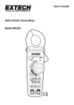
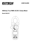
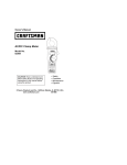
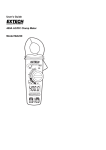
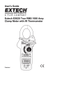
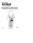
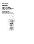
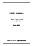
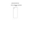
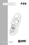
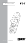
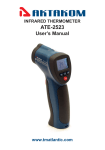
Compact AC, AC/DC
Digital Clamp Meter
User Manual
Please read this manual before switching the unit on.
Important safety information inside.
Compact AC, AC/DC Digital Clamp Meters User Manual
Contents
Page
1.Safety....................................................................................3
2.Safety Notes..........................................................................3
3.Warnings...............................................................................3
4.Cautions................................................................................3
5.Meter Description.................................................................4
6.Operation.............................................................................7
7.AC/DC Current Measurements..............................................7
8.AC/DC Voltage Measurements..............................................8
9.Resistance Measurements.....................................................8
10.Diode and Continuity Measurements..................................8
11.Capacitance Measurements................................................9
12.Frequency measurements..................................................9
13.Temperature Measurements................................................9
14.Non-Contact AC Voltage Measurements.............................10
15.Mode Button.......................................................................10
16.Data Hold Button................................................................10
17.Rel Button...........................................................................10
18.Peak Hold............................................................................11
19.Battery Replacement...........................................................11
2
Compact AC, AC/DC Digital Clamp Meters User Manual
1.Safety
International Safety Symbols
This symbol, adjacent to another symbol or terminal, indicates
the user must refer to the manual for further information.
This symbol, adjacent to a terminal, indicates that, under
normal use, hazardous voltages may be present
Double insulation
2.Safety Notes
•Do not exceed the maximum allowable input range of any function
•Do not apply voltage to meter when resistance function is selected.
•Set the function switch OFF when the meter is not in use.
3.Warnings
•Set function switch to the appropriate position before measuring.
•When measuring volts do not switch to current/resistance modes.
•When changing ranges using the selector switch always disconnect
•the test leads from the circuit under test.
•Do not exceed the maximum rated input limits.
4.Cautions
Improper use of this meter can cause damage, shock, injury or death.
Read and understand this user manual before operating the meter.
Always remove the test leads before replacing the battery.
Inspect the condition of the test leads and the meter itself for any
damage before operating the meter. Repair or replace any damage
before use.
Use great care when making measurements if the voltages are greater
than 25VAC rms or 35VDC. These voltages are considered a shock
hazard.
Remove the battery if the meter is to be stored for long periods.
Always discharge capacitors and remove power from the device under
test before performing Diode, Resistance or Continuity tests.
3
Compact AC, AC/DC Digital Clamp Meters User Manual
•Voltage checks on electrical outlets can be difficult and misleading
•because of the uncertainty of connection to the recessed electrical
•contacts. Other means should be used to ensure that the terminals
•are not "live".
•If the equipment is used in a manner not specified by the manufacturer,
•the protection provided by the equipment may be impaired.
Input Limits
Function
A
V DC, V AC
Frequency, Resistance, Diode,
Continuity, Capacitance Test
Temperature (°C/°F)
Maximum Input
400A DC/AC
600V DC/AC
250V DC/AC
250V DC/AC
5.Meter Description
1.Current clamp
2.Non-contact AC voltage indicator light
1
3.Clamp trigger
4.Rotary Function swith
5.Data Hold button
6.Back Light button
2
7.LCD display
8.MODE select button
9.PEAK button
3
10.Relative button
11.COM input jack
12.V Ω CAP TEMPHz jack
5
13.Battery Cover
400A
40A
4
°C °F
Hz
6
7
8
REL
AC/DC TRMS CLAMP METER
COM
11
4
13
V Ω Hz
Temp
CAT III
600V
9
10
12
Compact AC, AC/DC Digital Clamp Meters User Manual
1.AC DC
2.
3.
AC (alternating current) and DC (direct currrent)
Minus sign
4000 count (0 to 3999)
measurement reading with
41segments Analog Bargraph
4.AUTO
AutoRange mode
5.
Relative mode
6.
Diode test mode
7.
Audible Continuity
8.
Data Hold mode
9.°C,°F, μ,m,V,A,K,M,Ω
Units of measure list
11.Hz %
Frequency/duty cycle test mode
12.MAX MIN
MAX/MIN Hold mode
12.Pmax Pmin
Pmax Pmin Hold mode
Function
AC Current
(50/60Hz)
DC Current
DC Voltage
AC Voltage
(50/60Hz)
Resistance
Range & Resolution
40.00 AAC
400.0 AAC
40.00 ADC
400.0 ADC
400.0 mVDC
4.000 VDC
40.00 VDC
400.0 VDC
600.0 VDC
400.0 mVAC
4.000 VAC
40.00 VAC
400.0 VAC
600.0 VAC
400.0 Ω
4.000 KΩ
40.00 KΩ
400.0 KΩ
4.000 MΩ
40.00 MΩ
Accuracy (% of reading)
± (2.5 % + 8 digits)
± (2.8 % + 5 digits)
± (2.5 % + 5 digits)
± (2.8 % + 5 digits)
± (0.8% + 2 digits)
± (1.5% + 2digits)
± (2 % + 2 digits)
± (1% + 10 digits)
± (1.5% + 5 digits)
± (2.0% + 5 digits)
± (1.0% + 4 digits)
± (1.5% + 2 digits)
± (2.5% + 3 digits)
± (3.5% + 5 digits)
5
Compact AC, AC/DC Digital Clamp Meters User Manual
40.00nF
± (5.0% reading + 20 digits)
400.0nF
Capacitance 4.000μF
± (3% reading + 5 digits)
40.00μF
400.0μF
± (4.0% reading + 10 digits)
4mF
± (5.0% reading + 10 digits)
10-100kHz
Sensitivity:100V(<50Hz);
Frequency
50V(50 to 400Hz;15V
± (1.5% reading + 2 digits)
(401Hz to 100kHz)
Temp (type-K) -20 to 760°C
± (3%rdg+5°C)
(probe accuracy -4 to1400°F
± (3%rdg+9°F)
not included)
Clamp size
Diode Test
Continuity Check
Low Battery Indication
Overrange Indication
Measurements Rate
Input Impedance
Display
AC Current
AC Voltage bandwidth
Operating Temperature
Storage Temperature
Operating Humidity
Storage Humidity
Operating Altitude
Over voltage
Battery
Auto OFF
Dimensions/Weight
6
Opening 30mm (1.2") approx
Test current of 0.3mA typical; Open
circuit voltage <3V DC typical.
Threshold <50Ω; Test current <0.5mA
“ ” is displayed
“OL” is displayed
2 per second, nominal
10MΩ (VDC and VAC)
4000 counts LCD
50-60Hz (TRMS AAC)
50-60Hz ( TRMS VAC)
5 to 40°C (41 to 104°F)
-20 to 60°C (-4 to 140°F)
Max 80% up to 31°C (87°F) decreasing
linearly to 50% at 40°C(104°F)
<80%
2000meters (7000ft.) maximum.
Category III 600V
One 9V Battery
approx. 30 minutes
197x70x40mm/183g
Compact AC, AC/DC Digital Clamp Meters User Manual
Safety
For indoor use and in accordance with
Overvoltage Category II, Pollution
Degree 2. Category II includes local level,
appliance, portable equipment, etc.,
with transient overvoltages less than
Overvoltage Cat. III
6.Operation
Notices: Read and understand all warning and precaution statements
listed in the safety section of this operation manual prior to using
this meter. Set the function select switch to the OFF position when
the meter is not in use.
7.AC/DC Current Measurements
Warning: Ensure that the test leads are
disconnected from the meter before making current
clamp measurements.
1.Set the Function switch to the 400ADC/AC,40ADC/AC range.
2.Select AC or DC with the MODE button.
3.If the range of the measured is not known, select the higher range
3.first then move to the lower range if necessary.
4.Press the trigger to open
3.jaw. Fully enclose one
3.conductor to be measured.
5.In DCA mode, to ensure
3.the reading is correct,
3.please press REL button to
3.clear the reading on LCD
3.before measurement. The
3.clamp Meter LCD will
3.Display the reading.
400A
400A
40A
40A
°C °F
°C °F
Hz
NO
Hz
REL
AC/DC TRMS CLAMP METER
V Ω Hz
Temp
COM
CAT III
600V
YES
REL
AC/DC TRMS CLAMP METER
V Ω Hz
Temp
COM
CAT III
600V
7
Compact AC, AC/DC Digital Clamp Meters User Manual
8.AC/DC Voltage Measurements
1.Insert the black test lead into the negative COM terminal and the
1.red test lead into the positive V terminal.
2.Set the function switch to the V position.
3.Select AC or DC with the MODE button.
4.Connect the test leads in parallel to the circuit under test.
5.Read the voltage measurement on the LCD display.
9.Resistance Measurements
1.Insert the black test lead into the negative COM terminal and the
1.red test lead into the positive terminal.
position.
2.Set the function switch to the Ω
3.Touch the test probe tips across the circuit or component under
1.test. It is best to disconnect one side of the device under test so
1.the rest of the circuit will not interfere with the resistance reading.
4.For Resistance tests, read the resistance on the LCD display.
10.Diode and Continuity Measurements
1.Insert the black test lead banana plug into the negative COM jack
1.and the red test lead banana plug into the positive diode jack.
position.
2.Turn the rotary switch to the
3.Press the MODE button until “ “ appears in the display.
4.Touch the test probes to the diode under test. Forward voltage
1.will indicate 0.4V to 0.7V. Reverse voltage will indicate “OL”. Shorted
1.devices will indicate near 0mV and an open device will indicate “OL”
1.in both polarities.
1.For Continuity tests, if the resistance is < 50Ω, a tone will sound.
Red
Black
Forward test
8
Black
Reverse test
Compact AC, AC/DC Digital Clamp Meters User Manual
11.Capacitance Measurements
Warning: To avoid electric shock, disconnect power to the unit under
test and discharge all capacitors before taking any capacitance
measurements. Remove the batteries and unplug the line cords.
1.Set the rotary function switch to the CAP position.
2.Insert the black test lead banana plug into the negative (COM) jack.
1.Insert the red test lead banana plug into the positive (V) jack.
3.Touch the test leads to the capacitor to be tested.
4.Read the capacitance value in the display
12.Frequency measurements
1.Set the rotary function switch to the “Hz” position.
2.Insert the black lead banana plug into the negative COM jack and
1.the red test lead banana plug into the positive V jack.
3.Touch the test probe tips to the circuit under test.
4.Read the frequency on the display.
13.Temperature Measurements
Warning: To avoid electric shock, disconnect both test probes from
any source of voltage before making a temperature measurement.
1.Set the function switch to °C °F.
2.Insert the Temperature Probe into the negative (COM) and the V
1.jacks, making sure to observe the correct polarity.
3.Touch the Temperature Probe head to the part whose temperature
1.you wish to measure. Keep the probe touching the part under test
1.until the reading stabilizes (about 30 seconds).
4.Read the temperature in the display. The digital reading will indicate
1.the proper decimal point and value.
Warning: To avoid electric shock, be sure the thermocouple has
been removed before changing to another measurement function
9
Compact AC, AC/DC Digital Clamp Meters User Manual
14.Non-Contact AC Voltage Measurements
Warning: Risk of Electrocution. Before use, always test the Voltage
Detector on a known live circuit to verify proper operation.
1.Touch the probe tip to the hot conductor or insert into the hot
1.side of the electrical outlet.
2.If AC voltage is present, the detector light will illuminate.
Note: The conductors in electrical cord sets are often twisted. For
best results, rub the probe tip along a length of the cord to assure
placing the tip in close proximity to the live conductor.
Note: The detector is designed with high sensitivity. Static electricity
or other sources of energy may randomly trip the sensor. This is
normal operation.
15.Mode Button
To select DC/ACV,OHM/ Diode/Continuity/CAP,
16.Data Hold Button
To freeze the LCD meter reading, press the data hold button. The
data hold button is located on the left side of the meter (top button).
While data hold is active, the H display icon appears on the LCD.
Press the data hold button again to return to normal operation.
17.Rel Button
For DCA and Capacitance Zero & Offset adjustment.
10
Compact AC, AC/DC Digital Clamp Meters User Manual
18.Peak Hold
The Peak Hold function captures the peak AC voltage or current.
The meter can capture negative or positive peaks as fast as 1
millisecond in duration.
1.Turn the function switch to the A or V position.
2.Use the MODE button to select AC .
3.Allow time for the display to stabilize.
4.Press and Hold the PEAK button until “CAL” appears in the display.
1.This procedure will zero the range selected.
5.Press the PEAK button, Pmax will display.
6.The display will update each time a higher positive peak occurs.
7.Press the PEAK button again, Pmin will display. The display will now
1.update and indicate the lowest negative peak.
8.To return to normal operation, press and hold the PEAK button
1.until the Pmin or Pmax indicator switches off.
Note: If the Function switch position is changed after a calibration
the Peak Hold calibration must be repeated for the new function
selected.
19.Battery Replacement
1.Remove the one rear Phillips head screw
2.Open the battery compartment
3.Replace the Requires One 9V battery
4.Re-assemble the meter
11
Rev.090801
Compact AC, AC/DC Digital Clamp Meters User Manual