1
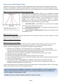
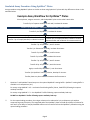
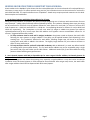
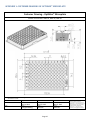
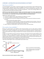
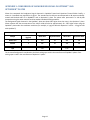
Instruction Manual OptiMax™ Microplate For Use with Automated Liquid Handling Systems Catalogue Numbers: OMP-2, OMP-10, OMP-50 Manufactured by: Siloam Biosciences, Inc. 413 Northland Blvd. Cincinnati, Ohio 45240 FOR RESEARCH USE ONLY Not for use in clinical diagnostic procedures. Read the Instruction Manual in its entirety before using the OptiMax™ microplate. Please refer to the Assay Transfer Guide for detailed assay development procedures. The assay transfer guide refers to the Optimiser™ (manual use) plate model – OptiMax™ plate may be substituted with differences as noted in this Manual. OptiMax™ microplates are warranted to perform in conformance with published product specifications in effect at the time of sale as set forth in product documentation and/or package inserts. Products are supplied for Research Use Only. The use of this product for any clinical diagnostic applications is expressly prohibited. The warranty provided herein is valid only when used by properly trained individuals and is limited to six months from the date of shipment and does not extend to anyone other than the original purchaser. No other warranties express or implied, are granted, including without limitation, implied warranties of merchantability, fitness for any particular purpose, or non-infringement. Buyers’ exclusive remedy for non-conforming product during the warranty period is limited to replacement of or refund for the non-conforming product. Table of Contents INTRODUCTION ....................................................................................................................................................................... 2 Automatic Pipetting System Setup ......................................................................................................................................... 3 System Requirements: ........................................................................................................................................................ 3 Reagent and Sample Preparation: ...................................................................................................................................... 3 Position of Tips While Dispensing: ...................................................................................................................................... 3 Liquid Class Configurations: ................................................................................................................................................ 4 Fluorescence Plate Reader Setup ........................................................................................................................................... 5 Sandwich Assay Procedure Using OptiMax™ Plates ............................................................................................................... 6 KEEPING INCUBATION TIMES CONSISTENT FOR EACH WELL: ................................................................................................ 7 TROUBLESHOOTING: ............................................................................................................................................................... 8 APPENDIX 1: CUSTOMER DRAWING OF OPTIMAX™ MICROPLATE ...................................................................................... 10 APPENDIX 2: ALTERNATIVE ASSAY PROCEDURES ON OPTIMAX™ ........................................................................................ 11 Rapid Assay on OptiMax™: ............................................................................................................................................... 11 Ultra-sensitive Assay on OptiMax™: ................................................................................................................................. 11 APPENDIX 3: COMPARISON OF BACKGROUND SIGNAL IN OPTIMAX™ AND OPTIMISER™ PLATES ..................................... 12 APPENDIX 4: DETAILED PROCEDURE FOR READER GAIN SETTING VERIFICATION ............................................................... 13 The user manual for OptiMax™ microplates also includes references to Optimiser™ microplate. Note that Optimiser™ microplate is designed for manual use and detailed Assay Transfer Methods have been developed using the Optimiser™ microplate. These methods are also applicable to the OptiMax™ microplate with changes as noted in this User Manual. Page 1 INTRODUCTION Siloam Biosciences’ Optimiser™ technology platform offers a rapid and sensitive chemifluorescent-based ELISA procedure that uses very small sample volumes. The speed, sensitivity, and small sample requirements are enabled by the unique microfluidic design of the Optimiser™ & OptiMax™ microplates. Standard immunoassay reactions such as analyte capture and detection occur within a ~ 5 µL microfluidic reaction chamber. The unique microchannel geometry and small reaction volumes favor rapid reaction kinetics. Typical Optimiser™ assay procedures utilize 5 µL sample volumes and each reaction step is completed within 10 - 20 minutes. Most standard Optimiser™ technology-based ELISAs are completed within approximately 2 hours. Please refer to the Optimiser™ Technology page on Siloam’s website (www.siloambio.com) for more details regarding the principles behind the Optimiser™ & OptiMax™ microplate platform. Figure 1.Optimiser™ microplate: The Optimiser™ microplate is a revolutionary new microplate format. With an ANSI/SBS compliant 96-well layout, the Optimiser™ integrates the Power of Microfluidics to allow for low volume, rapid, and sensitive immunoassay protocols. Figure 1 shows the Optimiser™ microplate schematic with a magnified view of one “cell” of the Optimiser™. Each cell of the Optimiser™ has a loading well (only used to add reagents) and a microfluidic reaction chamber. Reagents/samples are added to the well and transported via capillary action to an absorbent pad (not shown). The unique design of the Optimiser™ allows the well to be drained but each liquid is trapped in the channel by capillary forces. As the next liquid volume is added, the capillary barrier is broken and the liquid within the microchannel is drawn out by the absorbent pad and replaced by the new reagent. All assay reactions occur within the microfluidic reaction chamber. The automation compatible OptiMax™ microplate is built on the same principles as the Optimiser™ microplate. The OptiMax™ plate integrates the holder and absorbance pads within the plate body. The resulting footprint is identical to the standard ANSI/SBS 96-well layout and fits on the corresponding hardware of all robotic liquid handling systems. The built-in pads provide adequate absorbent capacity for all anticipated ELISA procedures and do not need to be removed prior to plate reading. The opaque sealing layer of the OptiMax™ plate prevents excitation of liquids absorbed within the pad and allows the plate to be read without disassembly. Microfluidic Microplate Absorbent Pads Holder Figure 2.Assembled OptiMax™ plate (left) and illustration of plate components (right). NOTE: Optimiser™ and OptiMax™ are virtually identical in performance. Optimiser™ microplates are limited to manual use (external holder must be manually detached prior to reading). OptiMax™ plates are full-automation compatible with no need for disassembly. Page 2 Automatic Pipetting System Setup System Requirements: The system must be capable of precisely dispensing 5μL and 30 µL volumes. The system must have carrier(s) capable of holding SBS standard 96 well plates. The system should be equipped with 8 (or 12) channel pipettor and/or 96-channel pipettor head OptiMax™ plate is compatible with both disposable and fixed tips. Do not use low retention tips Minimize dust in the working environment. Reagent and Sample Preparation: Solutions must be free of visible insoluble material (e.g. particulates, precipitate). Centrifuge for 10 minutes at 13,000 g is necessary during sample preparation Position of Tips While Dispensing: While dispensing the liquid into the OptiMax™ plate, the pipettor tips must contact the well surface. Solutions must be dispensed onto the surface of the conical well (shown as the red area in figure below): Well surface Through hole Once the liquid touches the well surface, it will flow into the microchannel beneath the loading well via the through hole. The basic structure of an OptiMax™ well is shown below. Please see Appendix 1 at Page X for detailed plate drawing. Top o 45 2.65 mm Bottom Siloam recommends positioning pipettor tips relative to the loading well as illustrated below: With the programmed setting illustrated on right, the tip will bend a little as it comes in contact with the well surface. The resulting tip-to-well contact will ensure proper delivery of solutions. This setting has been used successfully with various automatic systems. Please see complete list on page 3. Actual position IMPORTANT: DO NOT POSITION THE TIP INSIDE THE THROUGH HOLE TIP MUST CONTACT WELL SURFACE DURING DISPENSE Programmed setting 1 mm 2.1 mm Page 3 Liquid Class Configurations: The following recommendations for precisely dispensing small volume of solution into the OptiMax™ plate can ensure correct dispense operation without introducing bubbles. 1) Dispensing rate: Use low dispense rate (20-50 µl/sec) to dispense small volume of liquid into OptiMax™ plate. 2) Do not “blow out” the liquid in dispensing step. 3) Aspirate extra liquid: Aspirate the volume that you intend to dispense (e.g. 5 μL) plus an additional 2-5 µL of extra solution to avoid inadvertently dispensing air into the well and creating a bubble. 4) For aspiration: Small quantities of assay reagents will be used in most of steps. Siloam suggests using reservoirs with v-shaped bottoms for most reagents and always aspirating from near the bottom of the v-shaped reservoir. 5) Dispensing sample volume less than 5 µL: Sample volumes can be reduced to as low as 2 μL for OptiMax™based assay procedures without compromising assay sensitivity. Please consult with Siloam technical support for appropriate settings for precisely dispensing less than 5 µL solutions onto the OptiMax™ well surfaces. Siloam has tested OptiMax™ plates on the following automation platforms. Siloam can provide more detailed settings and programs for the systems listed below. Please contact Siloam technical support for more information. Table 1. Automation systems verified with OptiMax™ Plates Manufacturer BioTek Tecan Hamilton Beckman Coulter Model Precision EVO100 MicroLab Star BioMek FXP System configuration 8 channel pipettor 8 channel pipettor, RoMa Arm, and M200 reader 12 channel pipettor and 96-channel head 8 channel pipettor and 96-channel head Page 4 Tip Disposable tip Disposable & Fixed Disposable Disposable Fluorescence Plate Reader Setup OptiMax™-based assays are compatible with standard fluorescence plate readers and multi-mode plate readers with fluorescence read capability. Below is the general guidance for setting up the readers. The “Technical Support” section on Siloam’s website offers detailed guidance on the set up of several major brands of instruments as illustrative examples. Step 1: Selecting the wavelength for excitation and emission light: 570 585 Figure 3.Normalized absorption (left) and emission (right) spectra of OptiGlow™chemifluorescent substrate. Assays performed on the OptiMax™ platform use the OptiGlow™ substrate system which can be detected using the appropriate excitation and emission settings (Figure 3). Quantitation does not require filters that precisely match the excitation/emission maxima. However, a non-overlapping filter set with a bandpass that includes the excitation/emission spectra is required. Wavelengths can be set at 530-575 nm for excitation and at 585-630 nm for emission. Below are examples for different types of readers: Filter-based readers: Install 528/20 nm (or similar) filter for excitation and 590/35 nm (or similar) filter for emission. Monochromator-based readers: Set excitation wavelength at 544 nm and emission wavelength at 590 nm. Readers with pre-configured optical set: Select the wavelength setting for Rhodamine or Cy3. Step 2: Selecting the plate type: The OptiMax™ microplate fits the 96-well SBS standard in all specifications. Please use “96-well standard” or similar selection when setting the plate type. Step 3: Selecting the probe direction: Use “top reading” for probe direction. Step 4: Selecting the sensitivity/gain: When defining reading parameters for fluorescence analysis, setting the PMT sensitivity (or “gain” in some types of fluorescence readers) is important for obtaining useful measurements. A manual sensitivity/gain setting is recommended for reading OptiMax™ microplates. The procedure is described below: 1) Dispense 50 µL of OptiGlow™-A, 50 µL of OptiGlow™-B, 1 µL of OptiGlow™-C, and 1µL of horseradish peroxidase-labeled streptavidin (SAv-HRP) stock solution (Siloam Biosciences) in a clean plastic tube, mix well, and wait for 2 minutes. The substrate will be fully developed and stable for hours. 2) Load 4 µL of the mixture into well A1 of an OptiMax™ microplate and wait until the well is empty. 3) Read well A1 using a range of gain settings. 4) Select the gain setting which gives an RFU reading for well A1 closest to 11,000. 5) Using the same gain setting, read one blank well of the OptiMax™ plate.The RFU reading should be less than 50. 6) Save or record this gain setting. 7) This defines the maximum reading (RFUmax) that OptiMax™-based assays can reach with this reader gain/sensitivity setting and the 50:50:1 substrate mix ratio. Note that the RFU readings will be higher than 11,000 RFU if different substrate mix ratios are used. The gain setting will be valid for all OptiMax™-based assays. Repeat Step 4 if a) using a different reader, or b) if changing elements of the reader’s optical unit such as light bulb or filters. NOTE: The signal intensity from OptiMax™ and Optimiser™ plates will be different. In order to compare results between the two platforms, the instrument gain needs to be adjusted independently as described below for both the OptiMax™ and the Optimiser™ plates. APPENDIX 4 describes a detailed method to troubleshoot reader gain settings. Page 5 Sandwich Assay Procedure Using OptiMax™ Plates Assay procedures using OptiMax™ plates are similar to those using Optimiser™ plates with key differences shown in the workflow below: Example Assay Workflow for OptiMax™ Plates Place tip boxes, reagent reservoirs, and the OptiMax™ plate on the robot’s work table Transfer 5 µL of capture antibody to each well, incubate 10 minutes Transfer 5 µL of OptiBlock™ OR Protein free Block buffer, wait 5 minutes* Transfer 5 µL of OptiBlock™, incubate 10 minutes Standard Procedure (Single 5 μL dispense) Transfer 5 µL of sample/standard, incubate 10 minutes Repeat Load Procedure** (Multiple 5 μL dispenses) Transfer 5µL of sample/standard, incubate 5 minutes. Repeat transfer and incubation to increase sensitivity. Transfer 5 µL of OptiWash™, wait 5 minutes. Transfer 5 µL of detection antibody, incubate 10 minutes. Transfer 5 µL of OptiWash™, wait5 minutes. Transfer 5 µL of SAv-HRP, incubate 10 minutes. Transfer 5 µL of OptiWash™, wait 5 minutes. Transfer 30 µL of OptiWash™, wait 10 minutes. Again, transfer 30 µL OptiWash™, wait 10 minutes Transfer 5µL OptiGlow™ working solution, develop 15 minutes. Transfer plate to a plate reader and measure the fluorescence. * Optimiser™ and OptiMax™ based assays use the optimal OptiBind™ coating buffer. OptiBind™ coating buffer is available in 12 compositions (A-L). For assays using OptiBind™ A-E – use Protein free blocking buffer (Pierce, Cat#37572) following the capture antibody load step For assays using OptiBind™ F-L – Use OptiBlock™ buffer following capture antibody load step DO NOT use OptiWash™ buffer following capture antibody load step ** For the repeat loading procedure, the antigen volume can be reduced to 2 µL per dispense cycle without compromising assay sensitivity. The integrated pad of the OptiMax™ plate can hold up to 300 µL of solution for each well. Up to 200 µL of sample/standard solution can be transferred into the OptiMax™ plate when using the repeat loading procedure. Page 6 KEEPING INCUBATION TIMES CONSISTENT FOR EACH WELL: Kinetic studies on the OptiMax™ plate shows that the reaction/adsorption in the microchannel will reach equilibrium in 10 minutes in most assays. To achieve optimal assay precision, the incubation times must be consistent for each well in each REACTION STEP. The rapid incubation times of OptiMax™- based assays require particular attention to this detail. Some examples are listed below: 1. Use 8-channel pipettor with 200 µL disposable tips for all steps. During the assay procedure, the pipettor will perform multiple dispensing over 12 columns with same solution for most steps (example – adding capture antibody solution followed by buffer). For incubation following these steps, the timing will be consistent for each well since the pipettor follows the same pattern for each load (i.e. Column 1 will have first load of capture at t = 00:00 min and buffer at t = 10:00 min. Corresponding duration for Column 12 may be 00:20 and 10:20 min respectively). The 2 exceptions to this will occur when (a) antigen is added since pipettor tips needs to replaced/washed and (b) 30 µl wash steps after HRP addition since pipettor cannot accommodate volume for 12 columns. Suggested workarounds include: To keep consistent time for each well in antigen incubation: the pipettor needs to dispense the wash buffer following the same pattern as antigen addition. Time delay may be applied between each dispensing in this washing step. The “incubation” duration for wash buffer, following antigen step, will be set at 10 minutes starting after wash buffer is added in last column. The slightly longer duration for prior columns will have no effect on assay performance. To keep consistent time for each well in SAv-HRP incubation: add an additional 5 µL wash step before load 30 µL washing buffer (see workflow above). The 5 µl wash buffer addition step can be completed using a single pass with a 200 µl tip and flushes out the HRP solution. Additional washes (30 µl) can follow different timing patterns without affecting assay performance. 2. Use 8-channel pipettor with 200 µL disposable tips for most reagent & buffer addition, 96-channel pipettor for antigen addition. Using 96-channel pipettor can reduce the pipetting time, especially in sample addition. It may also lead to inconsistent incubation times if 8-channel pipettor is used to dispense the wash buffer after antigen step. Hence, the wash buffer after antigen addition should also be dispensed with 96-channel pipettor. Page 7 TROUBLESHOOTING: The OptiMax™ microplate and ELISA kits have been designed and manufactured to ensure problem-free sample analysis. However, Siloam Biosciences has prepared the following guidance for trouble shooting problems that might be encountered due to the unique features of the Optimiser™ technology as well as problems that can be encountered with immunoassays in general. Problem Possible Cause Solution A bubble is in the well. Follow recommended liquid class configurations. Liquid does not drain from the OptiMax™ well or does not drain within 10 minutes. No signal or unexpectedly low signal Unexpectedly high signal Poor precision Signal of lower standard(s) are < 0 following background subtraction. Sample contains particulates. Centrifuge sample for 10 min at 13,000 RPM, or Filter the sample using a 0.2 µm filter. OptiBind™ A-E coating buffer step followed by (a) OptiBlock™ or (b) OptiWash™ Use Protein free blocking buffer (Pierce, Cat#37572) following the capture antibody load step for assays using OptiBind™ A-E. Standard has degraded. Use standard on the day of its reconstitution Incorrect reader filters Confirm filters meet requirements for substrate. Use within specified expiration period. Store according to recommended storage temperature. Thaw OptiGlow™ - C thoroughly before preparing substrate working solution. Prepare substrate no more than 30 minutes before plate is read. Confirm filters meet requirements for substrate. Antibodies or SAv-HRP are degraded. Substrate was prepared incorrectly. Substrate working solution has degraded. Incorrect reader filters with overlapped wavelength bandwidth Dust in the well Minimize the dust in working environment Reagent contamination Avoid cross contamination in reagents. Always change the tips when handling different buffers/reagents. Program to keep consistent incubation time for each well. Please check the precision of the pipettor. Inconsistent incubation time between wells Poor dispensing precision of the pipettor Degraded standard Degraded capture antibody Page 8 Use standard on the day of its reconstitution, or Thaw single use aliquots fresh on each test day. Avoid repeated freeze-thaws. Use within specified expiration period. Store according to recommended storage temperature. Technical Assistance: If you require assistance, please contact Siloam Biosciences, Inc. Technical Support at 513-429-2976 or [email protected]. Additional technical assistance is available under the Technical Support tab on the Siloam Biosciences web site (http://siloambio.com/). Using Optimiser™ Immunoassay Microplate Video Optimiser™ User’s Guide Reader Settings Quick Reference Guide Frequently Asked Questions Application Notes Two additional videos appear under the Technology tab of the web site. Optimiser™ Principles of Operation Running an Assay with Optimiser™ Better Immunoassays Through Innovative Microfluidics DOC ID: OPTI-2-MS-0072-A1 Page 9 Siloam Biosciences, Inc. 413 Northland Blvd., Cincinnati, OH 45240 USA Phone: +1 (513)-429-2976 Fax: +1 (513)-429-2946 http://www.siloambio.com APPENDIX 1: CUSTOMER DRAWING OF OPTIMAX™ MICROPLATE Customer Drawing – OptiMax™ Microplate Valid for Item Number: OMP-02, OMP-10, OMP-50 - Customer drawing subject to change without notice. - All dimensions in mm. Prior Issue Prepared Approved Released Revision Date Date Date April 4, 2012 April 5, 2012 May 2, 2012 Name Name Name George Kauffung Sean Lee Sean Lee Date Page 10 CONFIDENTIAL: Information contained in this document or drawing is confidential and proprietary to Siloam Biosciences, Inc. This document may not be reproduced for any reason without written permission from Siloam Biosciences, Inc. All rights of design, invention, and copyright are reserved. APPENDIX 2: ALTERNATIVE ASSAY PROCEDURES ON OPTIMAX™ Rapid Assay on OptiMax™: The standard OptiMax™ assay procedure, as described on page 6 of this Instruction Manual, requires approximately 100 minutes to complete. Adsorption kinetics study on the OptiMax™ shows that; for most assay steps, in ~ 5 minutes, ~ 92% of peak adsorption (or binding) is completed. More importantly, from 5 – 30 min the adsorption only changes from ~ 92% to ~ 96%. This offers the potential to reduce to the assay time significantly. In some cases, reducing incubation times may reduce assay sensitivity and/or assay precision slightly. CAUTION: Users should empirically determine through a structured DOE approach if the changes suggested below have a noticeable effect on assay performance. The following suggestions should be used as a guide and should be verified for each assay. PLEASE CONSULT SILOAM TECHNICAL SUPPORT FOR FURTHER ASSISTANCE. Suggestions for reducing assay duration: 1) In most cases, incubation time for capture antibody can be reduced to 5 minutes. 2) In most case, incubation time for blocking can be reduced to 5 minutes. 3) If the expected molar concentration of antigen will not be higher than 10% of detection antibody concentration, users may: Skip the wash step after antigen incubation. Mix the detection antibody with antigen, and then transfer to OptiMax™ plate for incubation. Please note that antibody concentration optimization procedure described in the Assay transfer guide may need to be repeated if the antigen-detection antibody mixture method is used. 4) Capture antibody pre-coated OptiMax™ plate can be used to shorten the assay procedure. Ultra-sensitive Assay on OptiMax™: Because of the unique features of the OptiMax™ plate and ELISA procedures, users can apply sample to individual microfluidic reaction chambers multiple times. The result is a significant improvement in assay sensitivity when ultralow detection limit is required. The additional sample applications can be performed manually for a limited number of repeat sample loads but Siloam strongly recommends use of a laboratory sample processor for the ultra-high sensitive protocol. The data in the figure below illustrates the sensitivity and dynamic range obtained using the standard OptiMax™ ELISA procedure (a single 5 µL sample addition) and the improvement in sensitivity that is gained by performing 20 consecutive 5 µL sample applications to individual reaction chambers using a laboratory sample processor. Each additional sample incubation is 5 minutes in length. Thus with 95 additional minutes of assay time, the total assay time is approximately 3 hours with a corresponding increase in assay sensitivity of 20-fold. The repeat sample loading methods is a reliable and simple method to “tune” the sensitivity of the assay to the desired range simply by adjusting the number of sample addition (and incubation steps). 100000 5 µL sample 5 µL sample, repeatedly load 20 times RFU 10000 1000 100 0.1 1 10 100 1000 Human IL-6 (picogram/mL) Please contact Siloam’s technical support for additional details. Page 11 Figure 4. Ultra-sensitive assay using repeat sample loading technique with the OptiMax™ Human IL-6 ELISA kit with an automated pipetting station. APPENDIX 3: COMPARISON OF BACKGROUND SIGNAL IN OPTIMAX™ AND OPTIMISER™ PLATES Siloam has compared the background signal observed in OptiMax™-based and Optimiser™-based ELISAs. Briefly, a mouse IL-2 standard was prepared at 3 pg/mL. The standard and its diluent were dispensed to 48 capture antibodycoated and blocked wells of an OptiMax™ and an Optimiser™ plate. The plates were processed in a side-by-side comparison using the same materials and the standard sandwich ELISA procedure. The background signal observed in the OptiMax™ plate was about 30% higher than that seen in the Optimiser™ plate. Siloam expects that the concentration of the LOD or LOQ will also be approximately 30 – 50% higher when using the OptiMax™ plate under the conditions used here (for example, a 3 pg/mL LOD with Optimiser™ and 4 – 4.5 pg/mL LOD with OptiMax™). OptiMax™ Optimiser™ Sample Concentration (pg/mL) Mean RFU Replicate Wells Mean RFU Replicate Wells Mouse IL-2 3 494 48 482 48 Diluent 0 336 48 259 48 S/N 1.47 1.87 The increased background is attributed to the black sealing tape used in the manufacture of OptiMax™ plates. Clear sealing tape is used in the manufacture of Optimiser™ plates. Page 12 APPENDIX 4: DETAILED PROCEDURE FOR READER GAIN SETTING VERIFICATION Most fluorescence/ multi-mode readers tested with Optimiser™ and OptiMax™ plates show excellent performance and ability to set reader gain as described in the Reader Setup section. If users believe that the reader does not offer satisfactory sensitivity and/or dynamic range; the following procedure can be used for additional verification. A list of readers tested with Optimiser™ plates is available on Siloam’s website under the Technical Support Tab. Chemifluorescence Solution Preparation (NOTE MIX RATIO): 1) In well A1 of a clean 96-well v-bottom plate, add 50 µL of OptiGlow™-A, 50 µL of OptiGlow™-B, 5 µL of OptiGlow™-C, and 1 µL of supplied SAv-HRP stock solution, mix well, and wait for 2 minutes. The substrate will be fully developed to a red fluorescence dye solution, and stable for hours. 2) Prepare 1:2 serial diluted solutions with DI water to prepare 15 fluorescence solutions with 1 zero: a) Load 50 µL of DI water to well B1-H1, and A2-H2 b) Transfer 50 µL of solution from well A1 to well B1 and mix well. c) Change the tip, repeat same procedure till well H1, then continue to well B2 and repeat till well G2, leaving well H2 as zero. A B C D E F G H 1 no dilution 1/2 1/4 1/8 1/16 1/32 1/64 1/128 2 1/256 1/512 1/1024 1/2048 1/4096 1/8192 1/16384 0 Transfer to OptiMax™ and reading: Transfer 4 µL solution of each solution to corresponding well on OptiMax™ plate. Wait for all the wells to empty. Read with different gain settings. For capability to run wide dynamic range assay (729 folds) in OptiMax™, the reader should have: o Clear discrimination in fluorescence signal intensity from wells A1-D2 AND o Clearly distinguish well D2 to well H2. For capability to run standard dynamic range assay (64 folds) in OptiMax™, the reader should have: o Clear discrimination in fluorescence signal intensity from wells C1-D2 o Clearly distinguish well D2 to well H2. The following results show typical data on a BioTek Flx800 Fluorescence reader: A1 B1 C1 D1 E1 F1 G1 H1 22794 17528 10957 6126 3503 1747 907 461 A2 B2 C2 D2 E2 F2 G2 H2 278 159 93 54 34 23 16 10 Page 13