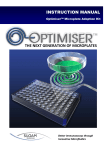
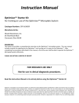
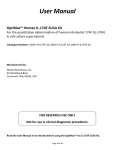
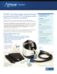
1
TECHNICAL NOTE TN0002: Optimiser™ Microplate System (ELISA) Setup Guide ® on the BioTek FLx800™ Fluorescence Microplate Reader THE NEXT GENERATION OF MICROPLATES Better Immunoassays through Innovative Microfluidics TableofContents READER SETUP WITH BIOTEK® FlX800™ READER: .................................................................................................................. 3 Recommended Optics ......................................................................................................................................................... 3 Instrument Setup ................................................................................................................................................................ 3 Sensitivity Adjustment ........................................................................................................................................................ 9 GENERAL READER SETUP GUIDANCE: ................................................................................................................................... 12 SILOAM BIOSCIENCES, INC. (www.siloambio.com) Page 2 of 13 DOC ID: OPTI‐2‐MS‐0006‐A1 READERSETUPWITHBIOTEK®FlX800™READER: The BioTek® FLx800™ Fluorescence Microplate Reader has been tested for compatibility with Siloam's Optimiser™ microplate System in ELISA assay with OptiGlow™ chemifluorescent substrate. Please refer to the Optimiser™ Technology page on Siloam’s website for more details on the principles behind the Optimiser™ microplate platform. For more detailed information and technical support of BioTek® instruments or Gen5 software, please contact BioTek® Instruments at 1‐888‐451‐5171. RecommendedOptics BioTek® Instruments Part Number Wavelength Excitation 7082247 528/20 nm (or similar) Emission 7082224 590/35 nm (or similar) InstrumentSetup 1) Turn on the plate reader, and open up BioTek® Gen5 software on computer. 2) Select “Protocol” in the "Create a New Item" menu. SILOAM BIOSCIENCES, INC. (www.siloambio.com) Page 3 of 13 DOC ID: OPTI‐2‐MS‐0006‐A1 3) A blank protocol will open. Select "Procedure" on the left hand side and a new window will open up. Select “96 WELL PLATE” in the plate type. Optimiser™ plate fits 96‐well SBS standard in all specifications. Please use the similar 96‐well plate type option in other fluorescence readers, such as “96‐well plate”, “96‐well standard” or “96‐well SBS standard”. SILOAM BIOSCIENCES, INC. (www.siloambio.com) Page 4 of 13 DOC ID: OPTI‐2‐MS‐0006‐A1 4) Select the "Read" tab. Select "Fluorescence" and "Endpoint" from the drop‐down menus. Select the proper filters, “Top” for optic position and input “45” for sensitivity*, as shown below. Also, select the wells of your plate you wish to read by clicking on the "Full Plate" icon to the left. * Please see Sensitivity Adjustment at Page 9 SILOAM BIOSCIENCES, INC. (www.siloambio.com) Page 5 of 13 DOC ID: OPTI‐2‐MS‐0006‐A1 5) Your screen should now look like the picture below, and then select "OK". In the upper left, under "File", save your protocol. SILOAM BIOSCIENCES, INC. (www.siloambio.com) Page 6 of 13 DOC ID: OPTI‐2‐MS‐0006‐A1 6) To run an actual experiment, click on "File" again, and select "New Experiment" from the drop‐down list. A smaller window will appear; select your protocol and click "OK". SILOAM BIOSCIENCES, INC. (www.siloambio.com) Page 7 of 13 DOC ID: OPTI‐2‐MS‐0006‐A1 7) A new window will again appear; this is the experiment window. Insert your plate to be read and click on the "Read Plate" icon with the small green arrow (second from last icon in the lower toolbar). SILOAM BIOSCIENCES, INC. (www.siloambio.com) Page 8 of 13 DOC ID: OPTI‐2‐MS‐0006‐A1 8) One last popup will appear. Select "Read" and instrument will commence reading your plate. Note: There are several options for collecting data from the BioTek® Gen5 software. Data can be exported directly to excel, or appropriate macros can be prepared within the BioTek® software. For more information on data output options, please refer to reader user manual or contact BioTek® Technical Support. SensitivityAdjustment When defining reading parameters for Fluorescence analysis, setting the PMT sensitivity (or “gain” in some types of fluorescence reader) is important for obtaining useful measurements. BioTek® recommends a setting between 40 ‐120 for Fluorescence assays. Siloam’s OptiGlow™ is a strong chemifluorescence substrate which requires low value on sensitivity setting. A manual sensitivity/gain setting is recommended for reading Optimiser™ microplates. Following is an instruction for determining the sensitivity setting with mixture of HRP and OptiGlow™ substrate. It use BioTek® Flx800 as an example but can be applied to other fluorescence microplate reader as well. Material: 1) Siloam’s SAv‐HRP (cat# OMR‐HRP). Note: Any HRP conjugate with concentration greater than 1 µg/mL can be used for this test with following experimental protocol 2) Siloam’s OptiGlow™ substrate. 3) One Optimiser™ Microplate. Well A1 will be used for the sensitivity adjustment SILOAM BIOSCIENCES, INC. (www.siloambio.com) Page 9 of 13 DOC ID: OPTI‐2‐MS‐0006‐A1 Experimental Procedure: 1) In a clean plastic tube, add 50 µL of OptiGlow™‐A, 50 µL of OptiGlow™‐B, 1 µL of OptiGlow™‐C, and 1 µL of supplied SAv‐HRP stock solution, mix well, and wait for 2 minutes. The substrate will be fully developed and stable for hours. 2) Load 4 µL of mixture into well A1 of Optimiser™ microplate and wait until the well is empty (do not use pad/holder) 3) There are two methods to determine the sensitivity with BioTek® Flx800: a) Try different sensitivity manually so that the signal from well A1 is close to 11,0001. b) Use auto sensitivity adjustment. An example operation for BioTek® Flx800 is shown as below: Follow the instruction of Instrument Setup at Page 3, in step 4), select the “option” tab under the sensitivity instead of setting the sensitivity manually. Your screen should now look like the picture below. Select "Automatic Sensitivity Adjustment" and "Scale to High Wells". Also, select A1 as the reference well by clicking on the tab next to “Scale Wells”. Input “11000”. The reader will automatic choose the gain/sensitivity which makes the reading of A1 close to the given value. 1 The RFUmax value of 11,000 is selected for readers with linear operating range up to ~100,000 RFU. Setting RFUmax=11,000 will allow users to: (a) compare results with Siloam’s data and allow for effective troubleshooting if needed and (b) use the wide dynamic range protocols as described in Application Note: “AN0015 ‐ Optimiser™ Assays with Extended Dynamic Range” SILOAM BIOSCIENCES, INC. (www.siloambio.com) Page 10 of 13 DOC ID: OPTI‐2‐MS‐0006‐A1 And then find the sensitivity value by right clicking the “Procedure” and selecting “AutoSensitivity Results”, and use the number for setting the sensitivity. 4) Use the same sensitivity setting, read one blank well of Optimiser™, the readout should be less than 50. 5) Save or record this sensitivity setting. 6) This defines the max reading (RFUmax) that Optimiser™ based assays can reach with this reader sensitivity setting. The gain setting will be valid for all Optimiser™ based assays. Readjust sensitivity only if a) changing the reader or b) changing the optical unit such as light bulb, filters, etc. SILOAM BIOSCIENCES, INC. (www.siloambio.com) Page 11 of 13 DOC ID: OPTI‐2‐MS‐0006‐A1 GENERALREADERSETUPGUIDANCE: Optimiser™ based assays are compatible with standard fluorescence plate readers and multi‐mode plate readers with fluorescence reading capability. Below is the general guidance for setting up the readers. For further assistance, please contact Siloam’s technical support. Step 1: Selecting the wavelength for excitation and emission light: Figure 5. Normalized absorption (left) and emission (right) spectra of OptiGlow™ chemifluorescent substrate. Assays on Optimiser™ uses OptiGlow™ substrate, which can be detected using the appropriate excitation and emission settings (Figure 5). Quantitation does not require filters that precisely match the excitation/emission maxima. However, a non‐overlapping filter set with a bandpass that includes the excitation/emission spectra is required. Wavelengths at 530‐575 nm for excitation and 585‐630 nm for emission can be used for detection. Below are examples for different types of readers: Filter‐based readers: install 528/20 nm (or similar) filter for excitation, and 590/35 nm (or similar) filter for emission Monochromator‐based readers: in wavelength setting, set excitation at 528/20 nm, and emission at 590/35 nm Readers with pre‐configured optical set: select the wavelength setting for Rhodamine or Cy3. Step 2: Selecting the plate type: Optimiser™ microplate fits 96‐well SBS standard in all specifications. Please use “96‐well standard” or similar in plate type setting. Step 3: Selecting the probe direction: Please use “top reading” for probe direction. Step 4: Selecting the sensitivity/gain: When defining reading parameters for fluorescence analysis, setting the PMT sensitivity (or “gain” in some types of fluorescence reader) is important for obtaining useful measurements. A manual sensitivity/gain setting is recommended for reading Optimiser™ microplates. The procedure is as described below: 1) In a clean plastic tube, add 50 µL of OptiGlow™ A, 50 µL of OptiGlow™ B, 1 µL of OptiGlow™ C, and 1 µL of Siloam’s SAv‐HRP stock solution, mix well, and wait for 2 minutes. The substrate will be fully developed and stable for hours. Note: Any HRP conjugate with concentration greater than 1 µg/mL can be used for this test with following experimental protocol 2) Load 4 µL of mixture into one well of Optimiser™ microplate and wait until the well is empty (do not use pad/holder) 3) Read that well in reader with various gain setting. 4) Select the gain which gives the RFU reading closest to 11,000. 5) Use the same gain setting, read one blank well of Optimiser™, the readout should be less than 50. 6) Save or record this gain setting. 7) This defines the max reading (RFUmax) that Optimiser™ based assays can reach with this reader gain/sensitivity setting. The gain setting will be valid for all Optimiser™ based assays. Repeat Step 4 if a) changing the reader or b) changing the optical unit such as light bulb, filters, etc. SILOAM BIOSCIENCES, INC. (www.siloambio.com) Page 12 of 13 DOC ID: OPTI‐2‐MS‐0006‐A1 Technical Assistance: If you require assistance, please contact Siloam Biosciences, Inc. Technical Support at 513‐429‐2976 or [email protected]. Additional technical assistance is available under the Technical Support tab on the Siloam Biosciences web site (http://siloambio.com/). Using Optimiser™ Immunoassay Microplate Video Optimiser™ User’s Guide Reader Settings Quick Reference Guide Frequently Asked Questions Application Notes Two additional videos appear under the Technology tab of the web site. Optimiser™ Principles of Operation Running an Assay with Optimiser™ Siloam Biosciences, Inc. 413 Northland Blvd., Cincinnati, OH 45240 Phone: 513‐429‐2976 Fax: 513‐429‐2946 www.siloambio.com Better Immunoassays Through Innovative Microfluidics SILOAM BIOSCIENCES, INC. (www.siloambio.com) Page 13 of 13 DOC ID: OPTI‐2‐MS‐0006‐A1