1
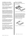
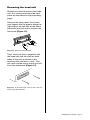
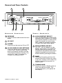
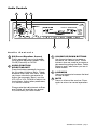
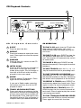
®
L
A
B
O
R
A
T
O
R
I
E
USER’S MANUAL
S
page
SCD300
In-Dash CD Receiver
Congratulations on your
purchase of a Sound Storm
Laboratories Receiver.
It has been designed, engineered
and manufactured to bring you the
highest level of performance and
quality, and will afford you years of
listening pleasure.
Thank you for making
Sound Storm your choice for car
audio entertainment!
CONTENTS
2
Installation precautions
2
Before installation
3
Anti-theft installation
4
Inserting the front panel
4
Detaching the front panel
5
Removing the head unit
6
General and tuner controls
7
Audio controls
8
CD playback controls
9
Wiring diagram
10
Troubleshooting
11
Specifications
SCD300 User’s Manual - page 1
Installation precautions
Before installation
Before installing your new Sound
Storm CD Receiver, please become
familiar with all the information
contained in this manual.
This CD receiver is shipped in the
mounting sleeve.
Choose a mounting location where the
unit will not distract or otherwise
interfere with the driver’s ability to
control the vehicle.
Before final installation, temporarily
connect the wiring according to the
diagram near the end of this manual,
check it to ensure that it has been
connected properly, and test the unit
to make sure it is working correctly.
Use only the installation parts and
hardware provided with the unit to
ensure proper installation. Using other
parts can cause malfunction and
possible damage to your Sound Storm
CD receiver.
Figure 1 Remove head unit from mounting sleeve
For safety during shipping from the
factory, the CD transport mechanism
is secured within the sleeve by two
screws, which must be removed
before you can proceed with the
intallation. See the diagram below
regarding the placement of these
screws and remove them.
If installation requires drilling holes or
other modifications to the vehicle,
consult with your nearest dealer or
professional car audio installer.
Do not install this unit at an angle in
excess of 30º from horizontal, as it
may affect performance.
Avoid installing the unit in a location
which is subject to high temperatures,
direct sunlight, hot air from such
sources as heaters or exhaust lines,
or where it will be subject to contact
with dust, dirt, moisture or excessive
vibration.
Figure 2 Remove CD transport safety screws
Figure 1 Bending the support tabs
SCD300 User’s Manual - page 2
Anti-theft installation
Insert the mounting case for the head
unit into the dashboard. Inspect the
dashboard material to determine its
approximate thickness. Select the
appropriate support tabs and bend
them outward to secure the bracket
in place using a screwdriver.
(Figure 3)
Before proceeding further, read the
section of this manual entitled
"System Wiring" and make all
appropriate connections to the CD
receiver, bringing the wires and
cables through the rear surface of
the mounting sleeve.
After the mounting sleeve has been
installed securely and all wiring
connections have been made, slide the
main unit into the mounting sleeve until
fully seated and engaged (Figure 5).
Figure 3 Select and bend the support tabs outward
Bend the backstrap to conform to the
mounting case and the dashboard
surface to which you plan to secure
the backstrap. Fasten it with the spring
washer and nut provided.
Using the screw and the plain washer
provided, secure the backstrap to the
dashboard surface as shown in the
diagram. Tighten, secure, and check
the overall mounting to be sure it is
safe and will not release in an
emergency stop or other sudden
movement of the vehicle.
Figure 5 Slide the head unit into the mounting sleeve.
Snap the trim bezel in place.
Figure 6 Snap trim bezel in place on front of head unit.
mounting sleeve
Figure 4 Attach the mounting sleeve with the backstrap.
SCD300 User’s Manual - page 3
Inserting the front panel
Detaching the front panel
Insert the right side of the faceplate
into the right side of the CD player
chassis. Then puch the left side of
the faceplate into the chassis until
you hear a "click." (Figure 8)
Press the RELEASE button to release
the panel from the leftt side of the
head unit (Figure 9).
RELEASE button
Figure 9 Press RELEASE to release the front panel
Grasp the left side of the panel and
pull to remove it (Figure 10).
Figure 8 Push panel into main unit until you
hear a “click”
Figure 10 Grasp the left side of the panel and pull
to remove the panel
Immediately place the front panel in
its protective case for safe and clean
storage (Figure 11).
Front Panel
Be careful when handling
the front panel!
1. Do not drop front panel.
Figure 11 Place the front panel in its protective case
2. When detaching or reinstalling, do
not put pressure on the display.
3. Do not touch the contacts on the
panel or the main unit body – doing so
may result in poor electrical contact.
4. Dirt or foreign substances can be
removed with a clean, dry cloth.
5. Do not expose the panel to high
temperaturees or direct sunlight.
6. Do not permit volatile agents or
solvents to contact the front panel.
7. Do not attempt to disassemble the
front panel.
SCD300 User’s Manual - page 4
Removing the head unit
Should you need to remove the head
unit, first remove and store the front
panel as described on the preceding
page.
Remove the front panel, then insert
your fingers into the groove along the
right side or the left side of the frame
(not both!) and pull out to remove the
trim bezel (Figure 12).
Figure 12 Pull out to remove bezel
Then, insert the levers supplied with
the head unit into the slots on both
sides of the unit as shown in the
drawing until you feel a “click.” You
can now use the levers to pull the unit
from the dashboard (Figure 13).
Figure 13 Insert levers until “click” occurs, then use
levels to pull out head unit.
SCD300 User’s Manual - page 5
General and Tuner Controls
1
2
8
7
General
6
5
Controls
1 RELEASE
Press to release and remove the front
panel.
2 CD SLOT
5 POWER
Press to turn the receiver ON or OFF.
8 CLOCK DISPLAY AND SETTINGS
Press this button once to display the
current time. To set or reset time,
press and hold this button until the
time displayed begins flashing. The
use the I<< and >>I buttons to
change the displayed time.
4
Tu n e r
3
Controls
3 LOCAL/DISTANT SELECT
Press to select between strong (LOC)
and weak (DIST) stations. LOC mode
will improve reception in some areas
where the signals are too strong.
DIST mode can improve reception
in areas with weak radio signals.
4 MONO/STEREO SELECT
The "ST" icon will appear on the
display when there is a strong FM
Stereo signal being received. The
reception of more distant FM stations
may be improved by switching to
MONO mode by pressing this button.
6 BAND
Pressing this button switches the
receiver from AM to FM or vice versa.
If you are currently in CD mode, this
buttons changes the receiver to
Radio mode.
7 TUNING KNOB
Rotate this knob in Radio mode to
select the desired station. The
selected frequency will appear on
the display.
SCD300 User’s Manual - page 6
Audio Controls
1
2
3
5
Audio
4
Controls
1 EQ (Preset Equalizer Curves)
Press repeatedly to cycle through
three preset equalizer modes: POP,
CLAS (Classical) or ROCK.
2 AUDIO FUNCTION
SELECT/ADJUST
Press the button repeatedly to access
(in this order:) Volume, Bass, Treble,
Balance and Fader functions. When
you have selected a parameter to
adjust (for example, Bass), use the
VOL UP or VOL DOWN to adjust the
level of bass. Adjust other parameters,
in a similar manner.
3 VOLUME UP/DOWN BUTTONS
Use these buttons to increase or
decrease the volume level. These
buttons also are used to increase or
decrease the settings for Bass, Treble,
Balance and Fader when you are in
those modes.
4 LOUDNESS
Press and release to increase the level
of bass output.
5 MUTE
Press to silence the receiver. Press
again to return to normal operation.
Please note that adjustments to Bass
and Treble will override any preset
EQ selections you have made.
SCD300 User’s Manual - page 7
CD Playback Controls
1
6
CD
Playback
5
Controls
1 EJECT
Press to eject the disc.
2 REPEAT
Press and release to repeat the same
track. Press again to cancel the repeat
function.
3 RANDOM
Press to play ALL tracks on the CD
in random order.
4 INTRO SCAN
Press to play the first ten seconds of
each track. To exit the intro scan
mode, press again. Play will begin at
the start of the track most recently
played in intro scan mode.
5 PAUSE
Press to pause CD playback. Press
again to resume playback.
If you are in Radio mode, pressing
this button switches the unit to CD
playback mode.
6 TRACK UP/DOWN BUTTONS
Press and release to advance to the
next track or to return to the beginning
of the current track (track number will
be displayed). Press and hold to fast
forward or reverse. Play will begin at
the point when you release the button.
SCD300 User’s Manual - page 8
4
3
2
CD OPERATION
TO PLAY A CD gently insert a CD with the
label side up into the disc slot. It will
automatically load and begin playing the
first track.
TO EJECT A CD press EJECT to stop the
CD playback and eject the CD from the
slot. The receiver will automatically switch
to radio mode.
TO PAUSE A CD press PAUSE to stop
playback temporarily. Press again to resume
playback.
TO SKIP TRACKS press the I<< or >>I
key to choose the next or preceding track.
TO FAST FORWARD OR REVERSE press
and hold the I<< or >>I key to access
the desired location on the disc. Releasing
the button starts playback at the location.
TO REPEAT A TRACK press REPEAT to
continuously repeat the current track. Press
again to return to normal playback mode.
TO PREVIEW ALL TRACKS press CD
SCAN to play the first several seconds of
each track. Press it again to play the current
track being previewed.
TO PLAY TRACKS IN RANDOM ORDER
press and hold RDM for several seconds.
Press again to cancel this function.
Wiring diagram
Follow the wiring illustration below closely to obtain proper performance from your CD
receiver. Failure to make these connections properly may result in damage to your unit
which will not be covered under your warranty.
This receiver contains a built-in high power four-channel amplifier. To use the built-in
amplifier, connect the speaker wires as shown. To use the receiver as a head unit in a
mobile audio system which includes an amplifier, use the RCA outputs to connect to
the front, rear and subwoofer inputs of your amplifier(s).
Antenna connector
Ignition switch
(ACC +)
RED
Memory backup YELLOW
(BATT +)
0.5A
Fuse
7A
Fuse
to amplifier inputs, if present
Ground (BATT -) BLACK
RIGHT CH (RED)
FRONT RCA OUT (BLACK)
LEFT CH (WHITE)
Power Antenna
BLUE
0.5A
Fuse
RIGHT CH (RED)
REAR RCA OUT (GREY)
LEFT CH (WHITE)
LEFT FRONT SPEAKER
+
–
WHITE
WHITE/BLACK
LEFT REAR SPEAKER
GREEN
+
GREEN/BLACK
–
RIGHT FRONT SPEAKER
GREY
GREY/BLACK
RIGHT REAR SPEAKER
VIOLET
VIOLET/BLACK
SCD300 User’s Manual - page 9
Troubleshooting
If you experience operation or performance problems with this product, compare your
installation with the electrical wiring diagram on the previous page. If problems persist,
read the following troubleshooting tips which may help eliminate the problems.
SYMPTOM
No power.
Disc cannot be
loaded or ejected.
No sound.
Sound skips.
Buttons on front
panel do not
operate.
Radio does not
work.
SCD300 User’s Manual - page 10
CAUSE
REMEDY
The car ignition switch
is not on.
If the head unit is properly connected
to the car accessory power circuits,
but the engine is running, switch the
ignition key to the “ACC” position.
The fuse is blown.
Replace the fuse.
There is a disc already in
the CD player.
Remove disc in player and try again.
Disc is inserted upside
down.
Insert the disc with the label facing
up.
Disc is dirty or defective.
Clean the disc, or play a new one.
Car interior temperature
is too high.
Allow temperature to cool down to
a normal level.
Excess atmospheric
humidity or condensation
is present.
Leave player off for an hour or so,
and then try again.
Volume is set to minimum.
Adjust volume to desired level.
Wiring not properly
connected.
Check wiring connections.
Head unit is installed at an
angle of greater than 30º
from horizontal.
Adjust installation angle to less than
30º from horizontal.
Disc is dirty or defective.
Clean the disc, or play a new one.
The built-in microprocessor is not operating
properly due to noise.
Remove and re-insert front
panel.
Front panel is not properly
fixed in place.
Remove and re-insert front
panel.
Antenna cable not
connected.
Insert the antenna cable firmly
into connector.
The signals are too weak
to be received properly.
Select station manually.
®
Specifications
L
A
B
O
R
A
T
O
R
I
E
S
SCD300
In-Dash CD Receiver
CD PLAYER
Signal-to-noise ratio
Channel separation
Frequency response
RADIO
FM Section:
Frequency range
IF
Sensitivity (S/N = 30dB)
AM Section:
Frequency range
Greater than 50 dB
Greater than 50 dB
20Hz - 20kHz
88 - 108 MHz
10.7 MHz
10uV
530 - 1700 kHz
AMPLIFIER
Maximum output power
30 watts x 4 channels
GENERAL
Power supply req.
Current consumption
Chassis dimensions
DC 12 volts, neg. ground
7 amperes maximum
7” x 6.2” x 2” (178 x 157 x 50 mm)
All specifications subject to change without notice.
SCD300 User’s Manual - page 11