1
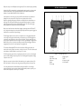
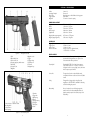
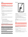
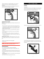
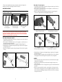
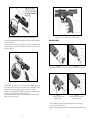
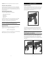
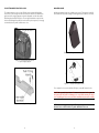
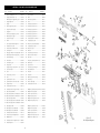
VP9 OPERATOR’S MANUAL 9 mm x 19 SAFETY RULES Please read this operator's manual before handling your firearm. The following safety rules are placed in this manual by HK as an important reminder that firearm safety is your responsibility. Firearms can be dangerous and can potentially cause serious injury, damage to property or death, if handled improperly. 1. Never point a firearm at anyone or in any direction other than a SAFE direction, i.e. down range. 2. Treat all firearms as if they are always loaded. 3. Keep your finger off the trigger and outside of the trigger guard until your sights are aligned on the target and you are ready to fire. 4. Keep your finger off the trigger and outside of the trigger guard while loading or unloading the firearm. 5. Keep your finger off the trigger and outside of the trigger guard while pulling the firearm out of the holster or while returning it to the holster. 6. Be sure of your target and the backstop beyond. 7. Never give a firearm to or take a firearm from anyone unless the action is open and the magazine and/or chamber are free of any ammunition or brass. 8. Be sure that the ammunition you are using is factory loaded, is of the correct caliber for the firearm in which it is to be used, and that it is not damaged in any way. 9. Before firing, remove the magazine from the firearm, lock the action open, make sure the chamber is clear of any ammunition or brass, and check the barrel of the unloaded firearm for any possible obstructions. 10. Before firing any firearm that is unfamiliar to you, make sure that you understand exactly how it functions. A lack of familiarity with the firearm can result in serious accidents. Attend a certified training course on any firearm which you intend to use or with which you are not sufficiently familiar. 11. Always wear hearing and eye protection when using your firearm. 12. Keep all body parts, especially the hands and fingers, away from the muzzle to avoid injury or burns. 13. Be sure that no part of either hand touches or interferes with the slide. The slide is moved backward by the recoil force of the pistol during firing and may cause serious injury. 14. Firearms should be locked and stored separately from ammunition and beyond the reach of children and/or any untrained individuals. 15. Avoid the use of any alcoholic beverages or drugs before or during your use of a firearm. 16. Discharging firearms in poorly ventilated areas, cleaning firearms, or handling ammunition may result in exposure to lead; a substance known to be associated with birth defects, reproductive harm and other serious injury. Have adequate ventilation at all times. Wash hands thoroughly after exposure. WARNING: A firearm has the capability of taking your life or the life of someone else! Be extremely careful with your firearm. An accident can occur at anytime and is almost always the result of not following basic safety rules. VP9 Operator’s Manual STOP! Know how to clear this pistol before attempting to operate. Clearing the Pistol - The VP9 Pistol is not considered “clear” or safe unless: 1. The magazine is removed from the pistol; 2. The slide is locked to the rear and; 3. The chamber is free of brass or ammunition. To Clear the VP9 Pistol: 1. Make sure fingers are outside of the trigger guard and the pistol is pointed in a safe direction at all times! 2. Remove magazine. Depress the magazine release lever and remove the magazine from the pistol. 3. Open and lock slide. While pointing the pistol in a safe direction, lock the slide open by pulling the slide rearward as you press the slide release upward. Watch for a cartridge or empty case to be ejected from the pistol. 4. Inspect chamber. Inspect chamber for the presence of a cartridge or empty case by: • Visually viewing chamber through open ejection port. • Physically inserting finger into chamber through ejection port to check for the presence of a cartridge or empty case. • Remove any cartridges or empty cases from the chamber or from within the pistol. The VP9 Pistol is now considered “Clear.” Heckler & Koch 5675 Transport Boulevard Columbus, Georgia 31907 USA Tel: (706) 568-1906 • Fax: (706) 568-9151 USA Website: www.hk-usa.com • Global Website: www.heckler-koch.com • Email: cs@ heckler-koch-us.com © Heckler & Koch USA (Heckler & Koch Inc. and Heckler & Koch Defense Inc.) May 2014, 3rd Edition/Aug. 2014 All rights reserved, specifications and models subject to change without notice. TABLE OF CONTENTS Safety Precautions & Clearing........................................................... Inside Cover Section 1 Introduction........................................................................................5 Section 2 Nomenclature....................................................................................7 Section 3 Specifications.....................................................................................9 Section 4 Function & Operation .....................................................................10 Cycle of Operation .........................................................................10 Safety Features.................................................................................11 Section 5 Instructions for Use..........................................................................12 Clearing Procedure..........................................................................12 Installation of Backstraps and Grip Panels.......................................13 Ammunition.....................................................................................14 Filling & Emptying the Magazine . ..................................................14 Loading ...........................................................................................15 Sights and Aiming............................................................................16 Firing................................................................................................16 Unloading .......................................................................................17 Selection & Use of a Holster............................................................18 Storage & Transport ........................................................................18 Section 6 Disassembly & Assembly ................................................................19 Disassembly.....................................................................................19 Magazine Disassembly.....................................................................20 Assembly . .......................................................................................21 Magazine Assembly.........................................................................23 Function Check ...............................................................................24 Section 7 Cleaning & Maintenance ................................................................25 Cleaning . ........................................................................................25 Inspection .......................................................................................26 Lubrication ......................................................................................27 Troubleshooting Problems & Repair ...............................................28 Warranty Registration Information...................................................28 Section 8 VP9 Accessories.......................................................................................29 Section 9 VP9 Parts List ..........................................................................................32 Exploded View.........................................................................................33 Firearms Service Record . ......................................................................34 SECTION 1 INTRODUCTION The VP9 was developed by Heckler & Koch to meet the need for a safe, robust, ergonomically enhanced, striker fired handgun. Incorporating a variation of the well-proven, modified Browning link-less short recoil system of operation, the VP9 striker fired design ensures a consistent trigger pull weight from the first shot to the last. Safety features abound on the VP9 and include a unique side mounted drop safety for the firing pin. The frame incorporates a trigger mounted safety that prevents accidental discharge from impact if the VP9 is struck or dropped, and a disconnector ensures that the slide must be in battery for the VP9 to fire. The take down lever acts as a disassembly safety and precludes the VP9 from being disassembled unless the magazine is removed from the magazine well. If cocked, the firing pin is also decocked as the take down lever is rotated forward. The design of the VP9 allows the operator to visually assess the status of the firearm by featuring an extractor that also functions as a loaded chamber indicator. A red colored insert at the back of the firing pin indicates if the firing pin is in the cocked or uncocked mode. Witness holes on the back of the magazine housing allow the operator to view the amount of ammunition present by means of a quick glance. VP9 controls are completely ambidextrous. Slide releases are present on both sides of the frame, as well as an easy-to-access ambidextrous magazine release on the rear, bottom portion of the trigger guard. Ambidextrous finger recesses, located on the bottom sides of the magazine well, allow the operator to achieve purchase on the magazine’s floor plate in the unlikely event that the magazine does not drop free when the extended flanges on the magazine release are activated. The VP9’s high strength polymer frame includes a unique ergonomic handgun grip design consisting of interchangeable grip panels and backstraps, as well as a dustcover with a standard Picatinny rail interface. The handgun grip design includes three changeable backstraps and six side panels— accommodating all hand sizes. Molded finger grooves in the front of the pistol’s grip also instinctively position an operator’s hand for optimal shooting. Only HK handguns have such a customized grip. Milled from a solid block of high carbon steel and then enhanced with a corrosion resistant nitro-carburized finish, the slide on the VP9 features non-radioactive luminous sights as standard that are adjustable for both windage and elevation, front and rear slide serrations, as well as extensions on the back of the slide. Designated as charging supports, this new patented HK feature allows operators of different sizes and statures — and shooters with reduced hand strength to obtain better gripping leverage for racking the slide rearward, facilitating smoother and easier manipulation of the slide during clearing or reloading. Heckler & Koch, famous for small arms construction and technology, has outfitted the VP9 with a cold hammer forged barrel and a polished feed ramp. The barrel — made from canon grade steel — ensures long service life. Similar barrels on HK P30 9 mm models have fired more than 90,000 rounds in endurance tests in 2010. The polygonal bore profile, with no traditional lands-and-grooves rifling, contributes to longer service life as well as a slight increase in muzzle velocity. 4 5 VP9 pistols use proven HK P30 pistol steel magazines (15 and 10-round capacity available). section 2 nomenclature Quality of the VP9 is maintained by ensuring that the design is tested in accordance with both the North Atlantic Treaty Organization’s (NATO) AC/225 D/14 and the National Institute of Justice’s (NIJ) Standard 0112.03 certifications. In development for more than four years, the VP9 is Heckler & Koch’s first striker fired handgun since the renowned P7 series pistols were introduced in the 1980s. Experience gained by HK engineers with the recent P30 pistol had a direct influence on the design of the VP9, but the VP9 breaks new ground with its integration of a unique striker firing system with an enhanced HK “light pull” trigger. The net result is trigger quality unequaled in any production striker fired handgun. HK pioneered the first modern striker-fired handguns, producing both the VP70 and P7 series, designs that impacted several models by HK competitors. But a superior trigger has eluded most recent striker fired pistol designs. The VP9 trigger surpasses those found on competitors. It has a short, light take-up with a solid, single action type break followed by a short positive reset. The VP9 trigger has a consistent pre-travel pull with a positive wall and crisp break. Typically, striker fired guns have a pre-travel pull that increases in weight as a shooter goes through the trigger stroke. With the VP9, you have a less than noticeable pre-travel pull until the trigger reaches the engagement point of the fire control parts prior to trigger break. The extended Picatinny MIL-STD-1913 rail molded into the VP9’s polymer frame can mount a wide variety of lights, laser aimers, and other accessories. The rail has been tested and certified to handle mounted accessories up to 5.6 ounces. The VP9’s proprietary captive flat recoil spring helps reduce the recoil forces effecting the operator and the handgun, improving shooter control during rapid firing and prolonging component service life. VP9 pistols are made in Heckler & Koch’s Oberndorf factory in southwest Germany. The VP9 is well suited for civilian sport shooting, security, military, and law enforcement use. Figure 1 — VP9 (left side view) 1 Rear sight 6 Trigger guard 2 Slide release, right 7 Frame 3 Extractor 8 Grip panel, right 4 Barrel 9 Serial number 5 Front sight Covered by Heckler & Koch’s limited lifetime warranty, the HK VP9 is a solid design engineered with the famous long-term durability that make HK products especially costeffective when subjected to total life cycle cost analysis. 6 7 SECTION 3 Specifications Figure 2 — VP9 (right side view) 1 2 3 4 5 6 7 Slide Disassembly lever Slide release, left Charging support, ambidextrous Back strap Grip panel, left Magazine 8 Magazine catch 9 Trigger 10 Trigger safety 11 Picatinny-rail 12 Follower 13 Magazine lips 1 Chamber 2 Trigger bar 3 Main spring 4 Ejector 5 Firing pin safety 6 Firing pin 7 Slide plate 8 Catch 9 Control surface on barrel shoulder 10 Locking block 11 Stop in frame 12 Recoil spring Caliber Operating Principle Action Type Trigger System Magazine 9 mm x 19 Short recoil Browning type, modified linkless locking system Striker fired 15 round or 10 round capacity Dimensions & Weight Length Width Height Barrel Length Sight Radius 7.34 1.32 5.41 4.09 6.38 Weight (with empty magazine) Weight (empty magazine) 26.56 ounces / 753 grams 3.28 ounces / 93 grams Other Data Trigger Pull Trigger Travel Return Travel Barrel Profile/Twist 5.4 pounds / 24 Newtons .24 inches / 6 mm .12 inches / 3 mm Polygon, 6 grooves, right-hand twist, 1 in 9.8 inches / 1 in 250 mm Miscellaneous Warranty inches inches inches inches inches 186.5 mm 33.5 mm 137.5 mm 104 mm 162 mm Limited Lifetime Warranty for the original retail (commercial/civilian) purchaser, one year for law enforcement and military customers Picatinny Rail Extended MIL-STD-1913 rail with four segments located under dust cover — rated to 5.6 ounces / 160 grams load for accessory light, lasers, and aimers with no impact on performance Service Life Test guns have fired more than 10,000 rounds, comparable HK 9 mm models have achieved 91,000 rounds Safety Firing pin block, trigger latch safety. Pistol and magazine are ACC225 NATO and NIJ0112.03 safety certified including drop tested Disassembly No tools required for user field strip, magazine must be removed for disassembly. Minimal tools (simple punches) required for detailed, depot level disassembly Figure 3 — VP9 Cutaway View 8 / / / / / 9 SECTION 4 FUNCTION AND OPERATION Cycle of OPERATION The cycle of operation is a reoccurring sequence of mechanical events which takes place in the operation of a self-loading firearm. The sequence for the VP9 begins with a loaded magazine inserted into the magazine well with the slide locked back to the rear. 1. Feeding: Removal of a round from the magazine Depressing either side of the ambidextrous slide release or pulling slightly back on the charging supports allows the recoil spring to expand, driving the slide forward. The feed pawl, an extrusion that is located on the bottom of the slide, passes between the feed lips of the magazine tube, striking the top round and pushing it towards the chamber. The projectile then contacts the barrel’s feed ramp, allowing the base of the cartridge to pivot upwards on the slide’s breech face. 2. Chambering: Placing and seating the round into the chamber of the barrel The recoil spring continues to expand, driving the slide forward and the slide positions the cartridge into the chamber. The base of the cartridge continues to pivot upwards as the slide mounted extractor engages the cartridge’s extractor rim. Chambering is complete by the time the barrel starts to move when the slide comes in contact with the back of the barrel’s locking block and starts to pivot the barrel upwards and forward. 3. Locking: Closing and locking of the breech mechanism prior to the shot As the slide is moving forward, the slide’s breech face contacts the extension on the back of the barrel’s locking block and thus pivots the barrel upward until the stepped forward edge of the barrel locking block engages the forward edge of ejection port. As the slide locks into position, the frame mounted disconnector is allowed to pivot upwards into a corresponding relief cut milled on the inside of the slide, thus allowing the trigger bar access to sear release catch. The locking phase is complete when the slide reaches its limit of forward travel. 4. Firing:Ignition of the cartridge’s primer and propellant As the operator pulls back on the trigger, the trigger safety latch pivots upwards, thus allowing the trigger to be pulled back towards the rear. The trigger bar, connected to the trigger moves back as well, allowing an engagement surface on the trigger bar to pivot the spring loaded firing pin safety to the side which allows the firing pin to move forward once the trigger is pulled. The trigger bar continues to move to the rear until the back of the trigger bar contacts and then presses downward on the sear release catch. The sear release catch, in turn, pushes downward on the catch, disengaging the catch from the firing pin and then allowing the firing pin to move forward, being driven by the expansion of the firing pin spring. The tip of the firing pin contacts and then pierces the primer. The primer detonates which, in turn, ignites the propellant. The projectile, separated from the cartridge case, is forced down the barrel by the expanding gases and is stabilized by the polygonal rifling located inside the bore. 5. Unlocking: Removal of any blocking mechanism to allow the opening of the breech The resultant force of the cartridge firing produces an impact on the slide and barrel, initially pushing both the slide and barrel back in unison. The slide’s ejection port pushes back on the barrel locking block and after approximately 4.5 millimeters of travel, pivots the barrel downward until the barrel’s angular locking surface engages the contact surface on the frame mounted locking block. 6. Extracting: Removal of the fired cartridge case or live round from the chamber With the barrel now retained by the locking block, the slide continues to move towards the rear. The extractor pulls the fired cartridge case or live round from the chamber. 7. Ejecting: Expulsion of the fired cartridge case or live round from the firearm The extractor engages the cartridge case’s extractor rim as the barrel travels to the rear. The extractor creates a pivot and the frame mounted ejector creates a contact point, as the slide rakes the cartridge case against the ejector, allowing the ejector to expel the cartridge case out through the ejection port. 8. Cocking: Resetting of the trigger mechanism to allow subsequent shots to be fired In the first few millimeters of rearward travel, the slide passes over the disconnector and presses it downward, thus precluding the trigger bar from depressing the sear release catch and immobilizing the firing pin system. As the slide continues to move back towards the rear, the frame mounted catch engages and pushes back on the lug mounted underneath the firing pin, thus compressing the firing pin spring and cocking the firing pin. SAFETY FEATURES — The VP9 incorporates the following safety features: 1. Firing Pin Safety The slide mounted firing pin safety helps prevent accidental discharge from impact if the VP9 is struck or dropped. When at rest, the back of the spring loaded safety pivots towards the center of the slide and engages a tang that extends downward on the bottom of the firing pin and thus blocks the firing pin from moving forward in the firing pin tunnel. Once the trigger is pulled, an engagement surface on the trigger bar pivots the firing pin safety to the side and allows the forward movement of the firing pin. 2. Trigger Safety The frame mounted trigger safety also helps prevent accidental discharge if the VP9 is struck or dropped by blocking the rearward movement of the trigger assembly thereby immobilizing the trigger bar, unless the entire trigger is pulled back to the rear. With the trigger bar unable to press downward on the sear release catch, the catch remains upright and holds the cocked firing pin assembly in place. 3. Disconnector The frame mounted disconnector ensures that the VP9’s slide must be in battery before allowing the trigger bar access to disengage the sear release catch and thus preclude the release of the firing pin. When out of battery, the disconnector is pushed downward by the slide. In battery, a relief cut milled on the bottom of the slide allows the disconnector to pivot upwards and allows the trigger bar to travel rewards to disengage the sear release catch. 4. Disassembly Safety The disassembly safety ensures that the magazine must be removed from the magazine well, the chamber be cleared, and the firing pin decocked prior to disassembly. The dismounting safety is pivoted upwards by the presence of a magazine (loaded or unloaded) and thus blocks the operation of the disassembly lever. When the magazine is removed, the dismounting safety pivots downward and allows the disassembly lever to be rotated forward. The bottom of the barrel locking block prohibits the operation of the disassembly lever when the slide is forward. Having to lock the slide to the rear prior to manipulating the disassembly lever ensues that any round present in the chamber is extracted and ejected. The activation of the disassembly lever also decocks the firing pin by repositioning the trigger bar slightly forward. The slide then presses downward on the trigger bar which disengages the catch from the firing pin. UC TIONS FOR USE 10 11 SECTION 5 Instructions for use CLEARING PROCEDURES 1. Point the muzzle of the VP9 in a safe direction. Ensure the muzzle of the VP9 is pointed in a safe direction and that the operator’s fingers are off the trigger and outside the trigger guard. 2. Remove the magazine. Depress either side of the ambidextrous magazine release and remove the magazine from the magazine well. 3. Open and lock the slide to the rear. Grasping the charging supports, rack the slide to the rear while keeping the muzzle pointed in a safe direction. Pivot upwards on either of the ambidextrous slide release levers and lock the slide to the rear. Watch for a cartridge or empty case to be ejected out through the ejection port. 4. Inspect the chamber. Inspect the chamber for the presence of a cartridge or empty case by: 1. Visually inspecting the chamber through the open ejection port. 2. Physically inserting a finger through the ejection port and sweeping the chamber and feed ramp area. 3. Removing any cartridges or empty cases from the chamber or from within the VP9. Figure 5 Installing backstrap and grip panels Figure 6 Push the grip panels forward into the guide rails on the frame Installation of the Backstrap and Grip Panels 1. Using a 2.8 mm pin punch, remove the pin (clamping sleeve) holding the backstrap in postion. Choose the combination of backstrap and grip panels that provide the most comfortable fit for the operator (See Figure 5). 2. Install the two grooves on the inside of each grip panel onto the corresponding tongues located on the outside of the frame (Figure 5 and Figure 6) and push the panels forward until they seat flush into the frame. 3. Seat the backstrap on to the back of the frame and push upwards until the mounting surface for the pin/clamping sleeve on the backstrap aligns with the mounting surface for the pin/clamping sleeve on the frame. 4. Drift the pin/clamping sleeve into position and capture the backstrap to the frame using the pin punch. Figure 4 — Clearing the VP9 Pistol 12 13 AMMUNITION Filling the Magazine WARNING: HK specifically disclaims any responsibilities for any damage or injury that should occur because of, or as a result of, the use of faulty, remanufactured, or reloaded (hand loaded) ammunition, or of cartridges other than those for which the pistol was originally chambered for. The HK VP9 pistol is designed to fire quality, factory-loaded ammunition, loaded to NATO or SAAMI (Sporting Arms and Ammunition Manufacturers’ Institute) specifications for use specifically in handguns. The following guidelines should be considered when selecting the correct ammunition for your pistol: 1. Be sure the ammunition you have chosen is compatible with your pistol-proper caliber, cartridge, bullet weight, etc. Caliber markings on the VP9 pistol appear on the left side of the slide and on the barrel locking block, visible through the ejection port on the right side of the slide. 2. Prior to loading the magazine and chamber, carefully inspect all cartridges for the following abnormalities: • Cracked, split, dirty or corroded cases • Improperly seated projectiles and/or primers • Damaged projectiles. 3. Do not attempt to fire a cartridge in which the projectile has been forced back into the case. Upon firing, this condition may result in increased chamber pressure above safe limits. 4. Do not fire ammunition through a pistol that: • Is foreign and/or outdated military surplus • Is assembled with corrosive primer and/or propellant • Is exposed to oil, grease, water or direct sunlight. If possible, remove contaminants before use and cool down ammunition exposed to direct sunlight or heat. (Expo sure to sources of heat could raise the chamber pressure of the cartridge above safe limits.) • Is loaded specifically for use in submachine guns. CAUTION: HK firearms are designed to function with quality, manufactured brasscased ammunition. Use of steel or aluminum-cased cartridges is not recommended and could adversely affect safe and reliable functioning. Use of cast-lead bullets is also not recommended. NOTE: HK handguns are safe for use with new, high-quality U.S. factory ammunition manufactured to SAAMI specifications. For further information on ammunition selection, contact HK Customer Service at 706-568-1906, email: [email protected]. Filling and Emptying the Magazine NOTE: Do not attempt to load more than the prescribed number of cartridges into the magazine. Do not alter the shape of the magazine housing, follower or spring. To do so may cause stoppages or the magazine may not seat properly in the pistol. 14 Figure 7 — Loading the magazine 1. Hold the magazine in the non-firing hand with the back side of the magazine resting against the palm. 2. Using the firing hand, hold a cartridge between the index finger and thumb with the projectile facing the palm. 3. Press the rim of the cartridge down against the forward edge of the magaz ine follower or on the top cartridge already in the magazine. 4. Slide the cartridge back into the magazine under the feed lips. 5. Repeat steps 1-4 until the magazine is full. The viewing holes in the back of the magazine allow the operator to confirm the number of cartridges present within the magazine. Emptying the Magazine - Exert pressure with a finger on the base of the cartridge and push each cartridge forward out of the magazine one at a time until the magazine is empty. Loading WARNING: Forcefully inserting a loaded magazine into many pistols may cause the pistol’s slide to close, chambering a cartridge and making the pistol ready to fire. When inserting a magazine, always be sure the VP9 pistol is pointed in a safe direction with your fingers off the trigger and outside the trigger guard. Failure to do so could cause you to unintentionally fire the pistol, resulting in serious injury or death. Administrative Loading - Used to initially load the pistol before it is to be fired. Slide rearward or forward, chamber empty. 1. Make sure fingers are outside of the trigger guard and the pistol is pointed in a safe direction at all times! 2. Insert magazine - Insert the magazine firmly into the frame. Tug on the magazine to insure that it is fully seated and engaged. 3. Chamber a cartridge - Chamber a cartridge by depressing the slide release or by pulling the slide fully to the rear and releasing it. Do not ride the slide forward! 15 sights and aiming The VP9 is equipped with a three dot sighting system, similar to those first introduced by HK on the P7 series pistol in the 1970s. The sights are adjustable for both windage (by drifting) and elevation (by replacement of the front sight). Sights are installed and aligned by HK technicians at the factory. Only an HK certified armorer should adjust or replace the VP9 sights. Figure 8 shows correct sight alignment, Figure 9 shows common sight errors. 1. Acquire the proper sight alignment and sight picture (see Figure 8). 2. Control Breathing 3. Gradually squeeze the trigger straight to the rear while attempting to avoid disruption to the sight picture and alignment. 4. Practice good follow-through techniques by maintaining proper sight picture and trigger squeeze until after the firearm has discharged. NOTE: The VP9 is test fired for accuracy by ensuring the point of aim equals point of impact at 25 meters (27.3 yards). Individual results concerning accuracy and/or shot placement are affected by such factors as stance, grip, ammunition, and engagement range. Figure 10 — Two-handed grip Figure 8 — Correct sight alignment The VP9 employs a striker fired trigger system that cocks the firing pin as the slide recoils to the rear to extract and eject the fired cartridge case, thus ensuring a consistent trigger pull on all shots, from the first to the last round in the magazine. Figure 11 & 12 show comparison of the cocked and uncocked firing pin positions, the rear, RED colored portion of the firing pin is visible if the VP9 is cocked and ready to fire. Figure 11 — Firing pin cocked Figure 12 — Firing pin uncocked UNLOADING The slide on the VP9 is locked back after the last round is fed from the magazine by the spring loaded magazine follower engaging a tab located on the inside of the left hand side release lever. As the slide release lever is pivoted upwards, the back of the lever engages a cut-out on the bottom of slide and locks the slide to the rear. Figure 9 — Common sight alignment errors FIRING WARNING 1. Be sure of your target and what’s behind it! A bullet from a pistol travels as far as a mile. It can easily penetrate wood or plasterboard walls or even a car door. 2. Be sure that your hands and all parts of your body are kept away from the muzzle of your pistol at all times! 3. Always wear eye and ear protection when firing the pistol. 16 The magazine can then be removed by depressing either side of the ambidextrous magazine release and both a visual and a physical inspection can be performed on the chamber/feed ramp area. In the event that the operator wishes to cease firing and unload the firearm before the last round in the magazine is fired then the standard clearing procedure for the VP9 is recommended: 1. Point the muzzle of the VP9 in a safe direction with the operator’s fingers off the trigger and outside the trigger guard. 2. Remove the magazine by depressing either side of the ambidextrous magazine release and remove the magazine from the firearm. 17 3. Rack and lock the slide to the rear by pressing upwards on either or both of the ambidextrous slide release levers and the slide is pulled back towards the rear (See Figure 13). 4. Perform both a physical and visual inspection of the chamber/feed ramp area and remove any live rounds or fired cartridge cases if applicable. SECTION 6 DisASSEMBLY & ASSEMBLY DISASSEMBLY 1. Clear the VP9! 2. With the slide still locked to the rear and the magazine removed, rotate disassembly lever, located on the left hand side of the frame, forward until the lever is pointing downwards to approximately the six o’clock position (see Figure 14): Figure 13 — Unloading Selection and use of a Holster Selection - When selecting a carrying holster for the VP9 pistol, it is important to consider the following points: 1. The holster must not make contact with or actuate any of the operating controls. This includes the slide release, magazine release lever, and most importantly the trigger. The design of the holster must also not actuate these controls when the pistol is carried in, drawn from or returned to the holster. 2. The holster should not cause the slide to move (unlock) when the pistol is returned to the holster. 3. Accommodations must be provided in the holster for any accessories that might be present on the pistol. 4. Choose a holster designed specifically for a VP9 pistol. A list of manufacturers that make holsters for a variety of HK pistols is available at the Heckler & Koch website or by contacting HK Customer Service. Returning the pistol to the holster - The VP9 pistol must be made “Safe” (or cleared) prior to returning it to the holster. The pistol is considered safe to return it to the holster when: 1. All fingers are off of the trigger and out of the trigger guard. 2. The pistol is “clear.” WARNING: The pistol must never be returned to the holster unless the above procedures have been followed or injury or death could occur. Storage and Transport 1. Store or transport the pistol and its components clean and lubricated. 2. Store and transport the pistol without cartridges in the chamber, magazine or in the storage container. 3. Store and transport the pistol with the slide forward and the hammer down (uncocked). 4. Clean and lubricate the pistol and its components at least every twelve (12) months during storage. 5. Store the pistol and its components in a clean, dry, dust-free environment with regulated temperat ure controls. 6. Store the pistol and ammunition separately under lock and key. 18 Figure14 — Rotating the disassembly lever 3. Push the slide forward, removing the slide from the top of the frame (see Figure 15). Figure15 — Removing slide from frame by pushing it forward 4. Turn the slide upside down and carefully push the recoil spring forward and out to either the left or right hand side, separating the recoil spring from the barrel and slide (see Figure 16). Figure 16 — Removing the recoil spring 19 Disassembly of 10-round magazines: 1. Using a blunt, pointed instrument, depress the locking insert detent located in the floorplate and hold it there (see Figure 22). 2. Place a portion of either hand over the base of the magazine to control the release of the magazine spring and locking insert. 3. With the locking insert detent still depressed, squeeze the floor plate locking tabs located on the right and left sides of the magazine (see Figure 23). 5. Pivot the barrel slightly forward and press downward on the barrel locking block through the ejection port, separating the barrel from the slide. MAGAZINE DISASSEMBLY NOTE: The VP9 pistol uses readily available 9 mm HK P30 pistol magazines, either 15-round or 10-round capacity. Figure 17 15-round and 10-round magazines Figure 18 Depressing locking detent in floorplate Figure 19 Slide the floorplate forward CAUTION: Beware of the spring tension exerted by the magazine spring while removing and installing the magazine floorplate. Keep the base of the magazine pointed in a safe direction (away from the face and eyes) at all times during disas sembly and reassembly and wear eye protection. Disassembly of high-capacity magazines 1. Using a blunt, pointed instrument, depress the locking detent located in the floorplate and hold it there (see Figure 18). 2. Place a portion of either hand over the base of the magazine to control the release of the magazine spring and locking plate. 3. Slowly slide the floorplate forward off of the magazine housing (see Figure 19). 4. Gradually allow the locking plate and magazine spring to expand out of the magazine housing (see Figure 20). 5. Remove the locking plate, magazine spring and magazine follower from the magazine housing. Figure 22 Depress locking insert detent Figure 23 Releasing magazine components Figure 24 Removing locking insert and spring Figure 25 10-round magazine components 4. Gradually allow the locking insert and magazine spring to expand out of the magazine housing (see Figure 24). 5. Remove the locking insert, magazine spring and magaz ine follower from the magazine housing. Figure 25 shows all the magazine components for 10 round magazines. Figure 20 Removing locking plate and spring Figure 21 15-round magazine components 20 ASSEMBLY 1.Turn the slide upside down and insert the barrel into the slide with the barrel’s angular locking surface facing upwards. 2.Pivot the barrel back towards the rear until the barrel’s locking block snaps into the slide’s ejection port. 3.Insert the pronged end of the recoil spring into the tang on the slide that extends below the muzzle. 4.Push the recoil spring forward into position, compressing the recoil spring, then pivot the back of the recoil spring guide rod on to the stepped mounting surface located on the front of the barrel locking lug (see Figure 26). Ensure the front of the recoil spring is facing forward in the slide. 21 Figure 26 — Reassembling the recoil spring onto the barrel and side 5. Ensure that no magazine is present in the magazine well and that the disassembly lever is in the down position. 6. Mount the slide onto the frame, ensuring that the recoil spring is centered underneath the barrel, and that the rails on the frame are inserted into the grooves on the bottom of the slide (see Figure 27). Figure 28 — Pivot the disassembly lever counter clockwise Magazine Assembly Figure 29 Insert the follower, spring, and locking insert Figure 30 Push the locking insert above the cutouts Figure 27 — Mounting the slide on the frame 7. Pull the slide back towards the rear. It might sometimes be necessary to push directly down on the back of the slide where the rear sight is located, to ensure that the rails on the rear frame insert properly engage the grooves on the bottom of the slide. 8. Continue to bring the slide back towards the rear as either of the ambidextrous slide release levers are pivoted upwards, thus locking the slide back. 9. Pivot the disassembly lever counter clockwise so that the lever lies horizontal to the bottom of the slide (see Figure 28). Figure 31 Insert the floorplate into the magazine housing Figure 32 Ensure the tabs on the floorplate seat onto the cutouts 1. Place the magazine follower onto the magazine spring with the end of the spring positioned on the left of the follower. 2. Insert the follower and magazine spring into the magazine housing as depicted in Figure 29. 22 23 3. Place the locking plate (locking insert) onto the protruding end of the magazine spring so that the rounded corners face toward the front of the magazine. 4. Push the locking plate into the magazine housing against the pressure of the magazine spring and hold it there. (Figure 30) 5. On 10-round magazines, push the floorplate up onto the base of the magazine housing until the locking tabs engage in the sides of the housing. (Figure 31) 6. Check to see if the locking tabs on the floorplate are securely locked into the housing and the locking detent on the locking plate fits within the hole in the floorplate. (Figure 32) On all magazines, check the magazine for proper assembly by insuring that the follower slides up and down freely within the magazine housing and with spring tension. Also check that the magazine follower rises within the magazine housing to be nearly flush against the bottom of the magazine feed lips. FUNCTION CHECK It is essential that a function check be performed on the VP9 after reassembly to ensure that the firearm’s components have been correctly installed. 1. Clear the VP9! 2. Rack the slide towards the rear about three or four times in quick succession, ensuring that fingers are off the trigger and outside the trigger guard. The slide should be able to pivot back and forth, under the tension of the recoil spring, without binding or locking up. 3. Return the slide to battery and check the cocking status of the firing pin. The red cocking indicator should be visible through the witness hole on the slide plate. 4. With an unloaded firearm and the muzzle in a safe direction, pull the trigger and dry fire the VP9. While maintaining backward pressure on the trigger, observe the witness hole on the side plate. The firing pin should now be in the uncocked position and the red indicator should not be visible. 5. Rack the slide to the rear and release, again keeping constant tension on the trigger until the slide returns to battery. The firing pin should be returned to the cocked position with the red indicator once again visible in the side plate once the trigger is allowed to reset. 6. Insert an empty magazine in the magazine well and rack the slide to rear. The slide should lock on an empty chamber. Contact the Heckler & Koch Customer Service Department at TEL: 706-568-1906 or EMAIL:[email protected] if you encounter any problems in attempting to disassemble, assemble, and/or conduct a function check on the VP9 pistol. 24 SECTION 7 CLEANING & MAINTENANCE CLEANING NOTE: The service life and performance of your HK VP9 pistol is dependent upon the correct handling and proper care by the operator. Materials Required - At a minimum, we suggest the following materials to properly clean the VP9: • Cleaning rod with handle and patch holder • Nylon toothbrush • Bronze bristle bore brush (in the appropriate caliber) • Cleaning patches (in the appropriate caliber) • Lint-free wiping rag • Cleaning solvent/lubricant • Cotton swabs CAUTION: Use safety goggles when using solvents and exercise care if using compressed air. Handgun cleaning kits are available from HK for thorough cleaning of pistols and other firearms. Visit the HK-USA webshop or contact HK Customer Service. Cleaning Intervals - Normal and Major are the two types of operator cleaning for the VP9 pistol. Normal Cleaning - Performed after each firing or every twelve (12) months. Major Cleaning - Often referred to as “detailed cleaning.” Performed after the firing of 500 cartridges or when the pistol is exposed to, or laden throughout, with sand, dust, water (es pecially salt water) or other visible contaminants or foreign matter. Normal Cleaning CAUTION: Do not use a stainless steel bore brush which can scratch the polygonal bore and reduce accuracy. Slide - • Gently scrub all internal surfaces of the slide using the nylon toothbrush moistened with solvent. • Remove all loose fouling from all surfaces of the slide using a rag and cotton swabs. Recoil spring assembly • Remove all visible fouling using solvent, a nylon toothbrush or a rag and cotton swabs. Barrel (with locking block) • Moisten a bronze bore brush with solvent and scrub the bore from chamber to muzzle at least six (6) passes, back and forth. • Remove the loose fouling from the bore using cleaning patches. • Gently scrub the exterior of the barrel and locking block with the nylon toothbrush moist ened with solvent. • Remove all loose fouling from the exterior of the barrel using a rag and cotton swabs. Frame • Gently scrub all internal surfaces where carbon fouling is present using the nylon tooth brush moistened with solvent. Concentrate on the area normally covered by the slide. • Using a rag and cotton swabs, remove all loose fouling from all areas of the frame. 25 Magazine • Gently scrub the top of the magazine, concentrating on the follower and feed lips, using the nylon toothbrush moistened with solvent. • Using a rag and cotton swabs, remove all loose fouling from all surfaces of the magazine. Lubrication Major Cleaning - Major Cleaning is the same as normal cleaning except that: • The magazine is disassembled for cleaning. • All parts should be rinsed with or immersed in solvent and thoroughly scrubbed with a nylon brush. The parts can then be dried using compressed air or with a rag and cotton swabs. NOTE: All parts of the VP9 pistols can be immersed in any cleaning solvent that is safe to put your hands into, including ultrasonic cleaning solution. Use of ultrasonic cleaning machines can result in the unwanted removal of colored reference markings of the frame, extractor and control lever (where applicable). Use of ultrasonic cleaning is normally not necessary or recommended when using standard ammunition in HK pistols with less than 10,000 rounds of service. All components should be thoroughly dried after being immersed in solvents of any kind before reassembly and all of the firearm’s critical components should be lubricated in accordance with the applicable operator/maintenance instructions after being thoroughly dried. For special cleaning recommendations under extreme conditions, please contact HK Customer Service. Inspection During and after cleaning, visually inspect the pistol and its components for any irregularities that may cause problems or stoppages during operation. Generally, you should keep a watchful eye out for the discrepancies listed below. Always clear the pistol before conducting your inspection! Check for: • Damaged or missing parts • Improper assembly or function • Absence of free movement, where applicable • Absence of spring tension, where applicable • Unaccustomed looseness • Parts exhibiting signs of cracks, burrs, dents or obvious signs of damage or stress • Presence of stops or tactile clicks, where applicable • General overall cleanliness • Presence of sufficient lubrication • Presence of corrosion or degradation of surface finish. CAUTION: HK pistol designs represent an optimization of a combination of safety, speed of deployment, accuracy, dependability, and durability. Do not attempt to make an HK pistol “better” by altering any of its components. Altering any part of the pistol or magazine may cause injury or death and will also void any HK warranty on the product. Figure 33 — Lubrications Points (in red) Metal surfaces of the VP9 pistol are treated with HK’s special corrosion and wear-resistant finish. This surface treatment does not completely reduce the friction between moving parts and it is recommended that a lubricant be applied to the pistol to ensure proper functioning. Any type of high-quality, medium-weight lubricant (oil) specifically designed for use on firearms will work well on the VP9. Do not use lubricants that boast of their ability to penetrate metal as these substances may deaden primers. Figure 33 shows areas on the pistol requiring particluar attention to lubrication. Where and How Much No Lube - Surface is dry and not slippery to the touch. • All plastic and rubber components • Ammunition • Optronics (lights and aimers) Light Lube - A finger run across the surface yields little or no lube. • Bore, chamber and exterior of barrel • All metal parts • All internal parts in slide and frame • Magazine spring • Recoil spring assembly • VP pistol metal magazine housing, where applicable Medium Lube - A finger run across the surface yields some lube, but lube does not run down surface when it is held in a vertical position. • Barrel locking block • Slide rails and grooves • All operating controls • Locking insert and guiding part in frame • Extractor 26 27 Heavy Lube - Lubrication runs down the surface when it is held in a vertical position. SECTION 8 VP9 Accessories No heavy lube is required on the VP9 pistols. Rail Mounted Accessories Re-apply lubricant periodically during firing as it burns off from the heat. Apply lubricant using a clean shaving brush, cotton swabs, patches or rag. A spray bottle of lubricant also works well when using compressed air to circulate the lubricant into all parts and to remove the excess from the pistol. The VP9 has a full length MIL-STD-1913 (Picatinny) rail molded into the front, lower portion of the frame (dust cover). This rail allows the operator to mount a wide variety of lights, lasers aimers, and additional accessories to the handgun by means of the simple and proven Picatinny interface system (see Figure 34). Troubleshooting Problems and Repair Common causes of problems that are often overlooked include: • Fouled or improperly lubricated pistol • Bad ammunition • Damaged magazines • Operator error If your VP9 pistol still fails to function, please contact HK Customer Service at 706-5681906 for the name and address of your nearest HK Authorized Repair Facility. Law enforcement users, contact your unit armorer or HK Customer Service. NOTE: If after reviewing this manual you still have questions, please contact HK Customer Service at 706-568-1906 or by email: [email protected]. Warranty Registration New HK firearms are covered by Heckler & Koch’s Limited Lifetime Warranty. Warranty registration is now on-line. To register your new HK firearm go to: http://hk-usa.com/warranty/register.html If you don’t have access to the internet, contact HK Customer Service, TEL: 706-568-1906, EMAIL: [email protected] to obtain a warranty card by mail. Figure 34 — Accessory laser aiming module mounted on VP9 To avoid damage to the accessory and the VP9, carefully follow the instructions of the manufacturer for installing, operating, and removing accessories from the mounting rails. Always ensure the VP9 pistol is “clear” and unloaded before installing or removing accessories. NOTE: Weight of any frame (dust cover) mounted accessories should not exceed 5.64 ounces (160 grams) to ensure reliable function. Most lights, laser aimers, and similar accessories are installed by sliding them onto the front of the rail system while depressing a locking mechanism or clipping them on from the bottom. Again, follow the installation instructions of the accessory manufacturer. If encountering difficultly, please contact HK Customer Service to avoid damage to the pistol or the accessory. Figure 35 & 36 Installing accessory lights onto the rails 28 29 Flush Fitting Inserts for THE VP9 Slide Magazine Loader The charging supports on the rear of the VP9 slide can be replaced with flush fitting inserts. To do so, the rear sight must be removed from the dovetail notch. With the rear sight removed, the charging supports can then be slid upward out of the slide and the flush fitting inserts installed in their place. The rear sight should then be replaced in the slide dovetail. Although this modification can be made by the user/operator, it is strongly recommended that only an HK certified armorer do so. An HK pistol magazine loader is also available as an accessory. The magazine loader (HK article number 217 830 ) makes loading of all VP9 magazines easier and more convenient. Figure 39 — HK magazine loader for the VP9 Figure 37 — Rear sight must be removed to replace charging supports Figure 40 — Using the HK magazine loader For a complete list of accessories that fit the VP9 pistol, contact HK Customer Service. CAUTION: Improperly designed or installed accessories may result in damage to the rail system and/or the pistol. Such damage is not covered under warranty. Be certain to use only HK approved accessories and follow installation and precautions carefully. Figure 38 — Installing flush fitting inserts 30 NOTE: If after reviewing this manual you still have questions, please contact HK Customer Service at 706-568-1906 or by email: [email protected]. 31 SECTION 9 Item Description VP9 Parts List & Exploded view Part Number Item Description Part Number — Frame, complete (Item 1 - 37 .................. 226 274 — Slide, complete ....................................... 226 275 — Trigger, complete (Item 1 - 5) .................. 223 434 38 Barrel ....................................................... 243 453 1 Elbow spring for trigger safety catch ...... 260 459 39 Recoil spring, complete............................ 226 311 2 Trigger safety latch .................................. 260 458 40 Slide . ....................................................... 226 291 3 Trigger ..................................................... 223 435 41 Front sight, height 5.9 mm ...................... 227 711 4 Axle for trigger safety latch ..................... 975 812 41.1 Front sight, height 6.1 mm ...................... 234 327 5 Stop pin for elbow spring ........................ 967 947 41.2 Front sight, height 6.3 mm ...................... 234 328 6 Trigger bar ............................................... 223 438 41.3 Front sight, height 6.5 mm ...................... 234 329 7 Form spring for trigger bar, compl. ......... 260 502 41.4 Front sight, height 6.7 mm ...................... 234 386 8 Elbow spring for trigger.......................... 223 565 41.5 Front sight, height 6.9 mm ...................... 234 387 9 Stop bolt for trigger ................................ 260 440 42 Clamping sleeve for extractor ................. 988 891 10 Frame ...................................................... 223 431 43 Charging support, left ............................. 260 481 11 Catch spring for disassembly lever . ........ 260 453 43.1 Filler piece, left (not illustrated)................ 260 483 12 Slide release lever, left . ........................... 260 431 44 13 Pressure spring for slide release .............. 260 454 44.1 Filler piece, right ..................................... 260 482 14 Locking block .......................................... 260 501 45 Extractor .................................................. 218 314 15 Heavy type dowel pin for locking block .. 226 312 46 Pressure spring for extractor . .................. 218 315 16 Elbow spring for dismounting safety ....... 260 429 47 Extractor bolt for extractor ...................... 209 294 17 Dismounting safety . ................................ 260 430 48 Rear sight . ............................................... 234 323 18 Disconnector ........................................... 223 452 — Firing pin, complete (Item 49 - 53) .......... 223 516 19 Slide release, right ................................... 260 498 49 Main spring . ............................................ 226 233 20 Safety clamp ............................................ 260 436 50 Support sleeve ........................................ 260 488 — Trigger housing, compl. (Item 21 - 28) .... 223 436 51 Pressure spring for firing pin . .................. 260 487 21 Sear release catch . .................................. 226 319 52 Spring washer (2x) ................................... 260 489 22 Catch ....................................................... 226 317 53 Firing pin.................................................. 223 501 23 Pressure spring for catch.......................... 223 129 54 Slide plate ............................................... 260 504 24 Insert . ...................................................... 223 426 55 Elbow spring for drop safety ................... 260 478 25 Cylindrical pin for catch ........................... 973 785 56 Drop safety .............................................. 226 316 26 Cylindrical pin for sear release catch ....... 979 581 57 Axle for drop safety ................................. 226 314 27 Trigger housing `....................................... 260 464 58 Clamping sleeve for axle ......................... 976 574 28 Clamping sleeve for insert . .................... 978 170 29 Clamping sleeve for trigger housing ....... 975 715 — Magazine, complete (15-rd, Item 59 - 63) .234 316S 30 Grip panel, left (size M) ........................... 260 445 59 Magazine housing (15-rd)......................... 234 318 30.1 Grip panel, left (size S) not illustrated....... 260 442 60 Follower (15-rd and 10 rd)........................ 215 836 30.2 Grip panel, left (size L) not illustrated....... 260 449 61 Magazine spring (15-rd)............................ 215 118 31 Grip panel, right (size M).......................... 260 446 62 Magazine locking plate (15-rd)................. 215 844 31.1 Grip panel, right (size S) not illustrated.... 260 443 63 Magazine floor plate (15-rd) .................... 234 298 Back strap (size M) ................................... 260 444 Magazine, complete (10-rd).................... 229 750S 32.1 Back strap (size S) not illustrated ............. 260 441 Charging support, right ........................... 260 480 31.2 Grip panel, right (size L) not illustrated ... 260 450 32 Magazine housing (10-rd)......................... 215 848 32.2 Back strap (size L) not illustrated ............. 260 448 Follower (10-rd and 15-rd)........................ 215 836 33 Clamping sleeve for back strap................ 978 170 Magazine spring (10-rd)............................ 214 850 34 Pressure spring for magazine catch ......... 215 929 Magazine locking insert (10-rd)................ 215 850 35 Magazine catch ....................................... 260 500 Magazine floor plate (10-rd) .................... 227 947 36 Clamping sleeve for magazine catch ...... 988 891 37 Disassembly lever .................................... 260 427 32 Figure 37 VP9 Exploded Diagram 33 Weapon Type ________________ Serial Number ________________ Number of Cumulative Total Maintenance Date Rounds Fired of Rounds Fired User’s Name & Remarks ________________________________________________________________________________ ________________________________________________________________________________ ______________________________________________________________________________ ______________________________________________________________________________ ______________________________________________________________________________ ______________________________________________________________________________ ______________________________________________________________________________ ______________________________________________________________________________ ______________________________________________________________________________ ______________________________________________________________________________ ______________________________________________________________________________ ______________________________________________________________________________ ______________________________________________________________________________ ______________________________________________________________________________ ______________________________________________________________________________ ______________________________________________________________________________ ______________________________________________________________________________ ______________________________________________________________________________ ______________________________________________________________________________ ______________________________________________________________________________ ______________________________________________________________________________ ______________________________________________________________________________ 34 HKUSA708380-08122014 HECKLER & KOCH 5675 Transport Boulevard Columbus, Georgia 31907 United States of America Tel: (706) 568-1906 Fax: (706) 568-9151 USA Website: www.hk-usa.com HECKLER & KOCH D-78722 Oberndorf/Neckar Postfach 1329 Germany Tel: 011-49-7423/79-0 Fax: 011-49-7423/2280 Global Website: www.heckler-koch.com