1
DMI
Universal Multichannel Instrument
User Guide
MAN-00018 R5
If the equipment described herein bears the symbol, the said equipment complies with the applicable European Union Directive and
Standards mentioned in the Declaration of Conformity.
DMI OPERATING MANUAL
SAFETY INFORMATION
The following safety instructions must be observed whenever the DMI
instrument is operated. Failure to comply with any of these instructions or with
any precaution or warning contained in the DMI Operating Manual is in direct
violation of the standards of design, manufacture and intended use of the DMI
conditioner. FISO Technologies inc assumes no liability for the customer failure
to comply with this safety requirments. This product is not designed with
components of level of reliability suitable for use in life support or critical
applications.
IN NO CASE WILL FISO TECHNOLOGIES INC BE LIABLE TO THE BUYER, OR
TO ANY THIRD PARTIES, FOR ANY CONSEQUENTIAL DAMAGE OR INDIRECT
DAMAGE WHICH IS CAUSED BY PRODUCT FAILURE, MALFUNCTION, OR ANY
OTHER PROBLEM.
IMPORTANT SAFETY INSTRUCTIONS
When using any electrical appliance, basic safety precautions should be
followed, including the following:
WARNING
-
Use only the wall plug-in power supply or the power cord delivered with
your DMI instrument and verify that the voltage specifications indicated on
the wall plug-in power supply (or indicated near by the panel power
connector) are compatible with the AC voltage and frequency delivered at
the power outlet;
-
Do not operate in wet/damp conditions;
-
Do not operate in an explosive atmosphere;
-
Keep product surfaces clean and dry.
DISCLAIMER
Information published in this manual is believed to be accurate and reliable. However,
FISO Technologies assumes no responsibility for the use of such information. FISO
Technologies reserves the right to make revisions or changes to any parts of this
manual or to the software described herein at any time without obligation to notify of
these changes.
i
DMI OPERATING MANUAL
WARRANTY INFORMATION
FISO Technologies warrants the DMI conditioner sold has been made in good workmanlike and proper
manner; that it will perform according to the specifications if used in compliance with the guidelines
provided; that when shipped, it will be in proper working order, free from any defects in either
workmanship or material; and that, for a period of one year from the date of delivery, we will repair or
replace without cost any part that may prove to be defective. This warranty does not apply to the
transducers sold for use with the DMI.
ii
DMI OPERATING MANUAL
CONTENTS
SAFETY INFORMATION ........................................................................................................................... i
IMPORTANT SAFETY INSTRUCTIONS................................................................................................... i
DISCLAIMER ............................................................................................................................................. i
Warranty information .............................................................................................................................. ii
1.0 GETTING STARTED ................................................................................................ 1
1.1
Product and feature description................................................................................................... 1
1.2 Installation ...................................................................................................................................... 1
1.2.1
Installing the DMI..................................................................................................................... 1
1.2.2
Installing the transducers ........................................................................................................ 2
1.3
Getting Started ............................................................................................................................... 3
1.4 Operating Functionalities.............................................................................................................. 5
1.4.1
Power supply and external battery operation.......................................................................... 5
1.4.1.1
External battery lifetime: cyclic and standby use............................................................ 5
1.4.2
Operating status ...................................................................................................................... 6
1.4.2.1
Automatic shutdown ....................................................................................................... 6
1.4.2.2
Anti-Shutdown protection................................................................................................ 6
1.4.3
RS-232 Link............................................................................................................................. 6
1.4.4
Modem connection .................................................................................................................. 7
1.4.5
Hardware Reset Button ........................................................................................................... 7
1.4.6
Memory.................................................................................................................................... 7
1.5 Using the transducers ................................................................................................................... 8
1.5.1
Handling of the transducers .................................................................................................... 8
1.5.2
Cleaning the transducer connectors (ST type)........................................................................ 8
1.5.3
Transducer technical notes ..................................................................................................... 8
2.0 TRANSDUCER ⇔ CONDITIONER .......................................................................... 9
2.1 Transducers.................................................................................................................................... 9
2.1.1
Principle of operation............................................................................................................... 9
2.1.2
The Gage Factor ..................................................................................................................... 9
2.1.2.1
To add (or remove) a Gage Factor to the Gage List .................................................... 10
2.1.2.2
To assign the Gage Factors to the measuring channels.............................................. 10
2.1.3
Calibration ............................................................................................................................. 11
2.1.3.1
Zero adjustment of the transducer............................................................................... 12
2.1.3.2
Offset adjustment of the transducer ............................................................................. 13
3.0 CONDITIONER REMOTE CONTROL .................................................................... 15
3.1
FISOCommander™ Software...................................................................................................... 15
iii
DMI OPERATING MANUAL
4.0 THE DATA MEASUREMENT & ACQUISITION ..................................................... 16
4.1
Data sampling and averaging ..................................................................................................... 16
4.2
Automatic Scan ............................................................................................................................ 16
4.3
Manual Scan ................................................................................................................................. 17
4.4 Data Acquisition........................................................................................................................... 17
4.4.1
Acquisition Modes ................................................................................................................. 17
4.4.2
Data Acquisition in Manual Scan........................................................................................... 17
4.4.3
Data Acquisition in Automatic Scan ...................................................................................... 18
4.4.4
Delayed Data Acquisition ...................................................................................................... 22
4.4.4.1
Data Acquisition at set duration.................................................................................... 22
4.4.4.2
Programmable Data Acquisition ................................................................................... 22
4.4.4.3
Data Logging and Downloading ................................................................................... 23
4.4.4.4
Deleting the Memory Buffer.......................................................................................... 24
4.4.5
Direct Data Acquisition .......................................................................................................... 24
4.4.6
Sleep State ............................................................................................................................ 25
4.4.7
Low power state ( using system without battery) .................................................................. 26
APPENDIX A: REFRACTIVE INDEX TRANSDUCERS ............................................... 27
iv
1.0 GETTING STARTED
1.1
PRODUCT AND FEATURE DESCRIPTION
The DMI signal conditioner is a universal multichannel fiber optic signal conditioner. It is used with FISO
Technologies’ fiber optic transducers to perform Strain, Temperature, Force & Load, Displacement,
Refractive index and Pressure measurements in hostile locations that were formerly inaccessible with
other measuring instruments. The DMI conditioner has a 14-bit resolution (without averaging) with a
relative dynamic range of 15 000:1. The resolution and the full-scale output depend on the type and
sensitivity of the transducers used with the DMI.
Data averaging, data logging, direct and delayed acquisition, etc, are different features that come with the
DMI. The DMI signal conditioner can be remotely controlled via a PC computer using the
FISOCommander™ software. More details can be found in the following sections with instructions about
installing and using your DMI conditioner.
1.2
INSTALLATION
1.2.1
Installing the DMI
•
WARNING
The DMI may be powered by an external power supply or with the provided battery
(see section 1.4.1). Whenever it is possible, use the provided external power supply
to operate the DMI. Connect the wall plug-in (or tabletop) power supply to a power
outlet. Connect the power cable to the DMI power connector (Figure 1).
VERIFY THAT THE VOLTAGE SPECIFICATIONS INDICATED ON THE WALL PLUG-IN
POWER SUPPLY COMPLY WITH THE AC VOLTAGE AND FREQUENCY DELIVERED
AT THE POWER OUTLET.
1
DMI OPERATING MANUAL
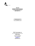
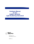
THE FRONT PANEL OF THE DMI SIGNAL CONDITIONER IS DISPLAYED IN FIGURE 1.
PRIOR TO USE THE SYSTEM, THE USER SHOULD MAKE SURE TO HAVE ALL
CONNECTIONS MADE. REFER TO SECTIONS 1.4 AND
1.5 for more information about the front panel connections.
Power connection (section 1.4.1)
RJ-11 Modem connection (Section 1.4.4)
Operating Status LEDs (Section 1.4.2)
Hardware reset button (section 1.4.5)
RS-232 connection (section1.4.3)
ON/OFF button (see automatic
shutdown and anti-shutdown
functionalities at section 1.4.2.1)
Measuring channels and their
fiber optic input connectors
(SECTION
Figure 1: Front panel of DMI
1.2.2
Installing the transducers
1)
Connect the transducer connectors to the input connectors of the DMI (Figure 1)
READ THE HANDLING PRECAUTIONS IN SECTION 1.5.1 BEFORE INSTALLING
AND USING THE TRANSDUCERS FOR THE FIRST TIME.
CAUTION
2
DMI OPERATING MANUAL
1.3
GETTING STARTED
Follow the next instructions to make your first measurements with the DMI conditioner:
Installation of FISOCommanderTM software
1.
The FISOCommanderTM software is easy to use and provides an access to all the signal
conditioner parameters. For more information about the software functionalities, please refer to
the FISOCommander ™ user’s manual.
Here are the steps to install the software using Windows™ operating system:
1. Insert the CD-ROM in the CD-ROM drive.
2. If your computer is handling automatic loading, will prompt you the installation menu
automatically.
3. If not, press “Start” and select “Run”.
4. Type d:\Setup.exe (where d:\ is your CD-ROM drive location) and press “Enter”.
5. Once completed, launch the software.
2.
Save the Gage Factors in the memory of the DMI
The Gage Factor is a 7-digit number located near-by the fiber optic connector of the transducer.
This number provides the DMI signal conditioner with the information related to the transducer
(type, sensitivity, etc). Before using a transducer, its Gage Factor must first be saved into the nonvolatile RAM memory of the conditioner. See section 2.1 for more details.
3.
In FISOCommander™ software, go to the Configuration Transducer tab. In the Transducer:
Gage Factor box, click on «Add» button.
Enter the transducer Gage Factor written on a tag close by its connector. If you are reading
the Gage Factor from the clear plastic box, pay attention to do not confuse the Gage Factor
with the identification number. Once completed, click on «OK».
For easier Gage Factor management, you may enter a mnemonic name, called a Gage Name,
for every Gage Factor stored. This entry is optional. If you do not want to save a Gage Name,
click on «OK». The Gage Factor will then be stored and will remain in the memory buffer even
if it is not assigned to any channel.
Repeat the preceding steps for all the transducers that will be used with your DMI signal
conditioner in order to create the so-called Gage List. This list can contain up to 50 different
Gage Factors. This list is stored in a non-volatile memory so it will not be erased when turning
off the DMI.
If not already done, connect each transducer to the corresponding channel input connectors of
the DMI signal conditioner.
Assign the Gage Factors to the measuring channels
To use a transducer with the DMI, you must first assign its Gage Factor to the corresponding
channel.
3
DMI OPERATING MANUAL
4.
9
Select a DMI channel by moving the mouse pointer into the Transducer: assignment box.
Double click on the desired channel. Make sure that your pointer is located on the channel no.
The selected channel will then appears in bold.
In the Transducer: assignment box, click on the selected channel cell located in the Gage
Name and Gage Factor column. A drop down menu will appear and propose you all the Gage
Factor stored in the Gage List. According to the transducer, select the corresponding
transducer Gage Factor. Note: the default assigned Gage Name and Gage Factor is
FISO1000 (for internal use only).
Repeat the preceding steps for all the transducers that will be used with your DMI conditioner.
Turn off all unused channels by selecting the «OFF» option in the Gage List
Zero adjustment of the transducers
Go directly to the next point if you are using temperature probes only.
The zero adjustment forces the reading of the transducer to be equal to zero immediately after it
is activated. The zero adjustment of the transducer is necessary when using for the first time a
strain gage, force & load, refractive index or a pressure transducer. The zero adjustment function
is automatically disabled in case of a temperature transducer. See section 2.1.3 for more details.
To zero adjust a selected transducer with the FISOCommander™ software, click on the “NULL”
button in the Config Transducer tab.
5.
First acquisition and graphical display
From this point, your DMI signal conditioner is ready to display the data measurements taken with
the fiber optic transducers. For this purpose, we recommend the step by step procedure describe
in the FISOCommander ™ software user’s manual.
4
DMI OPERATING MANUAL
1.4
OPERATING FUNCTIONALITIES
1.4.1
Power supply and external battery operation
The DMI conditioner comes with a wall plug-in or tabletop power
supply/battery charger and with an external battery already connected to the External battery
conditioner (The battery is located inside the NEMA enclosure). The former is
used to power the conditioner and recharge the external battery. The allowed
power supply DC operating voltage is 9 to 15 Volts with a minimum current
capacity of 500 mA.
The external battery is a 6 Volts 4.5 A-hour capacity. The operating
temperature is from 0°C to 40°C. The external battery is mainly used as a
back-up power supply during a shutdown of the external power. It can also be
used as a main power supply in remote location where no external power is
available. In the later case, the DMI autonomy depends of course on the
remaining charge in the battery but it also depends on the operating
conditions of the DMI. The next table provides information about the DMI autonomy during battering
operation for different type of operating conditions.
DMI AUTONOMY DURING BATTERY OPERATION (@ 25°C; BATTERY FULLY CHARGED)
DATA ACQUISITION CONDITIONS
DMI AUTONOMY
Data acquisition of 32 channels with maximum speed of data
measurements (no averaging)
12 hours
Data acquisition of 32 channels with data acquisition rate of 5 data
measurements (no averaging) per hour and per channel
350 hours
Data acquisition of 32 channels with data acquisition rate of 1 data
measurements (no averaging) every 6 hours and per channel
900 hours
1.4.1.1
External battery lifetime: cyclic and standby use
The battery lifetime, that is the maximum number of charge-discharge cycles before the external battery
lose most of its retention capacity and must be replaced, depends on the capacity taken from the external
battery. The following table gives the battery lifetime as a function of the depth of discharge of the battery.
Depth of discharge
Number of cycles
100%
200 to 300
50%
800 to 1000
25%
> 1500
0%
(standby use, always connected to the power supply/battery charger)
(4 to 5 years)
According to the above table, waiting for a complete discharge of the batteries before recharging strongly
reduces the battery lifetime so it is not recommended.
5
DMI OPERATING MANUAL
On the other hand, it is recommended during a long period storage of the DMI to recharge the battery
once every six months in order to maintain its original capacity.The time to recharge the external battery
can vary from 2 to 8 hours depending on the remaining charge of the battery.
1.4.2
Operating status
The red and green LEDs provide information to the user about the operating status of the DMI as
explained in the following table.
9
Red LED
Green LED (ACQ)
ON
OFF
ON
ON
OFF
OFF
Status
•
DMI is ON; Acquisition Mode not activated
ON
•
•
•
•
Acquisition Mode activated
Data measurements going on
Acquisition Mode activated
DMI is in the Sleep State (i.e. waiting for the next data
measurement)
OFF
•
The DMI is off
The DMI can be remotely turned on by sending a string character over the RS-232 serial link or by
calling the DMI internal modem. See next sections.
1.4.2.1
Automatic shutdown
The DMI goes completely off automatically after 15 minutes of inactivity unless it is in Sleep Mode. The
DMI can be remotely turned off at any time with the aid of SYSTEM OFF [WF] remote control command
(see REMOTE CONTROL COMMANDS MANUAL) or with FISOCommander™ software. The automatic
shutdown feature can be disabled and enabled (default state) with the aid of the POWER
MANAGEMENT [GPX] remote control command (See REMOTE CONTROL COMMANDS MANUAL).
Note: this function is irrelevant for NON BATTERY POWERED SYSTEM
1.4.2.2
Anti-Shutdown protection
The DMI is equipped with an anti-shutdown protection that prevent against unattended shutdown that
could happen by pushing the ON/OFF button while a DMI Acquisition Modes (section 4.4.1) is still active.
In this case, the user must hold down the ON/OFF button during at least 5 seconds and then release the
button to turn off the conditioner.
Note: this function is irrelevant for NON BATTERY POWERED SYSTEM
RS-232 Link
The DMI signal conditioner is remotely controlled via a PC computer (or other computer device) with the
aid of the RS-232 serial link or the modem connection (see next section). A set of Remote Control
Commands provides all the functions to operate the conditioner. For more details about the RS-232
remote control of the DMI, consult the REMOTE CONTROL COMMANDS MANUAL. If the DMI is off or in
Sleep State, a string character must be sent to the DMI in order to turn it on.
6
DMI OPERATING MANUAL
9
FISO Technologies suggests using its specially designed remote control software for the DMI
conditioner. This software, called the FISOCommander™, provides an effective and simple tool for
remotely controlling your DMI as well as for downloading and viewing in real-time the data
measurements directly from your PC computer (see section 3.1) using either an RS-232 or modem
connection.
1.4.4
Modem connection
The DMI is equipped with a V.90 standard internal modem that allows the user to remotely control the
DMI through a telephone connection. The internal modem supports communication speed from 300 bps
to 56 kbps.
To use the modem communication, simply connect the DMI to your telephone line using a standard RJ11-to-RJ-11 cable. The DMI internal modem answers automatically immediately after receiving the
second telephone ring signal even if the DMI is off or in Sleep State. Indeed, the modem automatically
turns on the DMI. Once connected via the internal modem, the remote operation of the DMI is the same
as with an RS-232 link. After the remote user hangs up, the internal modem needs approximately one
minute to shut off itself after which, 15 minutes later, the DMI will turn off or goes back in Sleep State.
The FISOCommander™ software can be used with a modem connection. Simply select in
FISOCommander™ software the COM port on which the computer modem is installed and the modem
initialization window will pop-up. Enter the telephone number. For long distance call, it may be necessary
to enter pauses in the dialing sequence of numbers. The easiest way to accomplish this is by using the
standard modem dialing string character "," which causes dialing to pause for each occurrence (ex.:
1,222,111,3333). When ready, click on “OK” to have your computer modem call the DMI internal modem.
Once the communication is established with the DMI, the FISOCommander™ software will bring its
standard user-interface window.
1.4.5
Hardware Reset Button
This button is used to reset the DMI signal conditioner to its original configuration as set at the factory.
9
For a full hardware reset, the power supply must be connected to both a power outlet and your
DMI conditioner. Note that all the Gage Factors of the Gage List and their associated Gage Zero
will be erased from memory.
1.4.6
Memory
The DMI signal conditioner is equipped with a non-volatile RAM type memory where all the settings of the
conditioner (Gage Factors, Gage Zero, etc.) are stored. Each time the DMI conditioner is turned on; it is
reset with the same settings in use just before the last time it was turned off.
The DMI signal conditioner has also a non-volatile memory buffer, which can store close to 50 000 data
measurements. These stored data can be downloaded to a computer via the RS-232 serial or modem
link. See section 4.4.4 for more information.
7
DMI OPERATING MANUAL
1.5
USING THE TRANSDUCERS
1.5.1
Handling of the transducers
READ THE FOLLOWING PRECAUTIONS BEFORE INSTALLING AND USING THE
TRANSDUCERS:
CAUTION
1.5.2
•
Avoid sharp radius turns in the fiber optic cable (radius less than 10 mm)
•
Temperature probe: do not bend the rigid region at the end of the cable. The
sensitive part of the transducer is located inside the rigid region, close to the tip.
•
Strain Gage: do not touch the sensitive part of the transducer. This part must be
kept clean until it is bonded.
•
Avoid tension or twisting of the fiber optic cable
•
Avoid pinch points and “Scissors” when setting in place the transducers
•
Do not pull on fiber optic cable to clear tangles; carefully unwind instead
•
Avoid allowing fiber optic connectors to drop or scrape on hard surfaces
•
Keep the surface of the fiber optic connector clean
Cleaning the transducer connectors (ST type)
For proper use of the fiber optic transducers, the fiber optic connectors must be kept clean and free of
dust at all times. Any dust may obstruct the light transmitted from one connector to the other, and reduce
the signal-to-noise ratio to an unusable level. It is a good practice to always clean the transducer
connector before mating it to the conditioner. Wiping the end with low lint tissue such as Kimwipes or
lens cleaning tissues is a simple and easy way to clean transducer connectors. By keeping your
transducer connectors clean you will also prevent the contamination of the DMI input connectors.
However, we recommend cleaning the DMI input connectors occasionally. Use the specially designed
2.5-mm Mini Foam Swab provided with our cleaning kit for cleaning the input connector of DMI.
1.5.3
Transducer technical notes
Additional information is available on specific fiber optic transducers. Ask your local representative for
FISO Technologies’ specific Fiber optic Transducer Technical Note and Installation Guide such as our
Fiber optic Strain Gage Installation Guide.
8
DMI OPERATING MANUAL
2.0 TRANSDUCER ⇔ CONDITIONER
2.1
TRANSDUCERS
2.1.1
Principle of operation
All the fiber optic transducers made by FISO Technologies are of interferometric type. More specifically,
the sensing element of the transducers is a miniature Fabry-Pérot interferometer. This sensing element is
designed such that a stimulus (i.e. the physical parameter being measured: temperature, pressure,
displacement, etc.…) produces a change in the cavity length (Lcavity) of the Fabry-Pérot interferometer.
Therefore, the cavity length can be seen as the output signal1 of the fiber optic transducer. The
output-stimulus relationship, which establishes the dependence between the output of the transducer,
designated by Lcavity, and the stimulus, designated by M, is characterized by the following linear equation:
L cavity
Where:
= S ⋅M + L
zero
S is the sensitivity of the transducer (in nanometers per physical unit), and Lzero (Gage
Zero) is the output of the transducer when M = 0 (in nanometers).
The accurate factory-calibration of the sensitivity S and of the Gage Zero (Lzero) provides all the necessary
information to calculate, from the measurement of Lcavity, the true value of the stimulus M. The measure of
Lcavity is the basic principle used in all the FISO Technologies’ conditioners. The unit used to measure
Lcavity is the nanometer — this is the internal unit of the conditioner used to represent the output signal of
the transducer, as opposed to the physical units (ºC, Bar, etc…) used to represent the value of the
stimulus.
9
It should be emphasized that the full scale (or the span) of the transducer output Lcavity does not
begin at zero. In other words, FISO Technologies’ fiber optic transducers are made and delivered
with an initial cavity length Lcavity not equal to zero.
2.1.2
The Gage Factor
Before using a transducer with the DMI conditioner, its calibration factor, called the Gage Factor, must be
stored in memory and then assigned to one of the measuring channels of the conditioner. Up to fifty Gage
Factors can be stored in the non-volatile memory of the conditioner, which represent the so-called Gage
List. The Gage Factor allows the conditioner to:
1.
Identify the type of transducers connected
2.
Know the sensitivity S of the transducer as determined by the factory calibration
3.
Know the Gage Zero (Lzero) of the transducer (temperature transducers only) as determined
by the factory calibration.
1
The physical signal measured from the fiber-optic transducer is a light signal. This light signal carries
the information about the cavity length of the Fabry-Pérot interferometer.
9
DMI OPERATING MANUAL
The Gage List contains a default Gage Factor that is the number 0001000 (or 1000). The Gage Name
associated to this factor is FISO. This factor is permanently saved into the conditioner memory and
cannot be erased.
The Gage Factor is printed on a label close to the fiber optic connector of the transducer. It is a 7-digit
number where the first digit indicates the type of transducer, 0 being the default number value and is not
associated with a specific type of transducer. The different numbers used to identify the transducer are
listed next:
0: Is used for non-specific type transducers
08: Is used for refractive index transducers
0X: is reserved for future use
1: Is used for non-compensated strain gage transducers
2: Is used for pressure transducers of type 1
3: Is used for force & load transducers of type 1
4: Is used for temperature transducers of type 1
5: Is used for compensated strain gage transducers
6: Is used for pressure transducers of type 2
7: Is used for force & load transducers of type 2
8: Is used for linear displacement transducers
9: Is used for temperature transducers of type 2
In the case of force & load and pressure transducers, the second digit of the Gage Factor is used to
differentiate, within a transducer lot, the ones with same type and sensitivity. The third digit corresponds
to a multiplying factor while the last four digits correspond to the sensitivity S of the transducer divided by
the multiplying factor. It is the same for the strain gage and the linear displacement transducer except that
the last five digits correspond to the sensitivity S. In the case of the temperature transducers, the last six
digits correspond to the sensitivity S and the Gage Zero Lzero. See section 2.1.3 for more information.
2.1.2.1
To add (or remove) a Gage Factor to the Gage List
To add or remove a transducer Gage Factor, use the GAGE ADD remote control command described in
REMOTE CONTROL COMMANDS MANUAL or go in the Config Transducer tab of the
FISOCommander™ software. You may enter with the Gage Factor a Gage Name to facilitate the
identification of the corresponding transducer. The Gage Name can be composed of up to five
alphanumeric characters: {0-9} {A-Z} {: ;}. If you do not want to assign yourself a Gage Name just enter
the Gage Factor. The conditioner will then assign a default Gage Name.
2.1.2.2
To assign the Gage Factors to the measuring channels
To use a transducer with the DMI, you must first assign its Gage Factor to the corresponding channel,
that is the one to which the transducer is connected.
Use the GAGE SELECT [GA“Gage Factor”] or [GA“Gage Name”] remote control command as described
in REMOTE CONTROL COMMANDS MANUAL or go in the Config Transducer tab of the
FISOCommander™. Your selection must correspond to the Gage Factor of the transducer actually
connected to the measuring channel. Repeat the preceding steps for all the measuring channels that will
be used. Select the “OFF” option to deactivate the unused channels ([GA0] remote control command).
10
DMI OPERATING MANUAL
9
It is strongly recommended to deactivate all unused channels (“OFF” option), otherwise the
conditioner automatically assign the default Gage Factor “1000” and its corresponding Gage
Name “FISO”.
9
Note that when the Gage Factor 1000 (or 0001000) is assigned, the conditioner gives the actual
value of the output signal of the transducer that is the value of its cavity length Lcavity. This value is
given in Internal Units, i.e. in nm. (See section 2.1.1)
2.1.3
Calibration
As explained in section 2.1.1, FISO Technologies’ fiber optic transducers are characterized by a linear
relationship between the stimulus M, and the output signal produced by the transducer, that is the cavity
length (Lcavity) of the Fabry-Pérot interferometer. The factory-calibration of the transducer is made by
measuring, for a set of accurately-known values of M, the corresponding values of Lcavity. These
measurements establish the calibration curve of the transducer by providing the value of the sensitivity S
and the value of the Gage Zero (Lzero). Once these two parameters are known, it is easy to assign to each
measured value of Lcavity the corresponding value of the stimulus M. The conditioner uses the following
equation to calculate and output the values of M as a function of the output values Lcavity of the transducer:
M ( L cavity ) =
(L cavity
− L zero
)
S
(2)
The factory-calibration varies depending of the type of the transducers as explained next.
Temperature Transducer: the Gage Factor of the temperature transducer provides both the sensitivity S
and the Gage Zero (Lzero). Therefore, the temperature transducer is fully calibrated and ready to use.
Strain Gage Transducer: the Gage Factor of this transducer provides only the sensitivity S. The Gage
Zero is not included at the factory because it would have no physical meaning at this point. Clearly, the
Gage Zero of the strain gage transducer has, in general, a real signification only when it is installed, that
is when it is bonded to the structure to be studied. At first, the DMI conditioner fixes the default value of
the Gage Zero to zero (Lzero = 0 nm). However, the zero and offset adjustment functions of the conditioner
allow the user to automatically define at any time a new value of the Gage Zero — for example, after
bonding the transducer (See sections 2.1.3.1 and 2.1.3.2).
Pressure Transducer: the Gage Factor of this transducer provides only the sensitivity S. The Gage Zero
is not included at the factory because in general these transducers are of gage type (i.e. pressure
measured relative to the ambient or atmospheric pressure). At first, the DMI conditioner fixes the default
value of the Gage Zero to zero (Lzero = 0 nm). However, the zero and offset adjustment functions of the
conditioner allow the user to automatically define at any time a new value of the Gage Zero (See sections
2.1.3.1 and 2.1.3.2). Note that in the case of absolute pressure type of transducer, FISO Technologies
provides separately a calibrated value of Lzero. The offset function in Internal Unit allows the user to enter
this value and assign it to the Gage Factor of that transducer. (See section 2.1.3.2).
Force & Load Transducer: the Gage Factor of this transducer provides only the sensitivity S. At first, the
DMI conditioner fixes the default value of the Gage Zero to zero (Lzero = 0 nm). However, the zero and
offset adjustment functions of the conditioner allow the user to automatically define at any time a new
value of the Gage Zero (See sections 2.1.3.1 and 2.1.3.2).
11
DMI OPERATING MANUAL
Displacement Transducer: the Gage Factor of this transducer provides only the sensitivity S. At first,
the DMI conditioner fixes the default value of the Gage Zero such as to obtain 0 mm (or 0 inch) at the
center position of the transducer. However, the zero and offset adjustment functions of the conditioner
allow the user to automatically define at any time a new value of the Gage Zero (See sections 2.1.3.1 and
2.1.3.2).
Refractive index gauge : the Gage Factor of this transducer provides only the optical cavity length. After
a simple zeroing, which corresponds to the physical cavity length, then the gage is ready to use. (See
APPENDIX A)
2.1.3.1
Zero adjustment of the transducer
The zero adjustment forces the data measurements of a given transducer to be equal to zero immediately
after it is activated. This is achieved with the aid of the ZERO PHYSICAL remote control command
(REMOTE CONTROL COMMANDS MANUAL) or with the FISOCommander™ software (<<NULL>>
button in the Config Transducer tab). The operating principle of this function is described next:
1.
Immediately after receiving the ZERO PHYSICAL [ZO0] remote control command or after
pressing the <<NULL>> button in the Config Transducer tab of the FISOCommander™
software, the conditioner performs a measurement of Lcavity of the transducer.
2.
Thereafter, the conditioner assigns this value of Lcavity to Lzero; that is Lcavity → Lzero.
3.
At this point, one could see that the values of the data measurement taken right after the
zero adjustment are equal or close to zero. Indeed, if the value of the stimulus has not
changed (or very little) since the zero adjustment, its calculated value M from equation 2
must be equal or close to zero knowing that Lcavity ≅ Lzero
The zero adjustment function allows the user to specify or select the physical conditions at which the
calculated value of the stimuli M must equal zero. It should be emphasized at this point that: 1) FISO
Technologies’ transducers are made and delivered with an initial cavity length Lcavity not equal to zero, 2)
Except for temperature and displacement transducers, the default value of the Gage Zero of the
transducers is set to zero (Lzero = 0 nm). Consequently, when using for the first time the strain gage, force
& load, or pressure transducer, the conditioner will output a non-zero value of M even though there is no
physical or real stimulus applied on the transducer (see equation 2). This situation will remain until the
user redefines a new value of Lzero.
In the case of the strain gage transducer, the zero adjustment is usually done after bonding the
transducer to the structure. For pressure transducer of gage type, the zero adjustment is done at
atmospheric pressure or in vacuum (See next section for absolute pressure). The technical notes
published by FISO Technologies for pressure and strain gage transducers provide more information on
this subject.
The principal characteristics of the zero adjustment that should be reminded are:
9
The measurement of the cavity length Lcavity, performed during the zero adjustment function, is
done the same way as the data measurements (see section 4.0). Thus, parameters such as the
Averaging Time will affect the results. Obviously, the value of the stimulus must be as stable as
possible during the measurement of Lcavity in order to make an accurate zero adjustment.
12
DMI OPERATING MANUAL
9
A new value of Lzero is redefined each time the zero adjustment function is activated. The new value
replaces the preceding one and becomes the current value of Lzero. To look for the current value of
Lzero, use the ZERO DOWNLOAD (REMOTE CONTROL COMMANDS MANUAL) remote control
command or go in the Config Transducer tab of the FISOCommander™ software.
9
Despite the fact that the zero adjustment is only active with the selected measuring channel, this
function is transducer-specific: the resulting value of Lzero will be associated to the Gage Factor
currently assigned to the selected channel. That means the Gage Zero will always stick to its
associated Gage Factor even though the later is re-assigned to another channel. Note that
removing a Gage Factor from the Gage List will erase its associated Gage Zero as well.
9
The zero adjustment function is automatically disabled in the case of a temperature transducer.
9
The zero adjustment should be performed when the strain gage, force & load, refractive index or
gage pressure transducers are being used for the first time (for absolute pressure, see section
2.1.3.2).
9
It is recommended to take note of the current value of Lzero when doing a zero adjustment.
Knowing that it is possible to re-enter an arbitrary value of Lzero, it could be useful in the case the
conditioner is reset or its memory content is lost. See the ZERO DOWNLOAD remote control
command in REMOTE CONTROL COMMANDS MANUAL.
Offset adjustment of the transducer
2.1.3.2
The offset adjustment of the transducer, done with the aid of the ZERO PHYSICAL or ZERO INTERNAL
remote control command, or with the FISOCommander™ software (in the Config Transducer tab),
forces the data measurements of a given transducer to be equal to an arbitrary value immediately after it
is activated. The operating principle of this function differs according to the selected unit.
A.
Offset with physical units
The offset adjustment function in physical units is the same as the zero adjustment except that the
entered value is different from zero. The entered value will thus correspond to the data measurements
displayed right after the function is activated. Using the ZERO PHYSICAL [ZO“Offset value”] remote
control command or with FISOCommander™ software (<<PHYSICAL>> button in the Config
Transducer tab), the offset value is entered in the units that correspond to the transducer actually
connected to the selected channel (For example, the value is entered in psi or Bar in the case of a
pressure transducer).
1.
Immediately after receiving the ZERO PHYSICAL [ZO“Offset value”] remote control
command or after confirming your offset entry in the Physical dialog box of the
FISOCommander™ software, the conditioner performs a measurement of Lcavity of the
transducer.
2.
Thereafter, the conditioner recalculates a new value of Lzero from the measured value of Lcavity
and the offset value just entered, the later being assigned to M in equation 2. In other words,
the conditioner calculates a Lzero value that gives a value of M equal to the offset value:
Lzero = Lcavity − (S × offset value ) .
13
DMI OPERATING MANUAL
3.
At this point, one could see that the values of the data measurement taken right after the
offset adjustment are equal or close to the offset value. Indeed, if the value of the stimulus
has not changed (or very little) since the offset adjustment, its calculated value M from
equation 2 must be equal or close to the offset value knowing that
Lcavity ≅ Lzero + (S × offset value )
B.
Offset with Internal Unit
As opposed to the zero and physical units offset adjustment functions, there is no measurement of Lcavity
since the entered value is directly assigned to Lzero without any other calculation. Using the
ZERO INTERNAL [ZP“Offset value”] remote control command or with FISOCommander™ software
(<<INTERNAL>> button in the Config Transducer tab), the offset value is entered in Internal Unit that is
in nanometers.
1.
Immediately after receiving the ZERO INTERNAL [ZP“Offset value”] remote control
command or after confirming your offset entry in the Internal dialog box of the
FISOCommander™ software, the conditioner assigns the entry to Lzero and it becomes the
new current value.
2.
At this point, the new current value of Lzero will affect the values of the data measurement
according to equation 2.
The offset adjustment with Internal Unit is generally used to re-enter a given value of Lzero, for example,
when the current value of Lzero is accidentally erased from the conditioner memory or when the transducer
is to be used with another conditioner. This function can also be used to enter a calibrated value of Lzero,
as for absolute pressure transducers.
The principal characteristics of the offset adjustment that should be reminded are:
9
The measurement of the cavity length Lcavity, performed during the offset adjustment in physical
units, is done the same way as the data measurements (see section 4.0). Thus, parameters such
as the Averaging Time will affect the results. Obviously, the value of the stimulus must be as
stable as possible during the measurement of Lcavity in order to make an accurate offset
adjustment.
9
A new value of Lzero is redefined each time the offset adjustment function is activated. The new
value replaces the preceding one and becomes the current value of Lzero. To look for the current
value of Lzero, use the ZERO DOWNLOAD (SEE REMOTE CONTROL COMMANDS MANUAL) remote
control command or go in the Config Transducer tab of the FISOCommander™ software.
9
Despite the fact that the offset adjustment is only active with the selected measuring channel, this
function is transducer-specific: the resulting value of Lzero will be associated to the Gage Factor
currently assigned to the selected channel. That means the Gage Zero will always stick to its
associated Gage Factor even though the later is re-assigned to another channel. Note that
removing a Gage Factor from the Gage List will erase its associated Gage Zero as well.
9
The offset adjustment function is automatically disabled in the case of a temperature transducer.
9
The offset adjustment function with Internal Unit can be useful to enter a calibrated value of Lzero.
This is particularly the case with absolute pressure transducers.
14
DMI OPERATING MANUAL
3.0 CONDITIONER REMOTE CONTROL
3.1
FISOCOMMANDER™ SOFTWARE
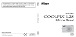
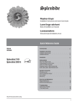
FISO Technologies offers specially designed remote control software for the DMI conditioner. This
software, called the FISOCommander™, provides an effective and simple tool for remotely controlling
your DMI as well as for downloading and viewing in real-time the data measurements directly from your
PC computer. The figures below show few of the many features offered by this software.
FISOCommander™ is offered in a free demonstration version (Lite version) or is sold in Full version. For
more information about the FISOCommander™, please refer to the software user’s manual.
Transducer Assignment dialog box
Transducer Configuration Menu
Direct Data Acquisition window
(Line Graph)
Direct Data Acquisition window
(Bar Graph with alarms)
15
DMI OPERATING MANUAL
4.0 THE DATA MEASUREMENT & ACQUISITION
4.1
DATA SAMPLING AND AVERAGING
The signal conditioning of FISO Technologies’ fiber optic transducers consists of the following steps.
1.
The DMI conditioner samples the transducer signal, connected to one of the measuring
channels, at a fix Sampling Rate of 20 Hz. Consequently, the conditioning process of the
sampled signal from the transducer generates one data reading every 1/20 or 0.05
second.
2.
The data readings generated at this 20 Hz Sampling Rate are averaged during an
adjustable period of time as set by the user with the Averaging Time parameter.
3.
The average value of the data readings, referred as the data measurement, is thereafter
available for memory storage or outputting to the RS-232 (or modem) port depending on
the Acquisition Mode selected.
4.
During data acquisition (see section 4.4), the three preceding steps will be repeated at
every interval of time given by the Acquisition Rate if manual scan mode is selected. If the
automatic scan mode is selected, the conditioner will first switch to the next channel and
repeat the preceding steps. The complete scan of the channels will be repeated at every
interval of time given by the Acquisition Rate. See section 4.4, the timing diagrams of
Figure 2 and Figure 3 for more information.
The Averaging Time is set with the ACQUISITION AVERAGE remote control command or in the Config
Conditioner tab of FISOCommander™ software. The minimum value of the Averaging Time is 0.05
second where in this case there is no averaging since the data measurement is obtained from one data
reading. To calculate the number of data readings that is used to produce one data measurement, simply
multiply the Averaging Time by 20 Hz.
The Acquisition Rate is set with the ACQUISITION RATE remote control command or in the Config
Conditioner tab of FISOCommander™ software. The meaning and permitted values of Acquisition Rate
depends of the scanning mode; see sections 4.4.2, 4.4.3, Figure 2 and Figure 3.
9
The default value of Averaging Time for the DMI Long Range version is factory preset at 1.0
second and should not be decreased when using transducer with long length of fiber optic cable.
Whenever it is possible, it is recommended to set the Averaging Time to a value larger or at least
equal to 1.0 second.
4.2
AUTOMATIC SCAN
The measuring channels of the DMI conditioner can be scanned in two ways: automatic and manual
scan. The scanning method is selected by mean of the Acquisition Modes. See section 4.4.1
When set to automatic scan mode, the data measurements are sequentially taken on each of the
activated DMI channels. The conditioner switches from one active channel to the next active one in
ascending order (ex: channel no 1→2→3→4→….). This scanning cycle is continuously repeated:
→1→2→3→4→…→1→2→….
16
DMI OPERATING MANUAL
The Scanning Time is defined as the time required for switching to a channel a get a data measurement
of that channel. This time varies with the Averaging Time and with a stabilization time fixed at 0.1 second.
Note: The stabilization time is fixed at 0.4 seconds for a DMI Long Range version.
Scanning Time = Averaging Time + 0.1 second
(seconds/channel)
(3)
The smallest and default value of the Scanning Time is 0.15 second/channel, that is when the Averaging
Time is set to its minimum value of 0.05 second. It should be emphasized that the conditioner skips the
deactivated channels (i.e. channels turned OFF). Consequently, it is recommended to set the non-used
channels to OFF to minimize the time required for a complete scan of the channels.
4.3
MANUAL SCAN
When set to manual scan mode, the data measurements are taken with one measuring channel. This
mode gives the fastest means of measurement that is up to 20 data measurements per second.
9
In manual scan, the amount of time between two consecutive data measurement is equal to the
Averaging Time since there is no stabilization time.
4.4
DATA ACQUISITION
4.4.1
Acquisition Modes
The DMI conditioner offers different methods of making data acquisition through a selection of several
Acquisition Modes. These modes are divided into two classes, that is the direct data acquisition and the
delayed data acquisition, the later is subdivided into two other classes: data acquisition at set duration
and programmable data acquisition. The direct data acquisition means that each data measurement is
immediately sent to the RS-232 (or modem) link of the conditioner without storage in the buffer memory.
On the other hand, the data measurements taken during the delayed data acquisition (set duration or
programmable) are stored into memory and must be downloaded with the DATA DOWNLOAD remote
control command or with the aid of FISOCommander™ software (Delayed-Acquisition tab).
Each Acquisition Mode offers other options such as data acquisition in automatic or manual scan of the
measuring channels. The DMI switches immediately to manual or automatic scan depending on the
Acquisition Mode that is selected.
The Acquisition Modes are selected with the ACQUISITION MODE remote control command. See Table
2 and the next sections for additional explanation on each Acquisition Mode. When using the
FISOCommander™ software, the selection of the proper Acquisition Mode is done automatically by the
software.
4.4.2
Data Acquisition in Manual Scan
When the conditioner is set to manual scan, the data acquisition consists of storing (or directly outputting
to RS-232 or modem link) one data measurement at every interval of time given by the Acquisition Rate
parameter. See Figure 2 for the timing diagram of the data acquisition when in manual scan. It should be
noted that the data measurements are taken according to the Averaging Time initially set by the user
(section 4.1). That is the averaging process is done on a 20 Hz sampling rate basis which means the DMI
conditioner calculates an average value of the data readings collected at every 0.05 second and during
the period of time set with the Averaging Time parameter.
17
DMI OPERATING MANUAL
The averaging process is always started at the beginning of the period as set with the Acquisition Rate
parameters. For example, if the Averaging Time is set to 40 seconds and the Acquisition Rate is set to
two minutes, the DMI conditioner will store (or output) the average value of the first 800 data readings (20
Hz X 40 s) of the 2400 (20 Hz X 120s) available data readings (rounded to the closest integer). It should
be noted that the Acquisition Rate parameter could not be smaller than the Averaging Time. If the user
tries to set the Averaging Time larger than the Acquisition Rate, the later will be automatically reset (at the
start of the acquisition) to a value equal to the Averaging Time.
4.4.3
Data Acquisition in Automatic Scan
When the conditioner is set to automatic scan, the data acquisition is performed by storing (or by directly
outputting to the RS-232 or modem link), at every interval of time given by the Acquisition Rate, the data
measurements taken during one scanning cycle. See Figure 3 for the timing diagram of the data
acquisition when in automatic scan. It should be noted that the data measurements are taken according
to the Averaging Time initially set by the user (section 4.1). That is the averaging process is done on a
20 Hz sampling rate basis which means the DMI conditioner calculates an average value of the data
readings collected at every 0.05 second and during the period of time set with the Averaging Time
parameter. The averaging process is always started at the beginning of the period as set with the
Acquisition Rate parameters. For example, a DMI-32 with its thirty-two channel activated has the
Averaging Time set to 1.90 second and the Acquisition Rate set to 120 seconds. The conditioner starts
the acquisition on channel no 1 with the averaging of 38 data readings (20 Hz x 1.90 s). The resulting
data measurement is then stored in memory or outputted to the RS-232 link. Thereafter, the conditioner
switches to channel no 2 and performs the same steps. These steps are repeated for each channel until
the end of the scanning cycle (total duration of 64 seconds, including stabilization period of 0.1 second
per channel), that is at channel no 32. This cycling process is repeated at every interval of time given by
the Acquisition Rate that is 56 seconds after the last data measurement taken on the channel no 32.
The lowest possible value of the Acquisition Rate is equal to the Scanning Time multiply by the number of
activated channels that is the time of a scanning cycle. If the user tries to enter a lower value, the
Acquisition Rate will be automatically reset (at the start of the Acquisition Session) to this limiting value.
18
DMI OPERATING MANUAL
TABLE 2: ACQUISITION MODES (See ACQUISITION MODE command in REMOTE CONTROL COMMANDS MANUAL)
OTHER SPECIFIC
SCAN
ACTIVATION /
START
STOP
PARAMETERS AND
NAME
COMMAND
DATA STORAGE
MODE *
DEACTIVATION
PARAMETER
PARAMETER
FEATURES
NORMAL
[TM0]
Manual
Yes
[TS1]/[TS0] commands
SINGLE
[TM1]
Manual
Yes
[TS1]/[TS0] commands
RS-232
[TM2]
Manual
No
(Direct acquisition)
[TS1]/[TS0] commands
None
(Starts immediately
after activation)
None
(Starts immediately
after activation)
Acquisition Duration
or deactivation
Averaging Time
Acquisition Rate
None (single data
measurement)
Averaging Time
None
(Starts immediately
after activation)
Acquisition Duration
or deactivation
Averaging Time
Acquisition Rate
”READY” string
Ending Time
(repeated every
day) or deactivation
See PROGRAM #
commands in REMOTE
CONTROL COMMANDS
MANUAL
Acquisition Duration
or deactivation
Averaging Time
Acquisition Rate
”READY” string
Acquisition Duration
or deactivation
Averaging Time
Acquisition Rate
PROGRAM/CONT
[TM3]
Automatic
Yes
[TS1]/[TS0] commands
Starting Time
(repeated every day)
READY
[TM4]
Manual
Yes
[TS1]/[TS0] commands
None
(Starts immediately
after activation)
[TM5]
SCAN
[TM6]
RESERVED FOR INTERNAL USE
Automatic
Yes
[TM7]
[TS1]/[TS0] commands
None
(Starts immediately
after activation)
RESERVED FOR INTERNAL USE
RS-232/SCAN
[TM8]
Automatic
No
(Direct acquisition)
[TS1]/[TS0] commands
None
(Starts immediately
after activation)
None (continuous),
deactivation only
Averaging Time
Acquisition Rate
PROGRAM/DATE
[TM9]
Automatic
Yes
[TS1]/[TS0] commands
Starting Date and
Starting Time
Ending Date and
Ending Time or
deactivation
See PROGRAM #
commands in REMOTE
CONTROL COMMANDS
MANUAL
* Note: the DMI switches immediately to manual or automatic scan according to the Acquisition Mode selected
19
DMI OPERATING MANUAL
Figure 2: Timing Diagram of Data Acquisition in Manual Scan Mode
(Example given with channel no 1 selected)
The Conditioner goes automatically
into Sleep State if the remaining time
before the next measurement is larger
than 12 seconds
Averaging Time (adjustable; ≥ 0.05 s)
Acquisition Rate (adjustable; ≥ Averaging Time)
1
1
3)
2)
1)
Time Scale
20
Channel no 1 selected
1
Data acquisition repeated at every interval of time given by the Acquisition Rate
One data measurement produced by the averaging of the data readings collected during the Averaging Time (This example shows the averaging
of 3 data readings) and stored in the memory (if using delayed acquisition) or sent to the RS-232 (or modem) link (if using direct acquisition)
One data reading of the transducer collected every 0.05 s
DMI OPERATING MANUAL
Figure 3: Timing Diagram of Data Acquisition in Automatic Scan Mode
(Example given with channels no 1 to 4 activated)
Acquisition Rate (adjustable; ≥ Scanning Cycle)
Scanning Cycle ( = Scanning Time x Number of activated channels)
The Conditioner goes
automatically into Sleep State
if the remaining time before
the next measurement is
larger than 12 seconds
Scanning Time ( = Averaging Time + 0.1 second)
Stabilisation Period ( = 0.1s)
Averaging Time (adjustable; ≥ 0.05 s)
Sampling Rate ( = 0.05 s)
¼
1
¼
¼
2
¼
3
¼
4
1)
2)
3)
4)
5)
Time Scale
21
1
¼
2
¼
3
¼
4
One data reading of the transducer collected every 0.05 s
One data measurement produced by the averaging of the data readings collected during
the Averaging Time (this example shows the averaging of 3 data readings)
One data measurement per channel stored in the memory (if using delayed acquisition) or sent to the RS232 (or modem) link (if using direct acquisition) at every interval of time given by the Scanning Time
Data measurements completed on all the activated channels in a period of time given by the Scanning Cycle
Data acquisition (Scanning Cycle) repeated at every interval of time given by the Acquisition Rate
Measuring
¼
Channels
1
2
¼
DMI OPERATING MANUAL
4.4.4
Delayed Data Acquisition
The DMI signal conditioner has an integrated data logger (memory buffer) for real time storage of the data
measurements. The process of making a delayed data acquisition and data storage in memory is called
an Acquisition Session. The term “delayed” means that the data measurements will be available as soon
as the acquisition session has begun logging.
4.4.4.1
Data Acquisition at set duration
Use the ACQUISITION MODE command to select the appropriate Acquisition Mode among the ones that
have a set duration (see Stop parameter in Table 2). The duration of the Acquisition Session is adjusted
with the Acquisition Duration parameter. Use the ACQUISITION DURATION remote control command to
set the value of this parameter or go in the Config Conditioner tab of FISOCommander™ software.
To activate the Acquisition Session, send the TRIGGER [TS1] command (Note: The data acquisition at
set duration can be done with the FISOCommander™ software as well). To stop the Acquisition Session,
send the TRIGGER [TS0] command, otherwise Acquisition Session terminates when the elapsed time
since the beginning of the session becomes equal to the Acquisition Duration. Note that the memory
buffer store close to 50 000 data measurements — that may limit the maximum value of the Acquisition
Duration. To use the full capacity of the memory, simply set the Acquisition Duration to 00h00m00.00. In
that case, the Acquisition Session will terminate when the memory buffer is full.
The other time-based parameters of the Acquisition Session are the Averaging Time and the Acquisition
Rate. These acquisition-setting parameters can be adjusted with the remote control commands
ACQUISITION AVERAGE and ACQUISITION RATE respectively. See preceding sections.
4.4.4.2
Programmable Data Acquisition
Up to five different Acquisition Sessions can be programmed and each one of them can be activated at a
specific date and time. These programmed Acquisition Sessions are called the Acquisition Programs. To
create an Acquisition Program, the user must download into the conditioner memory (from a PC
computer) the program parameters: starting and ending date & time, Averaging Time, etc. Each
Acquisition Program is numbered from one to five. This programmed mode of acquisition can be activated
with the TRIGGER [TS1] remote control command or with FISOCommander™ software in the DelayedAcquisition tab. When activated, the DMI conditioner will start the Acquisition Programs in chronological
order as given by their respective Starting Date & Time.
The user creates its own Acquisition Programs via the different PROGRAM# remote control commands
(see PROGRAM#(command) in REMOTE CONTROL COMMANDS MANUAL) or with the aid of
FISOCommander™ software (Delayed-Acquisition tab). An Acquisition Program consists of the
following parameters:
1.
2.
3.
4.
5.
6.
22
Starting Time (0 to 23h59m59.9)
Starting Date (yyyyMMdd)
Acquisition Rate (0.05 to 09h59m.95)
Averaging Time (0.05 to 54m36.75)
Ending time (0.05 to 23h59m59.95)
Ending Date (yyyyMMdd)
See PROGRAM# STARTTIME command
See PROGRAM# STARTDATE command
See PROGRAM# RATE command
See PROGRAM# AVERAGE command
See PROGRAM# ENDTIME command
See PROGRAM# ENDDATE command
DMI OPERATING MANUAL
An Acquisition Program is said enabled when its Acquisition Rate value is different from zero. One can
disabled a given Acquisition Program by setting its Acquisition Rate to zero. To activate a set of enabled
Acquisition Programs, first use the ACQUISITION MODE [TM3] or [TM9] command to select the
appropriate programmable Acquisition Mode. Then send the TRIGGER [TS1] command. These steps can
be done as well in the Delayed-Acquisition tab of FISOCommander™ software. The DMI will run the set
of activated Acquisition Programs in chronological order as given by the Starting Time and Starting Date
(TM9 mode only) of each program. In case of time and date overlap between different Acquisition
Programs, the Starting time (or date) of a given Acquisition Program has priority over the Ending time (or
date) of the preceding Acquisition Program. It means that the DMI may jump to the next Acquisition
Program while the actual Acquisition Program is not terminated yet.
Note: in TM3 mode, the Acquisition Programs are run again every 24 hours (the date is ignored) until the
next TRIGGER command is sent to the DMI.
The following example shows
TM9 Acquisition Program:
∨ ∨
[SF 2 20001124]
∨ ∨
[SA 2 013000]
∨ ∨
[SG 2 20001126]
∨ ∨
[SB 2 023000]
∨ ∨
[SC 2 000100.00]
∨ ∨
[SD 2 0010.00]
a list of the Remote Control Commands to send to the DMI for creating a
Set the Starting Date of Acquisition Program # 2 to 2000-11-24
Set the Starting time of Acquisition Program # 2 to 01h30m00s
Set the Ending Date of Acquisition Program # 2 to 2000-11-26
Set the Ending time of Acquisition Program #2 to 02h30m00s
Set the Acquisition Rate of Acquisition Program #2 to 1 minute
Set the Averaging Time of Acquisition Program #2 to 10 seconds
The listing of a given Acquisition Program # can be viewed with the PROGRAM# SHOW remote control
command. Refer to the REMOTE CONTROL COMMANDS MANUAL for more information.
4.4.4.3
Data Logging and Downloading
Each time an Acquisition Session is started, a new data file is created and opened in the memory of the
DMI conditioner. The content of this file includes the data measurements and other useful information on
the acquisition. The file (ASCII characters text file) is called the Acquisition Series and can be easily
downloaded to a computer with the aid of the DATA DOWNLOAD [DD] command or using the
FISOCommander™ software. The Acquisition Series file includes a four-line header and the data
measurements taken during the duration of the Acquisition Session. First line of the header contains the
Acquisition Series number, the value of the Acquisition Rate, the value of the Averaging Time, the date of
the Acquisition Session, the time at which the Acquisition Session was started, and the system of Units.
The Acquisition Series number indicates the chronological order of the Acquisition Session, i.e. 1 is the
first Acquisition Session, 2 is the second Acquisition Session, etc. The second line of the header indicates
the channel numbers from which the data measurements are taken. Each channel number defines a row
under which is written the Gage Name (third line of the header), followed by the Gage Factor (fourth line
of the header.) and then next by the data measurements, each line of data corresponding to a scanning
cycle (if in automatic scan mode). Use the LIST TAG [LT] command or FISOCommander™ software to
get a listing of all the Acquisition Series stored in the memory buffer without the data measurements.
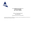
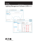
FIGURE 4 shows an example of the content of an Acquisition Series file.
23
DMI OPERATING MANUAL
FIGURE 4:
CONTENT OF THE ACQUISITION SERIES FILE
(This example shows the acquisition made on channel 1 to 4)
Acquisition
Session no 3
Acquisition Rate
= 4.0 second
Averaging Time
= 1.4 second
Starting date of the
Acquisition Session
Starting time of the
Acquisition Session
3
\t 4.0
\t 1.4
\t 2000-10-25
\t
1
\t 2
\t 3
\t 4
\n\r
Temp1
\t Temp2
\t Press1
\t Press2
\n\r
\t 6024195
\t 6025592
\n\r
4755823 \t 4852321
152.1
\t 148.9
\t 54.96
\t 55.10
\n\r
152.3
\t 148.8
\t 54.96
\t 55.14
\n\r
152.5
\t 148.6
\t 54.92
\t 55.10
\n\r
152.6
\t 148.8
\t 54.94
\t 55.16
\n\r
152.8
\t 148.9
\t 54.94
\t 55.10
\n\r
153.9
\t 148.7
\t 54.92
\t 55.14
\n\r
154.0
\t 148.5
\t 54.94
\t 55.12
\n\r
Data on the same line are separated with a tab character
4.4.4.4
System of Units
(M= SI units)
17h35 \t M
\n\r
Channel number
Gage Name
Gage Factor
Data measurements
Each line ends with Line Feed and Carriage Return characters
Deleting the Memory Buffer
We recommend clearing the contents of the memory buffer once the data measurements have been
downloaded. This ensures that the full capacity of the memory buffer is available for the next Acquisition
Sessions. To delete the contents of the memory buffer, use the CLEAR BUFFER [CB] remote control
command or go in the Delayed-Acquisition tab of the FISOCommander™ software.
4.4.5
Direct Data Acquisition
If a direct data acquisition mode is selected, each data measurement is immediately sent to the RS-232
or modem link of the conditioner without storage in the memory. Use the ACQUISITION MODE [TM2] or
[TM8] remote control command to select the appropriate direct Acquisition Mode and then send the
TRIGGER [TS1] command to activate the acquisition. When the direct data acquisition is set in manual
scan (RS-232 [TM2] mode), a space character separates each data measurement (taken on a single
channel) that is sent to the RS-232 output. The string READY is sent at the end of the last data
measurement. No information is given on the acquisition parameters, the Gage Factor, the unit of the
measure, etc. The next figure shows the output of seven data measurements taken on a single channel:
24
DMI OPERATING MANUAL
FIGURE 5:
DATA MEASUREMENTS OUTPUT FOR DIRECT DATA ACQUISITION WITH
RS-232 [TM2] MODE
Space character
The string “READY” is sent at the end of
the Acquisition Session
∨
∨
∨
∨
∨
∨
∨
22.5 22.5 22.5 22.4 22.6 22.5 22.5 READY
Data measurement
When the direct data acquisition is set in automatic scan (RS-232/SCAN [TM8] mode), each data
measurement collected on the different channels are placed on separate lines. The line begins with the
channel number (ex.: CH01) followed by a tab character, then the data measurement and it terminates
with a line feed (\n) and carriage return (\r) character. No information is given on the acquisition
parameters, the Gage Factor, the unit of the measure, etc. The example below shows the output of data
measurements when in automatic scan mode:
FIGURE 6:
DATA MEASUREMENTS OUTPUT FOR DIRECT DATA ACQUISITION
WITH RS-232/SCAN [TM8] MODE (example shows channels 1 to 4)
CH01\t22.5\n\r
CH02\t22.4\n\r
Channel number
CH03\t22.4\n\r
CH04\t22.3\n\r
Data measurement
CH01\t22.2\n\r
CH02\t22.1\n\r
CH03\t22.4\n\r
Tab character CH04\t22.3\n\r
CH01\t22.3\n\r
Line feed and carriage return
CH02\t22.1\n\r
characters
CH03\t22.5\n\r
The duration of the direct data acquisition (set with the Acquisition Duration parameter) can be adjusted
only in the RS-232 [TM2] mode. The RS-232/SCAN [TM8] mode is continuously running and stops with
the TRIGGER [TS0] remote control command. The other time-based parameters of the direct data
acquisition are the Averaging Time and the Acquisition Rate. These acquisition-setting parameters can be
adjusted with the remote control commands ACQUISITION AVERAGE and ACQUISITION RATE
respectively.
The direct data acquisition can be performed with the aid of FISOCommander™ software as well. See
Direct-Acquisition tabs in the software.
4.4.6
Sleep State
Note : the sleep state is irrelevant for NON BATTERY POWERED SYSTEM
When it goes in Sleep State, the DMI signal conditioner turns off most of its hardware so to reduce its
power consumption. By doing so, the system will preserve the battery power. If the user wants to
communicate with the DMI while in Sleep State, a wake up signal must be send first to the DMI.
25
DMI OPERATING MANUAL
This can be done by three different ways: pushing once the ON/OFF button, sending a string character
via the RS-232 link, or by way of modem communication, i.e. calling the DMI internal modem (section
1.4.4).
The red LED off with the green LED on the front panel indicates that the DMI is in the Sleep State. This
state means that one of the DMI Acquisition Modes is activated and still active (for example an Acquisition
Program is to be started at a set date and time), but no data measurements is being taken nor is being
planned for at least the next 12 seconds.
Low power state ( using system without battery)
When it goes in low power state, the DMI-rackmount signal conditioner keeps the minimum hardware ON
for remote communication and turns OFF all other non-necessary hardware (ex. Lamps). The user has
still access to the Remote Control Commands such as, for example, downloading data or programming
the conditioner. This state means that one of the DMI-rackmount Acquisition Modes is activated and still
active (for example an Acquisition Program is to be started at a set date and time), but no data
measurements is being taken nor is being planned for at least the next 2m30s. The lower power state will
be set automatically by the system.
Since the system has no display, this event will be transparent for the user.
26
DMI OPERATING MANUAL
APPENDIX A: REFRACTIVE INDEX TRANSDUCERS
The refractive index transducer is based on the variation of the optical Fabry-Perot cavity length that
results from the refractive index properties of the liquid. The liquid filled cavity length, hereinafter called
optical cavity length (Loptical), is given by the physical cavity length (Lphysical) multiplied by the refractive
index of the liquid (nliquid):
Loptical = nliquid • LPhysical
(4)
Since FISO Technologies’ signal conditioner has the capability to measure the absolute cavity length,
there is no need for probe calibration. The user must first enter and specify a gage factor that indicates to
the system that a refractive index transducer is being used. User is referred to the ADD and SELECT
functions described in this manual. While still in air, the probe is zeroed (NULLing function). As a result of
the zeroing, the conditioner memorizes the cavity length in air which corresponds to the physical cavity
length described above. From there, any new cavity length will be divided by this memorized physical
cavity length to give the refractive index. As with other probe types, displayed resolution can be increased
by signal averaging.
The gage factor to be ADDed and SELECTed that corresponds to a refractive index transducer is:
G.F.: 08000XX
The first 5 digits are specific to a refractive index transducer. The last two digits are used to differentiate
the refractive index transducers that may be used simultaneously on the same conditioner. It is important
for each probe connected to the same conditioner to be distinguishable since the physical cavity lengths
are saved in the memory location that corresponds to the zero of the probe. Using the same last two
digits would force the probes to use the same physical length and thus, inaccurate measurements will
occur.
It is important to note that the refractive index measured by the system is not for one single wavelength as
it is usually reported in the literature, but is the refractive index averaged over the wavelength covered by
the internal light source. The light source extends from 650nm to 1000nm. As a rule of thumb, it is
generally acceptable to consider that the refractive index is measured for a central wavelength of 800nm.
27