1
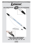
Fujifilm Dimatix DMP2831
Summary
• Part 1, Introduction to inkjet printed devices;
• Part 2, How to use the DMP2831;
• Part 3, DMP2831 advanced controls.
2
Part 1 - Introduction to inkjet printed
devices
• Why inkjet printing for the fabrication of
organic electronic devices?
• Examples;
• General description of Fujifilm DMP2831;
• Printing a Pattern with the DMP2831.
3
Why inkjet printing for the fabrication
of organic electronic devices?
R2R
Production
Cost
Lifetime
Efficiency
4
Drop on
Demand
Reproduc
ibility
Save
material
Samuele Lilliu - [email protected]
4
Part 1 - Introduction to inkjet printed
devices
• Why inkjet printing for the fabrication of
organic electronic devices?
• Examples;
• General description of Fujifilm DMP2831;
• Printing a Pattern with the DMP2831.
5
Example 1: Organic Photodiodes
• Inkjet Printed Organic
Photodiodes [1]
• Focus on:
– Inks optimization;
– DMP2831;
– Device fabrication.
• Inks:
– PEDOT: PSS;
– P3HT: PCBM.
[1] Lilliu, S. et al. Inkjet-printed organic photodiodes. Thin Solid
Films 520, 610-615, (2011).
6
Example 2: UWB Antenna
• Efficiency of a Compact
Elliptical Planar UltraWideband Antenna
Based on Conductive
Polymers [1]
• Inks:
– PEDOT;
– Polypyrrole (Ppy).
[1] Kaufmann, T. et al. Efficiency of a compact elliptical planar ultrawideband antenna based on conductive polymers. International
Journal of Antennas and Propagation 2012, (2012).
7
Example 3: Optical Humidity Sensor
• Printable Optical Sensors
Based on H-Bonded
Supramolecular Cholesteric
Liquid Crystal Networks [1];
• Ink: H-bonded CLC
materials;
• Relative humidity range
detection 3-83%
[1] Herzer, N. et al. Printable Optical Sensors Based on H-Bonded
Supramolecular Cholesteric Liquid Crystal Networks. J. Am. Chem.
Soc. 134, 7608-7611, (2012).
8
Example 4: H production from H2O
• Combinatorial Discovery
and Optimization of a
Complex Oxide with
Water Photoelectrolysis
Activity [1];
• Inks: 500 combinations
of Co3−x−yAlxFeyO4.
[1] Woodhouse, M. et al. Combinatorial Discovery and Optimization
of a Complex Oxide with Water Photoelectrolysis Activity. Chem.
Mater. 20, 2495-2502, (2008).
9
Example 5: Pesticides Detection
• Reagentless
Bidirectional Lateral
Flow Bioactive Paper
Sensors for Detection of
Pesticides in Beverage
and Food Samples [1];
[1] Hossain, S. M. Z. et al. Reagentless Bidirectional Lateral Flow
Bioactive Paper Sensors for Detection of Pesticides in Beverage and
Food Samples. Anal. Chem. 81, 9055-9064, (2009).
10
Example 6: Transparent/Flexible OFET
• Inkjet printing of
transparent, flexible,
organic transistors Inks
[1];
• Inks:
– PEDOT: PSS (electrodes);
– Pentacene (p-type);
– N1400 (n-type);
[1] Basiricò, L. et al. Inkjet printing of transparent, flexible, organic
transistors. Thin Solid Films 520, 1291-1294, (2011).
11
Example 7: OFET non-volatile Memory
• High-performance organic
charge trap flash memory
devices based on ink-jet
printed 6,13bis(triisopropylsilylethynyl)
pentacene transistors [1];
• Inks:
– Colloidal gold nanoparticles;
– Polymers (PAH/PSS/PAH);
– Low temperature curable
silver ink.
[1] Park, Y.-S. et al. High-performance organic charge trap flash memory devices based on ink-jet
printed 6,13-bis(triisopropylsilylethynyl) pentacene transistors. Appl. Phys. Lett. 96, -, (2010).
12
Part 1 - Introduction to inkjet printed
devices
• Why inkjet printing for the fabrication of
organic electronic devices?
• Examples;
• General description of Fujifilm DMP2831;
• Printing a Pattern with the DMP2831.
13
General description of Fujifilm
DMP2831
• DMP is a laboratory production tool for evaluating the use of ink
jetting technology for new manufacturing and analytical processes;
• Its resolution depends on the ink and on cartridge properties
(about 20um) [1].
Major components of the DMP
The DMP Printer Carriage
[1] Dimatix. Dimatix DMP-2800 User Manual, www.dimatix.com (2008).
Part 1 - Introduction to inkjet printed
devices
• Why inkjet printing for the fabrication of
organic electronic devices?
• Examples;
• General description of Fujifilm DMP2831;
• Printing a Pattern with the DMP2831.
15
Printing a Pattern (basic steps)
• Start the DMP;
• Open the DMP Drop Manager;
• Make sure the platen is
unobstructed;
• Install the Cartridge;
16
Printing a Pattern (basic steps)
• Start the DMP;
• Open the DMP Drop Manager;
• Make sure the platen is
unobstructed;
• Install the Cartridge;
• Replace the cleaning pad;
• Select Pattern to Print;
• Load/Unload Substrate;
– Make sure you select the right
substrate thickness;
• Vacuum
– Cover the holes on the platen.
17
Printing a Pattern (basic steps)
• Start the DMP;
• Open the DMP Drop Manager;
• Make sure the platen is
unobstructed;
• Install the Cartridge;
• Select Pattern to Print;
• Load/Unload Substrate;
– Make sure you select the right
thickness;
• Vacuum
– Cover the holes on the platen.
• Select Cartridge Settings;
• Print.
18
Part 2 - How to use the DMP2831
•
•
•
•
•
•
•
•
Compatible inks;
Filling and installing the cartridge;
How to unclog nozzles;
Install the cartridge;
Cartridge mounting angle;
Calibrate the nozzles view;
The Drop Watcher;
Designing a Waveform:
– Waveform shape;
– Velocities.
19
Part 2 - How to use the DMP2831
•
•
•
•
•
•
•
•
Compatible inks;
Filling and installing the cartridge;
How to unclog nozzles;
Install the cartridge;
Cartridge mounting angle;
Calibrate the nozzles view;
The Drop Watcher;
Designing a Waveform:
– Waveform shape;
– Velocities.
20
Compatible Inks
•
•
•
•
•
•
Viscosity – 10-12 centipoise at jetting
temperature;
Surface Tension – 28-33 dynes at jetting
temperature (1 dyne = 10−5 N);
Low Volatility – Boiling points higher than
100 deg. C are preferred;
Density – Specific gravity greater than 1 is
beneficial;
Degassing – Additionally the fluid may need
to be degassed to remove any dissolved gas
which inhibits jetting. Typical degassing can
be done by using ultrasonic;
Filtration – If particle size allows, it is
recommended to filter all fluids to 0.2µm.
21
Compatible Inks
22
Compatible Inks
23
Part 2 - How to use the DMP2831
•
•
•
•
•
•
•
•
Compatible inks;
Filling and installing a cartridge;
How to unclog nozzles;
Install the cartridge;
Cartridge mounting angle;
Calibrate the nozzles view;
The Drop Watcher;
Designing a Waveform:
– Waveform shape;
– Velocities.
24
Part 2 - How to use the DMP2831
•
•
•
•
•
•
•
•
Compatible inks;
Filling and installing a cartridge;
How to unclog nozzles;
Install the cartridge;
Cartridge mounting angle;
Calibrate the nozzles view;
The Drop Watcher;
Designing a Waveform:
– Waveform shape;
– Velocities.
25
Filling and Installing a Cartridge
with the Test Ink
•
•
•
•
•
•
•
•
•
•
•
Shake/sonicate well the ink container;
Fill the syringe with 2-4ml (you’ll lose ink
with the filter) of ink;
Connect filter (if filtering is required);
Connect special syringe;
Get rid of the air in the syringe (avoid air
bubbles);
Throw away the first 2 drops;
Carefully insert the needle into the Fill
Port;
Make sure there is a fluid bubble at the
Fill Port. Get rid of air bubbles;
Install the Jetting Module;
Let the cartridge rest for 30min with the
nozzles facing down (make sure the print
head is always facing down);
Make sure the channel connecting the Fill
Port to the Fluid Bag is completely filled
with fluid before printing.
26
Part 2 - How to use the DMP2831
•
•
•
•
•
•
•
•
Compatible inks;
Filling and installing a cartridge;
How to unclog nozzles;
Install the cartridge;
Cartridge mounting angle;
Calibrate the nozzles view;
The Drop Watcher;
Designing a Waveform:
– Waveform shape;
– Velocities.
27
How to unclog nozzles
• Use a large beaker;
• Fill it with a thin layer of the same solvent
used for the ink inside the cartridge;
• Put the nozzles in contact with the liquid,
without touching the bottom of the beaker;
• Push the cartridge up:
– Nozzles should unclog as an effect of the capillary
forces between the nozzles and the liquid.
28
Part 2 - How to use the DMP2831
•
•
•
•
•
•
•
•
Compatible inks;
Filling and installing a cartridge;
How to unclog nozzles;
Install the cartridge;
Cartridge mounting angle;
Calibrate the nozzles view;
The Drop Watcher;
Designing a Waveform:
– Waveform shape;
– Velocities.
29
Install the Cartridge
•
•
•
Open the DMP lid
– WARNING
Insert the cartridge into the cartridge
holder on the carriage with the electrical
connection pads towards the back of the
machine matching the connector of the
holder. There is only one way it will fit.
Push it down firmly so that it “clicks” into
place.
Pull the cartridge holder latch forward
and down until it locks in place. You will
hear a click. Check to see that the
cartridge is sitting flat in the holder.
30
Install the Cartridge
•
•
•
After the cartridge is installed, close the lid.
You should hear a pump turn on to control
the meniscus pressure.
The following window will pop-up.
Load the Cartridge Setting of the fluid that
you will use or, if your fluid has not a
Cartridge Setting, simply select the Dimatix
Model Fluid 2 Cartridge Setting as a starting
point .
31
Part 2 - How to use the DMP2831
•
•
•
•
•
•
•
•
Compatible inks;
Filling and installing a cartridge;
How to unclog nozzles;
Install the cartridge;
Cartridge mounting angle;
Calibrate the nozzles view;
The Drop Watcher;
Designing a Waveform:
– Waveform shape;
– Velocities.
32
Cartridge Mounting Angle
• Before you jet your pattern, the
system will calculate the angle to
set the cartridge determined by the
Grid Spacing specified in the
pattern. This angle adjustment is
what allows the user to modify the
drop spacing in the Y axis.
• There are two sets of scales on the
cartridge carriage. The outer scale is
the cartridge angle scale, and the
inner scale is the Vernier Scale to
adjust the head angle to 0.1 degree
increments. Release the latch by
pulling it forward freeing the
carriage plate to rotate.
33
Cartridge Mounting Angle
The Vernier Scale
• Uses a Vernier Scale such as the one
on the caliper;
• A Vernier Scale is an additional scale
on a measuring device that lets the
user read distance or angle
measurement more accurately than
could be done by reading a
uniformly-divided straight or circular
measurement scale.
• It is a sliding secondary scale that
indicates where the measurement
lies in between two of the marks on
the main scale.
34
Cartridge Mounting Angle
The Vernier Scale
Zero Degrees
11.4 Degrees
35
Part 2 - How to use the DMP2831
•
•
•
•
•
•
•
•
Compatible inks;
Filling and installing a cartridge;
How to unclog nozzles;
Install the cartridge;
Cartridge mounting angle;
Calibrate the nozzles view;
The Drop Watcher;
Designing a Waveform:
– Waveform shape;
– Velocities.
36
Calibrate Nozzles View
• Calibrate the nozzles to the
scale in the Drop Watcher;
• The system doesn’t know
where the nozzles are, and
this step should be performed
after a new cartridge is
installed;
• Right click on a reference
nozzle (e.g. 8)
• Tools -> Calibrate Nozzle View
• Follow the instructions in the
Instructions panel.
• If you cannot identify the
nozzle, activate it, and play
with the strobe delay.
37
Part 2 - How to use the DMP2831
•
•
•
•
•
•
•
•
Compatible inks;
Filling and installing a cartridge;
How to unclog nozzles;
Install the cartridge;
Cartridge mounting angle;
Calibrate the nozzles view;
The Drop Watcher;
Designing a Waveform:
– Waveform shape;
– Velocities.
38
The Drop Watcher (DW)
39
Part 2 - How to use the DMP2831
•
•
•
•
•
•
•
•
Compatible inks;
Filling and installing a cartridge;
How to unclog nozzles;
Install the cartridge;
Cartridge mounting angle;
Calibrate the nozzles view;
The Drop Watcher;
Designing a Waveform:
– Cartridge Settings;
– The Waveform Editor;
– Optimizing the waveform
40
Cartridge Settings
Cartridge Settings:
• Waveform;
• Cartridge;
• Cleaning Cycles.
41
The Waveform Editor
• Make sure the fluid meets the
cartridge specification in terms
of viscosity, surface tension,
and density;
• This is the most powerful
screen in the control software
regarding jetting fluids.
• On this screen you control the
shape of the pulse to the
nozzle to eject a drop. To
adjust a segment, simply point
your arrow to it and click on it.
The selected segment will
change from blue to red.
42
The Waveform Editor
43
The Waveform Editor
44
The Waveform Editor
45
The Waveform Editor
46
The Waveform Editor
47
Optimizing the Waveform
• Make sure your fluid
meets the specifications
for the cartridge;
• Open:
– Drop watcher;
– Cartridge settings;
– Waveform Editor
• Right click on nozzle 14
e.g.:
– The camera points on
the nozzle 14;
48
Optimizing the Waveform
•
•
•
If the selected nozzles do
not eject because the
cartridge has been sitting for
a while, run a purge cycle;
Take the system out of
movie mode by deselecting
‘Movie Mode’;
Change the strobe delay:
–
–
If a drop is at 300um from the
nozzle and the strobe delay is
53 microseconds, it means that
The drop speed is:
𝑣𝑑𝑟𝑜𝑝 =
•
𝑃𝑜𝑠𝑖𝑡𝑖𝑜𝑛 300 𝑚
=
𝐷𝑒𝑙𝑎𝑦
53 𝑠
𝑚
= 5.3
𝑠
Focus
49
Optimizing the Waveform
• Let’s have a closer look at the
jetting waveform;
• The present waveform is broken
up into 5 segments;
• The idled nozzles get the
waveform described by the non
jetting waveform;
– this might help preventing nozzles
clogging;
• We need to develop the base
pulse for the fluid;
• This is essentially tuning the
driving pressure pulse to the
acoustic properties of the fluid and
the physical characteristics of the
pumping chamber.
50
Optimizing the Waveform
•
•
Lets’ focus on the third segment.
The goal is to produce maximum velocity using
minimum voltage:
–
–
•
•
•
•
•
As we change the pulse width there will be a
change in the drop position.
If the drop moves farther away from the nozzle
this corresponds to an increase in velocity.
If we increase the duration of segment 3, the
velocity increases. This is good.
If we keep increasing the duration there will be a
point at which the drop, rather increasing velocity,
slows down. This happens at about 4us;
The range of duration for which the increase in
duration corresponds to an increase in the drop
speed is between 3 and 4us.
We now set all segments to 3us.
Drop speed
•
Drops should travel faster than 6 m/s;
The upper speed limit is about 10 m/s.
51
3
4
Third pulse width [us]
Optimizing the Waveform
• The delay 100 us is very
convenient because it allows
rapidly calculating the drop
speed
𝑣𝑑𝑟𝑜𝑝 =
𝑃𝑜𝑠𝑖𝑡𝑖𝑜𝑛 300 m
m
=
=3
100 𝜇𝑠
100 s
s
• This means that the waveform
should be adjusted so that
drops are between the 600um
and the 1000um line;
• Drops can be also moved by
slightly increasing the voltage.
52
Optimizing the Waveform
• By reducing the strobe delay we can
check the drop formation at the
nozzles;
– Ligament, drop formation mechanics
• Now the objective is to balance the
drop formation characteristics with
the drop velocities;
• How does a good drop look like?
• Segments 4 and 5 will have more
effect on the ligament;
• Segments 1 and 2 have more effect
on the overall velocity of the main
droplet.
53
Optimizing the Waveform
• By increasing Segment 5
amplitude:
– The ligament becomes
shorter (good);
– The velocity reduces (bad);
54
Optimizing the Waveform
• By increasing Segment 1
amplitude:
– The ligament becomes longer
(bad);
– The velocity increases;
• By further increasing the
amplitude of Segment 1:
– The ligament separates (satellite
droplet) from the main drop, which
is not desirable;
– Satellites and main drop might
have different velocities (bad)
– However if we increase Segment 5,
the ligament attaches again
• We need to play with both the
amplitudes.
55
Optimizing the Waveform
• Let’s play with segment 4;
• Segment 4 does not impact
the drop velocity, so we
leave it at the same
amplitude as segment 5;
• One of the objectives here
is to design the simplest
possible waveform.
56
Optimizing the Waveform
• If we set the strobe delay to
100us we can observe that the
drops excede the range of
velocities 6-10 m/s:
– Therefore we can reduce the
voltage;
• We check again the drop
formation;
• In order to make the waveform as
simple as possible we can try to:
– Delete Segment 5: this doesn’t
affect the drop formation nor the
drop velocity;
– Leave Segment 1 and 4 at the
sample amplitude and play with
their amplitude;
– Delete Segment 1.
57
Optimizing the Waveform
• Adjust the firing voltages for each nozzles so that
all the drops have the same velocity
58
Optimizing the Waveform
• Now that the drops look
good, the waveform can
be further optimized by
using the ‘Overall
Waveform Control’;
• Use only small changes
for the duration scaler
of 0.9 or 1.1;
• Save the Waveform file;
• Save the Jetting file.
59
Part 3 - DMP2831 advanced controls
•
•
•
•
Organize the working area;
Is the Printer OK? Print Test
Drop Diameter;
Design your pattern:
– Pattern Editor;
– How to work with B/W bitmaps
•
•
•
•
Cartridge mounting angle;
Offset Adjustment;
Print Test Pattern;
Print
60
Organize the working area
TEST
SUBSTRATE
SUBSTRATE
1
SUBSTRATE
2
SUBSTRATE
3
SUBSTRATE
4
Keep the same X, Y gap between substrates
Use a metal supporting mask (i.e. the one used used for metal evaporation)
61
Part 3 - DMP2831 advanced controls
•
•
•
•
Organize the working area;
Is the Printer OK? Print Test;
Drop Diameter;
Design your pattern:
– Pattern Editor;
– How to work with B/W bitmaps
•
•
•
•
Cartridge mounting angle;
Offset Adjustment;
Print Test Pattern;
Print
62
Is the Printer OK? Print Test
•
•
•
•
Model Fluid;
10pL cartridge;
Fill the cartridge;
Install the cartridge on the
printer and wait for 30 min;
• Run a purge cycle (2sec)
• Print Pattern: ‘Print Test
Troubleshooting’
• Cartridge Settings: ‘Print
Test Troubleshooting’
63
Print Test
• Open Cartridge
Settings;
• All nozzles: 25V,
enabled
• Cleaning cycle: purge 2
seconds
• Load a piece of paper.
64
Print Test
• The print pattern will
take most of the
paper, therefore the
origin should be set at
the left-hand side of
the paper;
• Set the print head at
22.3°
• Print
65
Print Test
• With the Fiducial Camera visually
inspect the printed pattern
• Each nozzles performance can be
evaluated (in this case the 14th didn’t
work)
• All of the lines should be straight and
consistent;
• Unconsistent lines are usually related
to the fluid and not to the hardware
66
Part 3 - DMP2831 advanced controls
•
•
•
•
Organize the working area;
Is the Printer OK? Print Test
Drop Diameter;
Design your pattern:
– Pattern Editor;
– How to work with B/W bitmaps
•
•
•
•
Cartridge mounting angle;
Offset Adjustment;
Print Test Pattern;
Print
67
Drop Diameter
• Use the Fiducial
Camera;
• Use a profilometer;
• (DO NOT USE AFM)
68
Part 3 - DMP2831 advanced controls
•
•
•
•
Organize the working area;
Is the Printer OK? Print Test
Drop Diameter;
Design your pattern:
– Pattern Editor;
– How to work with B/W bitmaps
•
•
•
•
Cartridge mounting angle;
Offset Adjustment;
Print Test Pattern;
Print
69
Pattern To Print
70
Pattern To Print
• Dimatix Pattern Editor
• Substrate:
– Dimensions:
• automatically calculated;
• total pattern dimension.
– Leader Bar:
• Vertical bar that can be jetted (by
checking the Enable box) which will
precede your pattern. This is often used
to “pre-fire” nozzles to keep them active
and their drop velocity uniform to
improve pattern quality. The Width of it
and the Gap of the Leader Bar can be
entered in the boxes.
– Drop Spacing: fundamental
• center to center distance from one drop
to the next in X and Y position
– Layers:
• Reprint the same pattern several times
(thickness control)
71
Pattern To Print
YWidth
YPitch
XWidth
XPitch
72
Pattern to Print
73
Part 3 - DMP2831 advanced controls
•
•
•
•
Organize the working area;
Is the Printer OK? Print Test
Drop Diameter;
Design your pattern:
– Pattern Editor;
– How to work with B/W bitmaps
•
•
•
•
Cartridge mounting angle;
Offset Adjustment;
Print Test Pattern;
Print
74
Cartridge mounting angle
• The Drop Spacing is the distance in X and Y, center to
center, of the drops that the DMP will deposit to create
the pattern;
• Drop Spacing is adjustable between 5 and 254 microns
in one micron increments;
• The Drop Spacing therefore determines your resolution
or density in the X direction and determines the angle
at which the cartridge must be set to get the same
resolution or density in the Y direction.
75
Calculate the mounting angle
76
Part 3 - DMP2831 advanced controls
•
•
•
•
Organize the working area;
Is the Printer OK? Print Test
Drop Diameter;
Design your pattern:
– Pattern Editor;
– How to work with B/W bitmaps
•
•
•
•
Cartridge mounting angle;
Offset Adjustment;
Print Test Pattern;
Print
77
Drop Offset Routine
• This procedure has to be
performed every time:
– the print head is removed;
– the print head angle has
changed
• In order for the Drop Offset
routine to be accurate, the
print head must already be
adjusted or setup, meaning
that the drop velocities for the
nozzles have been adjusted;
• Open the Drop Watcher and
make sure the drops have the
right velocity and that they
are aligned
78
Drop Offset Routine
•
•
•
Open the Fiducial Camera;
Option -> Don’t show Crosshairs;
Set a new print origin on the substrate (or a
test substrate):
–
–
–
–
–
•
•
If you press Move the carriage will move to
the grey box;
The Drop Offset routine will print a 16x1 mm
line on the substrate. At the end of the line
there is a single drop which is the calibration
drop
–
–
•
•
•
This can be done with the Platen map
The small red box is the current carriage
position;
The small green box is the current reference
point;
The small grey box is position the carriage will
move to, when the Move button is selected;
The red crosshair is the current print origin
the line is just a reference point;
The line is usually above the camera position.
Tools -> Set Drop Offset
Follow the instructions
If you cannot find the small drop DO NOT
GUESS : try again!
79
Further checks before printing
• Make sure all selected
nozzles are working;
• Print a test pattern in
the test sample.
80