1
Workshop Manual
H
2(0)
D25A MS, D25A MT
D30A MS, D30A MT
Plus d'informations sur : www.dbmoteurs.fr
Plus d'informations sur : www.dbmoteurs.fr
Marine Engines
D25A & D30A MS/MT
Content
Safety Information ................................................. 5
Introduction ............................................................ 5
Important ............................................................... 5
Warning labels D25A / D30A MS ........................... 8
Warning labels D25A / D30A MT ........................... 9
General Information ............................................. 10
About the Workshop Manual ............................... 10
Spare parts .......................................................... 10
Certified engines .................................................. 10
Repair instructions ............................................... 11
Our joint responsibility ......................................... 11
How to Use This Manual ..................................... 12
Terms used in this manual ................................... 12
Disassembly and Reassembly............................. 13
Presentation D25A/D30A MS .............................. 16
Presentation D25A/D30A MT .............................. 17
Identification numbers D25A/D30A ...................... 18
Specification D25A/D30A .................................... 19
Maintenance Standards Table ............................. 22
General................................................................ 22
Engine main parts ................................................ 23
Reassembly ......................................................... 27
Inlet and exhaust system ..................................... 31
Lubrication system............................................... 33
Cooling system .................................................... 34
Fuel system ......................................................... 36
Electric system .................................................... 39
Tightening torques D25A ..................................... 41
Tightening torques D30A ..................................... 43
Standard Bolts and Nuts ...................................... 45
Standard eyebolts ................................................ 45
Standard union nuts ............................................ 46
High pressure fuel injection pipes ........................ 46
Sealants and Lubricants Table ............................ 47
Special Tools ....................................................... 48
Determination of overhaul timing ......................... 51
Adjustment and Benchtesting .............................. 52
Valve Clearance .................................................. 52
Fuel system bleeding ........................................... 55
Fuel injection timing ............................................. 57
Speed setting ...................................................... 59
Measure V-belt deflection .................................... 60
Bench testing ....................................................... 61
Engine auxiliaries removal and installation .......... 62
Engine Auxiliaries Installation .............................. 69
Group 21 Engine Body ........................................ 73
Cylinder heads and valve mechanism ................. 73
Inspection and Repair .......................................... 76
Reassembly ......................................................... 83
Cylinder liners, Pistons and Connecting rods ...... 87
Inspection and Repair .......................................... 90
Reassembly ......................................................... 99
Viscous damper and front gears ........................ 103
Reassembly ....................................................... 105
Flywheel, Timing gears, Camshaft and Oilpan .. 106
Inspection and Repair ........................................ 109
Reassembly ....................................................... 113
Crankcase, Crankshaft and Main bearings ........ 117
Inspection and Repair ........................................ 119
Reassembly ....................................................... 126
Group 22 Lubrication system ............................. 128
Oil Pump and Safety Valve ................................ 128
Inspection .......................................................... 129
Reassembly ....................................................... 131
Relief valve ........................................................ 132
Inspection .......................................................... 132
Reassembly ....................................................... 132
Oil Cooler and Thermostat ................................ 133
Inspection .......................................................... 134
Reassembly ....................................................... 134
Plus d'informations sur : www.dbmoteurs.fr
3
Oil Filter, Filter Alarm, Relief Valve,
Left Side Cooler and Thermostat .........................
Inspection ..........................................................
Reassembly .......................................................
Group 23 Fuel System .......................................
Fuel Filters .........................................................
Reassembly .......................................................
Fuel Injectors .....................................................
Inspection and Adjustment ................................
Reassembly .......................................................
Fuel Injection Pump ...........................................
Inspection ..........................................................
Reassembly .......................................................
Adjustment of Injection Timing ...........................
Feed Pump ........................................................
Reassembly .......................................................
Testing ..............................................................
PSG Woodward Governor and Drive ................
Inspection ..........................................................
Reassembly .......................................................
Group 25 Inlet and Exhaust System ..................
Air Cooler ..........................................................
Inspection ..........................................................
Turbocharger [TD13] .........................................
Disassembly ......................................................
Inspection ..........................................................
Reassembly .......................................................
Turbocharger [TD15] .........................................
Disassembly ......................................................
Inspection ..........................................................
Reassembly .......................................................
Group 26 Cooling System ..................................
Fresh Water Pump ............................................
Inspection ..........................................................
Reassembly .......................................................
Thermostats ......................................................
Heat Exchanger .................................................
Raw Water Pump(standard rubber impeller) ......
Inspection ..........................................................
Reassembly .......................................................
Group 30 Electrical System ...............................
Starter ...............................................................
Inspection and Repair ........................................
Reassembly .......................................................
Alternator ...........................................................
Inspection and repair .........................................
Reassembly .......................................................
4
135
135
135
136
136
137
138
139
141
142
147
150
159
161
162
162
163
164
165
166
166
167
168
169
172
174
180
181
184
186
193
193
195
196
198
199
200
201
202
206
206
209
213
216
217
217
Plus d'informations sur : www.dbmoteurs.fr
Safety information
Safety Information
Introduction
The Manual contains technical data, descriptions, and repair instructions for the designated Volvo Penta engines
or engine versions. Make sure that the correct workshop literature is used.
Read the following safety information and the General Information and Repair Instructions in the Workshop Manual carefully before starting service work.
Important
The following special warning symbols are used in the Workshop Manual and on the engine.
WARNING! Warns of risk of bodily injury, serious damage to product or property, or that a serious malfunction can occur if the instructions are not followed.
IMPORTANT! Used to attract attention to things that can cause damage or malfunction to product or property.
NOTE! Used to attract attention to important information, to simplify work procedures or handling.
The following list provides an overview of the risks and cautionary procedures that should always be observed.
Prevent the engine from being started by disconnecting the power with the main switch
(switches) and locking it (them) in the disconnected position. Post warning signs stating
“Work in progress!” in every position from wich
the engine can be started.
Maintenance and service should be performed
on a stationary engine. However, some procedures, e.g. certain adjustments, require the engine to be running. Approaching an engine that
is running is a safety risk. Remember that loose
clothes or long hair can fasten in rotating parts
and cause severe injury.
A careless movement or dropped tool while
working in the vicinity of an engine that is running, can in the worst case lead to injury. Observe caution with hot surfaces (exhaust pipe,
turbo, charge air pipe, starter element etc.) and
hot fluids in the lines and hoses of an engine
that is running, or has just been stopped. Refit
all guards dismantled during service work before starting the engine.
Make sure that the warning or information decals on the product are always clearly visible.
Replace labels that have been damaged or
painted over.
Never start the engine unless the air filter is fitted. The rotating compressor wheel in the turbo
can cause severe injury. Foreign objects in the
inlet pipe can also damage the machine.
Never use starter spray or the like. Risk of in
the inlet pipe. Risk of personal injury.
Avoid opening the coolant filler cap when the
engine is hot. Steam or hot coolant can spray
out, and built up pressure will be lost. Open the
filler cap slowly and release the overpressure in
the cooling system if the filler cap or cock must
be opened, or if a plug or coolant pipe must be
removed when the engine is hot. Steam or hot
coolant can flow out in an unpredicted direction.
Plus d'informations sur : www.dbmoteurs.fr
5
Safety information
Hot oil can cause burn injuries. Avoid skin contact with hot oil. Make sure that the oil system is
not pressurised before working on it. Never
start, or run the engine with the oil filler cap removed due to the risk of ejecting oil.
Stop the engine and close the bottom valve before working on the cooling system.
Only start the engine in a well-ventilated area.
Exhaust fumes and crankcase gases should be
bled out of the engine compartment or workshop when working in closed environments.
Always use protective glasses for work where
there is a risk of splintering, sparks, or splashing of acid or other chemicals. The eyes are extremely sensitive, and an injury could cause
blindness!
Avoid skin contact with oil! Prolonged or frequent skin contact with oil can degrease the
skin, resulting in irritation, drying out, eczema,
and other skin complaints. Used oil is more
dangerous than new oil from a health care point
of view. Use protective gloves and avoid oildrenched clothes and rags. Wash your hands
regularly, especially before meals. Use special
hand cream to counteract drying out, and to
simplify cleaning the skin.
The majority of chemicals intended for the product (e.g. engine and timing gear oils, glycol,
petrol and diesel oil) or chemicals for workshop
use (e.g. degreasing agent, enamels and solvents) are hazardous to health. Read the instructions on the pack carefully. Always follow
the given safety instructions (e.g. the use of
breathing protection, protective glasses, or
gloves, etc.) Make sure that other personnel are
not exposed to hazardous substances, e.g. by
inhaling the air. Make sure there is adequate
ventilation. Handle consumed and surplus
chemicals in the prescribed manner.
Observe extreme caution when tracing fuel
leaks in fuel systems and when testing fuel nozzles. Wear protective glasses. The jet from a
fuel nozzle has a very high pressure and penetrating force. The fuel can penetrate deeply into
bodily tissue and cause serious injury. Risk of
blood poisoning.
6
All fuels, as well as many chemicals, are inflammable. Make sure no naked flames or sparks
can cause ignition. Petrol, certain thinners, and
hydrogen from batteries are extremely inflammable and explosive when mixed with air.
Smoking is prohibited! Ventilate well and take
the necessary precautions before welding or
grinding in the immediate vicinity. Always have
a fire extinguisher handy in the workshop.
Make sure that rags drenched in oil and petrol,
including old fuel and lubricant filters, are stored
safety. Oil drenched rags can in certain conditions self-ignite. Old fuel and oil filters are environmentally hazardous waste, and together with
spent lubricant, contaminated fuel, paint residue, solvent, degreasing agent and suds,
should be handed in to a waste-handling unit for
destruction.
Batteries must never be exposed to naked
flames or electrical sparks. Never smoke in the
vicinity of batteries. Hydrogen develops when
batteries are charged, which in combination
with air forms an explosive gas. This gas is
highly inflammable and very explosive. One
spark from connecting the batteries incorrectly
is sufficient to cause the battery to explode and
cause injury. Do not touch the connection when
starting (risk of spark) and do not lean over the
batteries.
Never confuse the plus and minus terminals
when fitting the batteries. This can cause serious damage to the electrical equipment. Check
the wiring diagram.
Always use protective glasses when charging
and handling batteries. The battery electrolyte
contains strongly corrosive sulphuric acid. Upon
contact with the skin, wash with soap and plenty of water. If battery acid gets into the eyes,
rinse immediately with water, and contact a
doctor without delay.
Stop the engine and turn off the power with the
main switch (switches) before working on the
electrical system.
The clutch should be adjusted when the engine
is idle.
Plus d'informations sur : www.dbmoteurs.fr
Safety information
Use the lifting hooks mounted on the engine/reversing gear when lifting the drive unit. Always
check that the lifting equipment is in good condition and has the correct capacity for the lift
(weight of engine plus reversing gear and extra
equipment where appropriate).
WARNING! The components in the electrical
system and fuel system on Volvo Penta products are designed and manufactured to minimise the risks of explosion and fire. The engine
must not be run in environments surrounded by
explosive media.
For safe handling, and to avoid damaging the
components mounted on top of the engine, the
engine should always be lifted with a lifting bar
adjusted to the engine. All chains or wires
should run in parallel with each other and as
perpendicular to the top of the engine as possible. Special lifting equipment may be required to
ensure the right balance and safe handling if
other equipment connected to the engine alters
its centre of gravity.
Pressure pipes must not bent, turned, or exposed to other strain. Replace damaged pressure pipes.
Never work on an engine supported only by lifting equipment.
Never work alone when heavy components are
to be dismantled, even when safe lifting (e.g.
lockable block and tackle) equipment is used. In
most cases, two persons are required even
when lifting equipment is used: one to handle
the equipment and one to make sure that components are not damaged. When working onboard a boat always make sure in advance that
there is sufficient space to allow dismantling in
situ, without the risk of personal injury or material damage.
Observe the following when cleaning with highpressure wash: Never point the jet of water at
seals, rubber hoses, or electrical components.
Never use the high-pressure function when
washing the engine.
Always use Volvo Penta recommended fuel.
See the instruction manual. The use of inferior
quality fuel could damage the engine. The use
of inferior fuel in a diesel engine could cause
the control rod to jam and the engine to overspeed, with the risk of personal injury or damage to the machine. Inferior fuel can also lead
to higher maintenance costs.
Plus d'informations sur : www.dbmoteurs.fr
7
Safety information
Warning labels D25A / D30A MS
The engine carries ‘Warning Labels’ at places where you are required to pay special attention. Please read them
carefully and make sure you understand the content of each label and the meaning of their position.
1.
Make sure the labels are legible. If you find any letter or picture illegible in a label, remove soil from the label,
or replace it.
2.
Clean the label with cloth and water or cleanser. Do not use organic solvent or gasoline, this would dissolve
the label’s adhesive and cause the label to fall off.
3.
If any label is damaged, lost or illegible, replace it. When replacing a label, make sure the new label is
identical to the old one. For new labels, please contact your dealer.
8
Plus d'informations sur : www.dbmoteurs.fr
Safety information
Warning labels D25A / D30A MT
The engine carries ‘Warning Labels’ at places where you are required to pay special attention. Please read them
carefully and make sure you understand the content of each label and the meaning of their position.
1.
Make sure the labels are legible. If you find any letter or picture illegible in a label, remove soil from the label,
or replace it.
2.
Clean the label with cloth and water or cleanser. Do not use organic solvent or gasoline, this would dissolve
the label’s adhesive and cause the label to fall off.
3.
If any label is damaged, lost or illegible, replace it. When replacing a label, make sure the new label is
identical to the old one. For new labels, please contact your dealer.
Plus d'informations sur : www.dbmoteurs.fr
9
General information
General Information
About the Workshop Manual
This Workshop Manual contains technical information, descriptions, and instructions for the standard versions of
the D25A and D30A engines. The engine designation and numbers are to be found on the engine identification
plate, refer to section “Identification numbers”. The motor designation and number should always be given during
all correspondence with Volvo Penta.
The Workshop Manual is primarily produced for Volvo Penta service workshops and their qualified personnel. It
is therefore assumed that persons using this manual have a basic knowledge of marine drive systems, and are
able to carry out the related mechanical and electrical nature. Volvo Penta is continuously developing their products. We therefore reserve the right to make changes. All the information contained in this book is based on
product data available prior to publication. Any essential changes or modifications in production or updated or revised service methods introduced after publication will be communicated by means of Service Bulletins.
Spare parts
Spare parts for the electrical and fuel systems are subject to different national safety requirements, e.g. U.S.
Coast Guard Safety Regulations. Volvo Penta Genuine Spare Parts comply with these requirements. All types of
damage resulting from the use of non genuine Volvo Penta spare parts for the product in question will not be regulated by the warranty undertakings of Volvo Penta.
Certified engines
For service and repair on an engine certificated for any area where exhaust emissions are regulated by law, the
following is important:
Certification means that an engine type is inspected and approved by the authorities. The engine manufacturer
guarantees that all engines manufactured of that type correspond to the certified engine.
This places special requirements on maintenance and service as follows:
●
The maintenance and service intervals recommended by Volvo Penta must be observed.
●
Only genuine Volvo Penta replacement parts may be used.
●
The service of injection pumps and injectors or pump settings must always be carried out by an authorized
Volvo Penta workshop.
●
The engine must not be modified in any way except with accessories and service kits approved by Volvo
Penta.
●
No modifications to the exhaust pipes and air supply ducts for the engine may be undertaken.
●
Seals may only be broken by authorized personnel.
Otherwise the general instructions contained in the Operator’s manual concerning operation, service and maintenance must be followed.
IMPORTANT! Neglected or deficient maintenance/service and the use of non-original spare parts will entail
Volvo Penta renouncing any responsibility for the engine corresponding to the certified version. Volvo Penta will not compensate for damage and/or costs arising from the above.
10
Plus d'informations sur : www.dbmoteurs.fr
General information
Repair instructions
The working methods described in the Service Manual apply to work carried out in a workshop. The engine has
been removed from the boat and is installed in an engine fixture. Unless otherwise stated reconditioning work
which can be carried out with the engine in place follows the same working method.
Warning symbols occurring in the Workshop Manual (refer to section “Safety information”) are not in any way
comprehensive since it is impossible to predict every circumstance under which service work or repairs may be
carried out. For this reason we can only highlight the risks that can arise when work is carried out incorrectly in a
well-equipped workshop using working methods and tools developed by us.
All procedures for which there are Volvo Penta special tools in this Workshop Manual are carried out using
these. Special tools are developed to rationalize working methods and make procedures as safe as possible. It is
therefore the responsibility of any person using tools or working methods other than the ones recommended by
us to ensure that there is no danger of injury, damage or malfunction resulting from these.
In some cases there may be special safety precautions and instructions for the use of tools and chemicals contained in this Workshop Manual. These special instructions should always be followed if there are no separate instructions in the Workshop Manual.
Certain elementary precautions and common sense can prevent most risks arising. A clean workplace and engine eliminates much of the danger of injury and malfunction.
It is of the greatest importance that no dirt or foreign particles get into the fuel system, cooling system, lubrication
system, intake system, turbocharger, bearings and seals when they are being worked on. The result can be malfunction or a shorter operational life.
Our joint responsibility
Each engine consists of many connected systems and components. If a component deviates from its technical
specification the environmental impact of an otherwise good engine may be increased significantly. It is therefore
vital that wear tolerances are maintained, that systems that can be adjusted are adjusted properly and that Volvo
Penta Genuine Parts as used. The engine Maintenance Schedule must be followed.
Some systems, such as the components in the fuel system, require special expertise and special testing equipment for service and maintenance. Some components are sealed at the factory for environmental reasons. No
work should be carried out on sealed components except by authorized personnel.
Bear in mind that most chemicals used on boats are harmful to the environment if used incorrectly. Volvo Penta
recommends the use of biodegradable degreasing agents for cleaning engine components, unless otherwise
stated in a workshop manual. Take special care when working on-board, that oil and waste is taken for destruction and is not accidentally pumped into the environment with bilge water.
Plus d'informations sur : www.dbmoteurs.fr
11
General information
How to Use This Manual
Terms used in this manual
1.
Parts in illustrations are numbered to correspond
with references to these numbers in text.
Before you read this manual, note that the following
special terms are used in dimensional and other
specifications.
2.
Items or conditions to be inspected during disassembly are listed in the disassembled views.
3.
Maintenance standards for inspection and repair
are described in text where relevant. For a quick
summary of maintenance standards refer to section “Maintenance Standards” of this manual.
4.
5.
12
The sequence in which parts are to be reassembled is summarized below each assembled view.
Such as:
Tightening torque under wet conditions is indicated as “(wet)” in text, drawings, and tables. When
so indicated, apply engine oil to the threaded portion of the fastener. Unless indicated as (wet), the
tightening torque should be dry.
Assembly standard
Indicates the dimension of a part, the dimension to be
attained at the time of reassembly or the standard
performance.
Norminal value
Indicates the standard dimension of a part.
Repair limit
A part which has reached this limit must be repaired.
Service limit
A part which has reached this limit must be replaced.
Standard clearance
Indicates the clearance to be obtained between mating parts at reassembly.
Plus d'informations sur : www.dbmoteurs.fr
General information
Disassembly and Reassembly
This service manual covers recommended procedures to be followed when servicing diesel engines. It also contains information on special tools required and basic safety precautions.
It is the responsibility of service personnel to be familiar with these requirements, precautions, and potential hazards and to discuss these points with their foreman or supervisor.
Study this manual carefully and observe the following general precautions to prevent serious personal injury and
to avoid damage to the engine, equipment, and parts.
WARNING! Use the correct tools and instruments. Serious injury or damage to the engine can result from
using the wrong tools and instruments
WARNING! When lifting or carrying heavy parts, get someone to help you if the part is too awkward for one
person to handle. Use jacks and chain blocks when necessary.
IMPORTANT! Use an overhaul stand or work bench if necessary.
IMPORTANT! Always read the Service Bulletins to learn about changes in procedures and/or technical data.
NOTE! Pay attention to the marks on assemblies, components, and parts for positions or directions. Put on your
own marks, if necessary, to aid reassembly.
NOTE! Carefully check each part for faults during removal or cleaning. Signs of abnormal wear will tell if parts or
assemblies are functioning improperly.
NOTE! Use assembly bins to keep the parts in order of removal and lay down disassembled or cleaned parts in
the order in which they were removed. This will save you time at reassembly
NOTE! Wash all engine parts, except oil seals, O-rings, rubber seals, etc. in cleaning solvent and dry them with
compressed air
NOTE! Use a torque wrench to tighten parts when specified tightening torques are required.
NOTE! Use only good quality lubricating oils and greases. Be sure to apply a coat of oil, grease, or sealant before reassembly, to parts as specified.
NOTE! Replace all gaskets and packing. Apply appropriate amount of adhesive or liquid gasket when required.
NOTE! Always apply “high temperature anti-seizing compound” to bolts and nuts that are exposed to high temperatures, e.g. exhaust manifold, turbo charger, exhaust flanges, etc.
Plus d'informations sur : www.dbmoteurs.fr
13
General information
Oil Seals
When installing oil seals, carefully observe the following points.
Driving oil seals into housings
1.
Check the seal lip for damage, and be sure to position correctly in the housing.
2.
Apply a smear of grease to the surface of the oil
seal (to be fitted into the housing bore).
3.
Use an oil seal driver shown to guide the seal lip
and drive the outer diameter squarely. To avoid
damage to the oil seal and leaking, never hammer on it directly.
Driving oil seals onto shafts
1.
Apply a smear of grease to the oil seal lip.
2.
Use an oil seal guide of the type shown when
driving the oil seal over the stepped portion,
splines, threads, or key way to prevent damage
to the oil seal lip.
O-rings
Use an O-ring guide to install an O-ring over stepped
parts, splines, threads, or key way to prevent damage
to the ring. Apply a smear of grease to the O-ring before installation.
14
Plus d'informations sur : www.dbmoteurs.fr
General information
Bearings
1.
When installing a rolling bearing, be sure to push
the inner or outer race by which the bearing is fitted. Be sure to use a bearing driver like the one
shown.
2.
Whenever possible, use a press to minimize
shock to the bearing and to assure proper installation.
Lock Plates
Bend lock plates against the flats of the nuts or bolt
heads as shown.
Split Pins and Spring Pins
Generally, split pins are to be replaced once disturbed. Insert the pin fully and spread it properly.
Drive each spring pin into position to hold it in place
after later installation of parts has been completed.
Plus d'informations sur : www.dbmoteurs.fr
15
General information
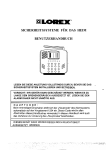
Presentation D25A/D30A MS
D25A/D30A MS
1. Fuel filters
2. Oil cooler
3. Fuel injection pump
4. Governor oil filter
5. Manual stop lever
6. Governor
7. Stop solenoid
8. Oil dipstick
9. Fuel feed pump
10. Oil filler cap
11. Fresh water pump
12. Lifting eye
13. Intake air silencer
14. Turbocharger
15. Charge air cooler
16. Alternator
17. By-pass filter for engine oil
18. Oil filters
19. Engine oil drain pipe
20. Starter motor
16
Plus d'informations sur : www.dbmoteurs.fr
General information
Presentation D25A/D30A MT
D25A/D30A MT
1. Fuel filters
2. Oil cooler
3. Fuel injection pump
4. Governor oil filter
5. Manual stop lever
6. Governor
7. Stop solenoid
8. Oil dipstick
9. Fuel feed pump
10. Oil filler cap
11. Fresh water pump
12. Lifting eye
13. Intake air silencer
14. Turbocharger
15. Charge air cooler
16. Heat exchanger
17. By-pass filter for engine oil
18. Oil filters
19. Starter motor
20. Engine oil drain pipe
21. Sea water pump
22. Alternator
Plus d'informations sur : www.dbmoteurs.fr
17
General information
Identification numbers D25A/D30A
Type plates with identification numbers can be found on the engine and the transmission or generator. This information must always be used as a reference when ordering service and spare parts.
Engine ........................................................................................................................................
Product designation ....................................................................................................................
Serial and basic engine number .................................................................................................
Product number ..........................................................................................................................
Certification, IMO ........................................................................................................................
Decal, part No. ...........................................................................................................................
Approval No. ...............................................................................................................................
Transmission / Generator ...........................................................................................................
Product designation ....................................................................................................................
Serial number .............................................................................................................................
Product number ..........................................................................................................................
18
Plus d'informations sur : www.dbmoteurs.fr
General information
Specification D25A/D30A
General specification
Model ...........................................................................
Water-cooled,4-stroke, turbocharged diesel with intercooler
No. of cylinders ............................................................
6
Arrangement ................................................................
in-line
Combustion type ..........................................................
Direct injection
Valve mechanism ........................................................
Overhead
Cylinder bore,mm [in.] ..................................................
170[6.70]
Cylinder stroke,mm [in.] ...............................................
180 [7.10]
Displacement, litres [U.S. gal] .....................................
24.51 [6.47]
Compression ratio ........................................................
14.0:1
Firing order ...................................................................
1-5-3-6-2-4
Rotational direction ......................................................
Counterclockwise as viewed from flywheel
Engine support method ................................................
4 point support
Weight (Dry)(without marine gear), kg [lb] ...................
D25A MS
D25A MT
D30A MS
D30A MT
.....................................................................................
2320[5115]
2900 [6395]
2420 [5335]
3000 [6615]
Engine main parts
Cylinder liner type ........................................................
Wet type
Piston rings:
Compression rings, pcs ...............................................
2
Oil ring(w/expander), pcs .............................................
1
Valve timing (when warm):
Inlet valve .....................................................................
open BTDC 37°
Inlet valve .....................................................................
close ABDC 44°
Exhaust valve ..............................................................
open BBDC 57°
Exhaust valve ..............................................................
close ATDC 24°
Fuel system
Fuel
JIS K2204 ....................................................................
TYPE 1, TYPE 2, TYPE 3
ASTM. D975 ................................................................
No.1-D, No.2-D
BS2869 ........................................................................
CLASS-A1, CLASS-A2,
DIN51601 .....................................................................
DIESEL-FUEL
ISO8217 .......................................................................
DMX-CLASS
Injection pump
Model ...........................................................................
PS6 type
Manufacturer ................................................................
Mitsubishi Heavy Industries, Ltd.
Plunger outside diam., mm [in.] ...................................
17 [0.67]
Plunger lead, mm [in.] ..................................................
Counterclockwise, left-hand 35 [1.38] lead
Cam lift, mm [in.] ..........................................................
15 [0.59]
Fuel feed pump
Model ...........................................................................
Zexel
Manufacturer ................................................................
Zexel
Cam lift, mm [in.] ..........................................................
12 [0.47]
Governor
Control system .............................................................
Woodward Hydraulic PSG
Plus d'informations sur : www.dbmoteurs.fr
19
General information
Fuel system cont.
Fuel injector
Type .............................................................................
Hole type
Manufacturer ................................................................
Zexel
No. of spray holes ........................................................
10
Spray hole diameter, mm [in.] ......................................
0.325 [0.013]
Spray angle, deg. .........................................................
160°
Injection press., Mpa(kgf/cm²)[psi] ..............................
34.32 to 34.81 (350 to 355) [4979 to 5050]
Fuel filter
Type .............................................................................
Paper element cartridge changeover, spin-on type
Oil system
Lubricating type ...........................................................
Forced circulation type (pressure feed by oil pump)
Engine oil Standard ......................................................
CF oil (API service classification) or better
Engine oil volume:
Oil sump,liter [U.S. gal] ................................................
140 [37.0] approx
Complete engine, liter [U.S. gal] ..................................
160 [42.3] approx
Oil pump
Type .............................................................................
Gear pump
Delivery capacity, liter [U.S. gal] ..................................
325 [85.9] (at engine speed 1650 rpm)
Relief valve
Type .............................................................................
Piston valve type
Opening press., MPa(kgf/cm³)[psi] ..............................
0.46 (4.7) [67]
Oil cooler
Type .............................................................................
Water-cooled, multi-plate type (housed in the engine block)
Full-flow oil filter
Type .............................................................................
Paper element changeover type (spin on)
By-pass oil filter
Type .............................................................................
Paper element type (spin on)
Oil thermostat
Type .............................................................................
Wax type
Valve opening temp., °C [°F] .......................................
80 to 84 [176 to 183.2]
Cooling system
Cooling type .................................................................
Water-cooled, forced circulation
Coolant capacity (engine only), liter [U.S. gal] ............
D25A MS
D25A MT
D30A MS
D30A MT
.....................................................................................
50 [13.2]
115 [30.4]
55 [14.5]
120 [31.7]
Fresh water pump
Type .............................................................................
Centrifugal
Pump capacity, liter [U.S. gal]/min. ..............................
800 [211], Total head 0.20 MPa (20 mAq) (at 2925 rpm pump speed)
Pump drive belt type ....................................................
V-belt
Outside circumference, mm [in] ...................................
1535 [60]
Thermostat
Type .............................................................................
Wax
Valve opening temp.,°C [°F] ........................................
71+/-2 [160+/- 35.6]
Valve fully opened, °C [°F] ...........................................
85+/-2 [185+/- 35.6]
Raw water pump (only on MT)
Type .............................................................................
Rubber rotor
Pump capacity, liter [U.S. gal]/min. ..............................
450 [119], Total head 0.10 MPa (10 mAq)(at 1800 rpm pump speed)
20
Plus d'informations sur : www.dbmoteurs.fr
General information
Inlet and exhaust system
Turbocharger
Type .............................................................................
TD13 or TD15
No. of units ...................................................................
1
Electrical system
Voltage-polarity ............................................................
24V earth float
Starter
Manufacturer ................................................................
Nikko Electric Industry
Pinion mesh type .........................................................
Pinion shift (Reduction type)
Output ..........................................................................
V (kW) 24 (7.5)
No. of starters ..............................................................
2
No. of pinion tooth/ring gear tooth ...............................
11 / 182
Alternator
Type .............................................................................
3-Phase alternating generator, Internal IC regulator
Manufacturer ................................................................
Mitsubishi Electric
Output ..........................................................................
V-A 24-35
Rated generated ..........................................................
27V, 35A at 5000 rpm
Regulated voltrage .......................................................
V 28.5 +/- 0.5
Drive belt:
type ..............................................................................
V-belt
outside circumference, mm [in.] ...................................
1250 [49]
Plus d'informations sur : www.dbmoteurs.fr
21
Maintenance Standards
Maintenance Standards Table
General
Maximum rpm
Nominal Value ...........
5 – 10 % higher than rated rpm
Repair limit ................ Lower or 20 % higher than rated rpm
NOTE! Rated rpm stamped on the nameplate. Check governor setting.
Minimum rpm
Nominal value ...........
600 to 650 rpm
Compression pressure MPa (Bar) [psi]
Nominal Value ...........
2.85 (28.5) [263] minimum (at 120 rpm)
Repair limit ................ 2.30 (23.0) [185] or lower
NOTE! Oil and water temp. 20 to 30°C [68 to 86°F]
Lube oil pressure MPa (Bar) [psi]
Nominal Value ...........
0.5 (5.0) [72]
At idling speed .......... 0.20 – 0.29 (2.0 – 2.9) [28 to 43]
Repair limit ................ 0.10 (1.0) [14] or lower at idling speed
NOTE! Oil temp. 60 to 70°C [140 to 158°F]
Valve timing
(2 mm[0.8 in.] clearance valve side, cold)
Nominal Value:
Inlet valve opens ....... 2.5° BTDC ±2° (crank angle)
Inlet valve closes ......
13° ABDC ±2° (crank angle)
Exh. valve opens ......
26° BBDC ±2° (crank angle)
Exh. valve closes ......
10.5° BTDC ±2° (crank angle)
NOTE! Values are only for checking valve timing and are different from the actual ones.
Valve clearance (cold), mm [in.]
Inlet valves:
Standard Clearance .. 0.6 [0.024]
Exhaust valves:
Standard Clearance .. 0.8 [0.031]
Injection timing
Nominal Value ...........
XX° BTDC ±1° (crank angle)
NOTE! XX varies according to specifications. Refer to caution plate on No. 1 rocker cover.
22
Plus d'informations sur : www.dbmoteurs.fr
Maintenance Standards
Engine main parts
Valves
Valve stem diameter, mm [in.]
Nominal Value ...........
Ø10 [0.39]
Assembly Standard ... 9.940 to 9.960 [0.39134 to 0.39213]
Service Limit ............. 9.910 [0.39016]
NOTE! The same for both inlet and exhaust valves.
Valve guide inside diameter, mm [in.]
Nominal Value ...........
Ø10 [0.39]
Assembly Standard ... 10.000 to 10.015 [0.39370 to 0.39429]
Service Limit ............. 10.060 [0.39606]
NOTE! The same for both inlet and exhaust valves.
Valve seat angle(A)
Nominal Value ...........
30°
Valve depth(B), mm [in.]
Nominal value ...........
0
Assembly Standard ... -2.0 – 0.2 [-0.008 – 0.008]
Repair Limit ............... 1.0 [0.039]
Seat width(C), mm [in.]
Nominal value ...........
2.3 [0.091]
Assembly Standard ... 2.15 to 2.45 [0.0846 to 0.0965]
Repair Limit ............... 2.8 [0.110]
Valve margin(D), mm [in.]
Nominal Value ...........
3.0 [0.12]
Assembly Standard ... 2.8 – 3.2 [0.110 to 0.126]
NOTE! Refacing permissible up to 2.5 [0.098]
Cylinder head bore and valve seat diameter, mm [in.]
Nominal Value ...........
Ø60 [2.36]
Assembly Standard ... -0.070 – -0.130 [-0.00276 – -0.00512]
NOTE! - (minus) indicates interference
Valve springs
Free length (A), mm [in.]
Assembly standard ... 73 [2.87]
Service limit .............. 71 [2.80]
Perpendicularity (B), mm [in.]
Service limit .............. 2.2 [0.087] (at end)
Length under test force, mm [in.]
Assembly standard ... 66.0 [2.6]
Test force, N (kgf) [lbf]
Assembly standard ... 289–319 (29.45 to 32.55) [65 to 72]
Plus d'informations sur : www.dbmoteurs.fr
23
Maintenance Standards
Valve push rods
Deflection, mm [in.]
Assembly Standard ... 0.5 [0.020] maximum
Service Limit ............. 0.5 [0.020]
Rockers
Rocker bushing inside diameter, mm [in.]
Nominal Value ...........
Ø36 [1.42]
Assembly Standard ... 36.000 to 36.040 [1.41732 to 1.41889]
Service Limit ............. 36.090 [1.42086]
Rocker shaft diameter, mm [in.]
Nominal Value ...........
Ø36 [1.42]
Assembly Standard ... 35.966 to 35.991 [1.41598 to 1.41697
Service Limit ............. 35.940 [1.41496]Cylinder heads
Cylinder head
Flatness of gasket surface, mm [in.]
Assembly Standard ... 0.03 [0.0012] or less
Repair Limit ............... 0.07 [0.0028]
Service Limit ............. 0.50 [0.0197]
NOTE! Reface if necessary
Thickness of gasket when tightened, mm [in.]
Nominal Value ...........
1.8 [0.07]
Assembly Standard ... 1.77 to 1.83 [0.0697 to 0.0720]
Cylinder liners
Inside diameter, mm [in.]
Nominal Value ...........
Ø170 [6.69]
Assembly Standard ... 170.000 to 170.040 [6.69290 to 6.69447]
Repair Limit ............... 170.200 [6.70078]
Service Limit ............. 170.500 [6.71259]
Roundness, mm [in.]
Assembly Standard ... 0.02 [0.0008] or less
Cylindricity, mm [in.]
Assembly Standard ... 0.02 [0.0008] or less
Squareness of flange lower face to liner center line, mm [in.]
Assembly Standard ... 0.03 [0.0012] or less
Protrusion of cylinder liner at flange, mm [in.]
Assembly Standard ... 0.11 to 0.20 [0.0043 to 0.0089]
Pistons and cylinderheads
Clearance between piston top and cylinder head, mm [in.]
Standard Clearance .. [1.22 to 1.95) ([0.0480 to 0.0768])
24
Plus d'informations sur : www.dbmoteurs.fr
Maintenance Standards
Pistons
Outside diameter, mm [in.]
Nominal Value ...........
Ø170 [6.69]
Assembly Standard ... 169.76 to 169.80 [6.6835 to 6.6850]
Service Limit ............. 169.66 [6.6795]
NOTE! Meaure diameter perpendicular to pin at piston skirt.
Weight difference between pistons in one engine
Assembly Standard ... ±10 g [±0.35 oz]
NOTE! Only one type of piston available for service replacement.
Pin bore diameter, mm [in.]
Nominal Value ...........
Ø70 [2.76]
Assembly Standard ... 70.002 to 70.015 [2.75598 to 2.75649]
Service Limit ............. 70.040 [2.75747]
Protrusion, mm [in.]
Assembly Standard ... 0.06 to 0.65 [0.0024 to 0.0256]
NOTE! From the cylinder block
Piston rings
Gaps Top ring, mm [in.]
Assembly Standard ... (0.6 to 0.8) ([0.024 to 0.031])
Service Limit ............. (2.0) ([0.079])
NOTE! If gauge is not available, the general value can be obtained at the cylinder bore.
Gaps Second ring, mm [in.]
Assembly Standard ... (0.6 to 0.8) ([0.024 to 0.031])
Service Limit ............. (2.0) ([0.079])
NOTE! If gauge is not available, the general value can be obtained at the cylinder bore.
Gaps Oil ring, mm [in.]
Assembly Standard ... (0.3 to 0.45) ([0.012 to 0.018])
Service Limit ............. (2.0) ([0.079])
NOTE! If gauge is not available, the general value can be obtained at the cylinder bore.
Piston pins
Diameter, mm [in.]
Nominal Value ...........
Ø70 [2.76]
Assembly Standard ... 69.987–70.000 [2.75539 to 2.75590]
Service Limit ............. 69.970 [2.75472]
Plus d'informations sur : www.dbmoteurs.fr
25
Maintenance Standards
Connecting rods
Bushing inside diameter, mm [in.]
Nominal Value ...........
Ø70 [2.76]
Assembly Standard ... 70.020–70.040 [2.75669 to 2.75747]
Service Limit ............. 70.070 [2.75866]
Bend and twist, mm [in.]
Assembly Standard ... 0.05/100 [0.0020/3.9] or less
End play (rod and crankpin widths), mm [in.]
Nominal Value ...........
67 [2.64]
Assembly Standard ... (0.2–0.6) ([0.008 to 0.016])
Service Limit ............. (1.0) ([0.039])
Weight difference between connecting rods in one engine
Assembly Standard ... ±30 g [±1.06 oz]
NOTE! All connecting rods in one engine must be with the same classification letter.
Big end bore diameter, mm [in.]
Nominal Value ...........
Ø131 [5.16]
Assembly Standard ... 131.000 to 131.025 [5.15747 to 5.15845]
Service Limit ............. 131.050 [5.15944]
NOTE! To be measured in combination with caps. Roundness less than (0.1 mm [0.004 in.] - service limit)
Connecting rod bearings
Thickness of center, STD, mm [in.]
Nominal Value ...........
3.000 [0.11811]
Assembly Standard ... 2.972 to 2.985 [0.11701 to 0.11752]
Service Limit* ............ 2.930 [0.11535]
Thickness of center, –0.25 [–0.0098], mm [in.]
Nominal Value ...........
3.125 [0.12303]
Assembly Standard ... 3.097 to 3.110 [0.12193 to 0.12244]
Service Limit* ............ 3.055 [0.12028]
Thickness of center, –0.50 [–0.0197], mm [in.]
Nominal Value ...........
3.250 [0.12795]
Assembly Standard ... 3.222 to 3.235 [0.12685 to 0.12736]
Service Limit* ............ 3.180 [0.12520]
Thickness of center, –0.75 [–0.0295], mm [in.]
Nominal Value ...........
3.375 [0.12287]
Assembly Standard ... 3.347 to 3.360 [0.13177 to 0.13228]
Service Limit* ............ 3.305 [0.13012]
Thickness of center, –1.00 [–0.0394], mm [in.]
Nominal Value ...........
3.500 [0.13780]
Assembly Standard ... 3.472 to 3.485 [0.13669 to 0.13720]
Service Limit ............. 3.430 [0.13504]
*NOTE! Replace bearings if worn down to service limit. Regrind crankpins and use undersize bearings if necessary.
26
Plus d'informations sur : www.dbmoteurs.fr
Maintenance Standards
Flywheel
Face runout, mm [in.]
Assembly Standard ... 0.285 [0.0112] to less
Radial runout, mm [in.]
Assembly Standard ... 0.127 [0.0050] or less
Injection pump accessory drive
Bearing bore inside diameter, mm [in.]
Nominal Value ...........
Ø90 [3.54]
Assembly Standard ... 89.987 – 90.022 [3.54279 – 3.54417]
Bearing bore inside diameter, mm [in.]
Nominal Value ...........
Ø100 [3.94]
Assembly Standard ... 99.987– 100.022 [3.93649 – 3.93787]
Bearing, Outside diameter, mm [in.]
Nominal Value ...........
Ø90 [3.54]
Assembly Standard ... 89.985 – 90.000 [3.54272 – 3.54331]
Bearing, Outside diameter, mm [in.]
Nominal Value ...........
Ø100 [3.94]
Assembly Standard ... 99.985 – 100.000 [3.93642 – 3.93701]
Bearing, Inside diameter, mm [in.]
Nominal Value ...........
Ø45 [1.77]
Assembly Standard ... 44.988 to 45.000 [1.77118 to 1.77165]
Bearing, Inside diameter , mm [in.]
Nominal Value ...........
Ø50 [1.97]
Assembly Standard ... 49.988 to 50.000 [1.96803 to 1.96850]
Drive shaft bearing journal diameter, mm [in.]
Nominal Value ...........
Ø45 [1.77]
Assembly Standard ... 45.002 to 45.013 [1.77173 to 1.77216]
Drive shaft bearing journal diameter, mm [in.]
Nominal Value ...........
Ø50 [1.97]
Assembly Standard ... 50.002 to 50.013 [1.96858 to 1.96901]
Damper
Radial runout (at periphery), mm [in.]
Assembly Standard ... 0.5 [0.020] or less
Service Limit ............. 1.5 [0.059]
Radial runout (at periphery), mm [in.]
Assembly Standard ... 0.5 [0.020] or less
Service Limit ............. 1.5 [0.059]
Plus d'informations sur : www.dbmoteurs.fr
27
Maintenance Standards
Timing gears
Backlash, mm [in.]
Assembly Standard ... (0.12 to 0.18) ([0.0047 to 0.0071])
Repair Limit ............... (0.30) ([0.0118])
Service Limit ............. (0.50) ([0.0197])
Idle gear shaft bushing inside diameter, mm [in.]
Nominal value ...........
Ø50 [1.97]
Assembly standard ... 50.000–50.025 [1.96850–1.96848]
Service limit .............. 50.060 [1.97086]
Idle gear shaft diameter, mm [in.]
Nominal value ...........
Ø50 [1.97]
Assembly standard ... 49.950–49.975 [1.96653–1.96752]
Service limit .............. 49.900 [1.96456]
Idle gear end play, mm [in.]
Standard clearance ... 0.2–0.4 [0.008–0.016]
Service limit .............. 0.6 [0.024]
Camshaft
Cam lift (A-B), mm [in.]
Nominal Value ...........
9.247 [0.36405]
Assembly Standard ... 9.197 to 9.297 [0.36209 to 0.36602]
Service Limit ............. 8.45 [0.3327]
Deflection, mm [in.]
Assembly Standard ... 0.05 [0.0020] or less
Repair Limit ............... 0.08 [0.0031]
NOTE! Deflection at center bushing measured with both ends supported. Repair or replace, if necessary.
Journal diameter, mm [in.]
Nominal Value ...........
Ø84 [3.31]
Assembly Standard ... 83.92 to 83.94 [3.3039 to 3.3047]
Service Limit ............. 83.87 [3.3020]
Camshaft bushing inside diameter (as installed in crank case), mm [in.]
Nominal Value ...........
Ø84 [3.31]
Assembly Standard ... 84.00 to 84.035 [3.30708 to 3.30846]
Service Limit ............. 84.10 [3.3110]
NOTE! Replace bushings and ream them, if necessary
End play, mm [in.]
Nominal Value ...........
8 [0.3]
Assembly Standard ... 0.10 to 0.25 [0.0039 to 0.0098]
Service Limit ............. 0.40 [0.0157])
NOTE! Replace thrust bearing, if necessary.
28
Plus d'informations sur : www.dbmoteurs.fr
Maintenance Standards
Crankshaft
Crankshaft pin diameter, mm [in.]
Nominal Value ...........
Ø125 [4.92]
Assembly Standard ... -0.050 – -0.070 [0.00197 – -0.00276]
Repair Limit ............... -0.110 [-0.00433]
Crankshaft journal diameter, mm [in.]
Nominal Value ...........
Ø140 [5.51]
Assembly Standard ... -0.050 – -0.070 [0.00197 – -0.00276]
Repair Limit ............... -0.110 [-0.00433]
Journal and crankpin center to center distance, mm [in.]
Nominal Value ...........
90 [3.54]
Assembly Standard ... ±0.1 [±0.004]
Parallelism between journals and crankpins, mm [in.]
Assembly Standard ... 0.01 [0.0004] or less at pin length
Repair Limit ............... 0.03 [0.0012]
Roundness of journals and crankpins, mm [in.]
Assembly Standard ... 0.01 [0.0004] or less in diameters
Repair Limit ............... 0.03 [0.0012]
Cylindricity of journals and crankpins, mm [in.]
Assembly Standard ... 0.02 [0.0008] or less in diameters
Repair Limit ............... 0.03 [0.0012]
Fillet radius of crankpins, mm [in.]
Nominal Value ...........
7 [0.28]
Assembly Standard ... 7.0 – 7.2 [0.268 – 0.276]
Fillet radius of journals, mm [in.]
Nominal Value ...........
7 [0.28]
Assembly Standard ... 7.0 – 7.2 [0.268 – 0.276]
Hardness of journals and crankpins
Assembly Standard ... Hv>620
Angularity
Assembly Standard ... ±0°20’
Deflection, mm [in.]
Assembly Standard ... 0.04 [0.0016] or less
Repair Limit ............... 0.10 [0.0039]
NOTE! Repair or replace if necessary
Thrustbearing journal length, mm [in.]
Nominal Value ...........
66 [2.60]
Crankshaft end play, mm [in.]
Nominal Value ...........
66 [2.60]
Assembly Standard ... 0.20 to 0.40 [0.0079 to 0.0157]
Service Limit ............. 0.50 [0.0197] (+ 1.18[0.0465] crank shaft width)
NOTE! Replace thrust bearings if worn down to service limit. Use oversize thrust bearings if worn beyond repair limit.
Plus d'informations sur : www.dbmoteurs.fr
29
Maintenance Standards
Main bearing
Thickness of center, STD, mm [in.]
Nominal Value ...........
3.500 [0.138]
Assembly Standard ... 3.467 to 3.480 [0.13650 to 0.13701]
Service Limit ............. 3.425 [0.13484]
NOTE! Replace bearings if worn down to service limit. Regrind crankpins and use undersize bearings if worn beyond service limit.
Thickness of center, –0.25 [–0.0098], mm [in.]
Nominal Value ...........
3.625 [0.14272]
Assembly Standard ... 3.592 to 3.605 [0.14142 to 0.14193]
Service Limit ............. 3.550 [0.13976]
NOTE! Replace bearings if worn down to service limit. Regrind crankpins and use undersize bearings if worn beyond service limit.
Thickness of center, –0.50 [–0.0197], mm [in.]
Nominal Value ...........
3.750 [0.14764]
Assembly Standard ... 3.717 to 3.730 [0.14634 to 0.14685]
Service Limit ............. 3.675 [0.14468]
NOTE! Replace bearings if worn down to service limit. Regrind crankpins and use undersize bearings if worn beyond service limit.
Thickness of center, –0.75 [–0.0295], mm [in.]
Nominal Value ...........
3.875 [0.15256]
Assembly Standard ... 3.842 to 3.855 [0.15126 to 0.15177]
Service Limit ............. 3.800 [0.14961]
NOTE! Replace bearings if worn down to service limit. Regrind crankpins and use undersize bearings if worn beyond service limit.
Thickness of center, –1.00 [–0.0394], mm [in.]
Nominal Value ...........
4.000 [0.15748]
Assembly Standard ... 3.967 to 3.980 [0.15618 to 0.15669]
Service Limit ............. 3.925 [0.15453]
NOTE! Replace bearings if worn down to service limit. Regrind crankpins and use undersize bearings if worn beyond service limit.
Crankcase
Flatness of gasket surface, mm [in.]
Assembly Standard ... 0.1 [0.004] or less
Repair Limit ............... 0.2 [0.008]
NOTE! Reface if necessary
Main bearing bore diameter, mm [in.]
Nominal Value ...........
Ø147 [5.79]
Assembly Standard ... 147.000 to 147.025 [5.78739 to 5.78837]
Service Limit ............. 147.035 [5.78877]
30
Plus d'informations sur : www.dbmoteurs.fr
Maintenance Standards
Inlet and exhaust system
Turbocharger TD13
Inside diameter of bearing-fitted housing section, mm [in.]
Nominal Value ...........
30 [1.18]
Service Limit ............. 30.006 [1.18134]
Bearing outside diameter, mm [in.]
Service Limit ............. 29.876 [1.17622]
Bearing inside diameter, mm [in.]
Service Limit ............. 18.050 [0.71063]
Bearing length, mm [in.]
Service Limit ............. 17.440 [0.68661]
Shaft journal diameter, mm [in.]
Nominal Value ...........
18 [0.709]
Service Limit ............. 17.996 [0.70850]
Shaft deflection, mm [in.]
Service Limit ............. 0.015 [0.00059]
Ring gap clearance, mm [in.]
Standard Clearance .. 0.05 to 0.25 [0.00197 to 0.00984]
Shaft & turbine wheel and turbine housing clearance, mm [in.]
Standard Clearance .. 0.29 to 0.91 [0.01142 to 0.03583]
Shaft end play, mm [in.]
Assembly Standard ... 0.075 to 0.135 [0.00295 to 0.00531]
Turbine backplate and turbine wheel clearance, mm [in.]
Standard Clearance .. 0.55 to 1.15 [0.02165 to 0.05315]
Plus d'informations sur : www.dbmoteurs.fr
31
Maintenance Standards
Turbocharger TD15
Inside diameter of bearing-fitted housing section, mm [in.]
Nominal Value ...........
Ø34 [1.34]
Service Limit ............. 34.016 [1.33921]
Bearing outside diameter, mm [in.]
Service Limit ............. 33.882 [1.33393]
Bearing inside diameter, mm [in.]
Service Limit ............. 19.929 [0.78460]
Bearing length, mm [in.]
Service Limit ............. 19.440 [0.76535]
Shaft journal, mm [in.]
Nominal Value ...........
Ø20 [0.79]
Service Limit ............. 19.863 [0.78201]
Shaft deflection, mm [in.]
Service Limit ............. 0.015 [0.00059]
Ring gap clearance, mm [in.]
Standard Clearance .. 0.05 to 0.20 [0.00197 to 0.00787]
Shaft & turbine wheel and turbine housing clearance, mm [in.]
Standard Clearance .. 0.63 to 1.18 [0.02480 to 0.04646]
Shaft end play, mm [in.]
Assembly Standard ... 0.075 to 0.135 [0.00295 to 0.00531]
Turbine backplate and turbine wheel clearance, mm [in.]
Standard Clearance .. 0.85 to 1.35 [0.03346 to 0.04528]
32
Plus d'informations sur : www.dbmoteurs.fr
Maintenance Standards
Lubrication system
Oil Pump
Backlash between drive gear and driven gear, mm [in.]
Assembly Standard ... (0.10 to 0.20) [0.0039 to 0.0079]
Service Limit ............. (0.4) [0.0157]
Drive gear and driven gear clearance, mm [in.]
Nominal Value ...........
Ø60 [2.36]
Standard Clearance .. (0.100 to 0.148) [0.00394 to 0.00583]
Clearance ..................
Tip clearance (0.35) [0.0138]
Gear end clearance in case, mm [in.]
Nominal Value ...........
72.5 [2.854]
Standard Clearance .. (0.040 to 0.116) [0.00157 to 0.00457]
Clearance ..................
[0.21] [0.0083]
NOTE! Remove the cover packing (width of 0.04 [0.0016]) for mesurement.
Shaft diameter, mm [in.]
Nominal Value ...........
Ø25 [0.98]
Assembly Standard ... 24.947 to 24.960 [0.98216 to 0.98268]
Service Limit ............. 24.900 [0.98031]
Bushing inside diameter, mm [in.]
Nominal Value ...........
Ø25 [0.98]
Assembly Standard ... 25.000 to 25.021 [0.98425 to 0.98508]
Service Limit ............. 25.100 [0.98819]
Safety valve
Valve opening pressure MPa (Bar) [psi]
Assembly Standard ... 1.37±0.10 (13.7±1.0) [199±14]
Spring set length/load mm [in.]/N (kgf) [lbf]
Assembly Standard ... 67.2 [2.64]/384 (38.2) [86.4]
Relief valve
Valve opening pressure, MPa (Bar) [psi]
Assembly Standard ... 0.46 (4.6) [66.8]
Oil thermostat
Temperature at which valve starts opening
Assembly Standard ... 80 to 84°C [176 to 183°F]
Temperature at which valve lift more than 11 mm [0.43 in.]
Assembly Standard ... 95°C [203°F]
Piston cooling nozzle
Valve opening pressure, MPa (Bar) [psi]
Assembly Standard ... 0.26 to 0.32 2.6 to 3.2 [38 to 47]
Plus d'informations sur : www.dbmoteurs.fr
33
Maintenance Standards
Cooling system
Fresh water pump
Bearing bore inside diameter, mm [in.]
Nominal value ...........
Ø80 [3.15]
Assembly Standard ... 79.998–80.018 [3.14913–3.15031]
Service limit .............. 80.025 [3.15058]
Bearing bore inside diameter, mm [in.]
Nominal value ...........
Ø90 [3.54]
Assembly Standard ... 89.987–90.022 [3.54279–3.54416]
Service limit .............. 90.025 [3.54428]
NOTE! Same as the bearing cover.
Bearing, Outside diameter, mm [in.]
Nominal value ...........
Ø80 [3.15]
Assembly Standard ... 79.985–80.000 [3.14902–3.14961]
Bearing, Outside diameter, mm [in.]
Nominal value ...........
Ø90 [3.54]
Assembly Standard ... 89.985–90.000 [3.54272–3.54331]
Bearing, Inside diameter, mm [in.]
Nominal value ...........
Ø40 [1.57]
Assembly Standard ... 39.988–40.000 [1.57433–1.57480]
Shaft bearing journal diameter, mm [in.]
Nominal value ...........
Ø40 [1.57]
Assembly Standard ... 40.002–40.013 [1.57488–1.57531]
Service limit .............. 39.995 [1.57492]
Vane front face clearance, mm [in.]
Nominal value ...........
0.72 [0.028]
Standard Clearance .. 0.14 to 1.3 [0.006 to 0.051]
Thermostat
Temperature at which valve starts opening
Assembly Standard ... 71±2°C [159.8±3.6°F]
NOTE! Check in atmospheric pressure
Temperature at which valve lift is more than 11 mm [0.43 in.]
Assembly Standard ... 85°C [185°F]
NOTE! Check in atmospheric pressure
34
Plus d'informations sur : www.dbmoteurs.fr
Maintenance Standards
Sea water pump
Impeller
Repair Limit ............... Replace if cracked.
Pump seals
Repair Limit ............... Replace if water leaks.
Bearing
Repair Limit ............... Replace if worn excessively.
Holder bearing bore inside diameter, mm [in.]
Nominal value ...........
Ø90 [3.54]
Assembly Standard ... 89.975–90.010 [3.54232–3.54362]
Service Limit ............. 90.013 [3.54381]
Bearing, Outside diameter, mm [in.]
Nominal value ...........
Ø90 [3.54]
Assembly Standard ... 90.000–90.015 [3.54330–3.54389]
Bearing, Inside diameter, mm [in.]
Nominal value ...........
Ø30 [1.18]
Assembly Standard ... 29.990–30.000 [1.18071–1.18110]
Bearing, Inside diameter, mm [in.]
Nominal value ...........
Ø40 [1.57]
Assembly Standard ... 39.988–40.000 [1.57433–1.57480]
Shaft bearing journal, mm [in.]
Nominal value ...........
Ø30 [1.18]
Assembly Standard ... 30.002–30.012 [1.18118–1.18157]
Service Limit ............. 29.995 [1.18090]
Shaft bearing journal, mm [in.]
Nominal value ...........
Ø40 [1.57]
Assembly Standard ... 40.002–40.013 [1.57488–1.57531]
Service Limit ............. 39.995 [1.57460]
Plus d'informations sur : www.dbmoteurs.fr
35
Maintenance Standards
Fuel system
Fuel injector
Valve opening pressure, MPa (kgf/cm2) [psi]
Nominal value ...........
34.32 (350) [4977]
Assembly Standard ... 34.32 to 34.81 350 to 355 [4977 to 5048]
Spray cone angle
Nominal value ...........
160°
NOTE! Check nozzle with a hand tester (at fuel oil temperature 20°C [68°F]. Replace the nozzle if the spray pattern is still bad after
washing in clean fuel oil.
Feed pump
Feed pump discharge start time
Assembly Standard ... 20 sec or less
Priming pump discharge start
Assembly Standard ... No. of pumping operations: 30 strokes or less
Feed pump feed rate (pump at 600 rpm)
Assembly Standard ... 900 cm3 [54.9 cu.in.]/15 sec
36
Plus d'informations sur : www.dbmoteurs.fr
Maintenance Standards
Injection pump
Overall clearance at tappet roller, mm [in.]
Service Limit ............. 0.2 [0.00787]
Wear of contact surface between tappet and plunger, mm [in.]
Service Limit ............. 0.2 [0.00787]
Outside diameter at contact surface of camshaft oil seal, mm [in.]
Nominal value ...........
Ø35 [1.378]
Assembly Standard ... 34.963 to 34.938 [1.37649 to 1.37551]
Service Limit ............. 34.800 [1.37001]
Camshaft deflection, mm [in.]
Assembly Standard ... 0.05 [0.00197]
Repair Limit ............... 0.15 [0.00591]
Plunger Spring, mm [in.]
Free length (A), mm[in.]
Assembly Standard ... 70.8 [2.787]
Perpendicularity (B), mm[in.]
Service Limit ............. 1.8 [0.071]
Length under test force, mm [in.]
Assembly standard ... 60.0 [2.36]
Test force, N (kgf) [lbf]
Assembly standard ... 299–366 (30.5–37.3) [67.2–82.2]
Delivery valve spring, mm [in.]
Free length (A)
Assembly Standard ... 18 [0.71]
Perpendicularity (B)
Service Limit ............. 0.6 [0.024]
Length under test force, mm [in.]
Assembly standard ... 14.15 [0.56]
Test force, N (kgf) [lbf]
Assembly standard ... 51.6-61.4 (5.26–6.26) [11.60–13.80]
Camshaft thrust clearance, mm [in.]
Standard Clearance .. 0.02 to 0.06 [0.00079 to 0.00236]
Resistance in rack movement
Assembly Standard ... 500 g [1.102 lb]
NOTE! Make sure rack moves smoothly. Total rack stroke should be 36 mm [1.42 in.].
Injection start interval
Assembly Standard ... 60°±0.5°
NOTE! Camshaft angle
Nozzle valve opening pressure MPa (Bar) [psi]
Assembly Standard ... 34.3 (343) [4978.75]
Feed pressure MPa (Bar) [psi]
Assembly Standard ... 0.16 (1.6) [22.76]
Plus d'informations sur : www.dbmoteurs.fr
37
Maintenance Standards
PSG governor drive
Diameter of case bore, drive shaft-side bearing section, mm [in.]
Nominal Value ...........
52 [2.05]
Assembly Standard ... 51.988–52.018 [2.04677–2.04795]
Drive shaft side bearing
Outside diameter, mm [in.]
Nominal Value ...........
52 [2.05]
+0.15
+0.0059
Assembly Standard ... 51.987–52.000 [2.04673–2.04742]
Inside diameter, mm [in.]
Nominal Value ...........
25 [0.98]
Assembly Standard ... 24.990–25.000 [0.98386–0.98425]
+0.15
+0.0059
Drive shaft diam., bearing
section,
mm [in.]
Nominal Value ...........
25 [0.98]
Assembly Standard ... 25.002–25.011 [0.98433–0.98468]
Case bore diam., idler shaft-side bearing section, mm [in.]
Nominal Value ...........
47 [1.85]
Assembly Standard ... 46.989–47.014 [1.84996 –1.85094]
+0.0008
Idler shaft side bearing+0.002
diameter
Outside diameter, mm [in.]
Nominal Value ...........
47 [1.85]
Assembly Standard ... 46.988–47.000 [1.84992–1.85039]
Inside diameter, mm [in.]
Nominal Value ...........
+0.10
+0.00394
20 [0.79]
Assembly Standard ... 19.990–20.000 [0.78701–0.78740]
Idler shaft diam., bearing section, mm [in.]
Nominal Value ...........
20 [0.79]
0
0
Assembly Standard ... 20.002–20.011 [0.78749–0.78783]
38
Plus d'informations sur : www.dbmoteurs.fr
Maintenance Standards
Electric system
Starter
Diameter of commutator, mm [in.]
Nominal Value ...........
Ø43 [1.69]
Service Limit ............. Ø42 [1.65]
Runout of commutator, mm [in.]
Assembly Standard ... 0.06 [0.0024], or less
Service Limit ............. 0.10 [0.0039]
Mica depth in commutator, mm [in.]
Assembly Standard ... 0.7–0.9 [0.028–0.035]
Service Limit ............. 0.2 [0.0079]
Height of brushes, mm [in.]
Assembly Standard ... 21–22 [0.83–0.87]
Service Limit ............. 13 [0.51]
Tension of brush springs, N (kgf) [lbf]
Nominal Value ...........
44.13 [4.5] [10]
Assembly Standard ... 39.23–49.03 (4.0–5.0) [9–11]
Service Limit ............. 39.23 (4.0) [9], maximum
Armature shaft diameter (rear), mm [in.]
Nominal Value ...........
Ø14 [0.55]
Assembly Standard ... 13.941–13.968 [0.54886–0.54992]
Repair Limit ............... Ø10 +0.25 [0.39 +0.0098]
Armature shaft diameter (front), mm [in.]
Nominal Value ...........
Ø25 [0.98]
Assembly Standard ... 25.002–25.011 [0.98433–0.98468]
Reapir Limit ............... Ø25 +0.25 [0.98 +0.0098]
Armature shaft deflection, mm [in.]
Assembly Standard ... 0.06 [0.00236]
Plus d'informations sur : www.dbmoteurs.fr
39
Maintenance Standards
Pinion shaft diameter (rear), mm [in.]
Nominal Value ...........
Ø30 [1.8]
Assembly Standard ... 30.002 to 30.011 [1.18118 to 1.1853]
Reapir Limit ............... Ø30 +0.011 [1.18 +0.0043]
Pinion shaft diameter (front), mm [in.]
Nominal Value ...........
Ø19 [0.75]
Assembly Standard ... (18.90 to 18.94) ([0.7441 to 0.7457])
Reapir Limit ............... Ø19 +0.06 [0.75 +0.00236]
Metal, Pinion
Nominal Value ...........
Ø19 [0.75]
Assembly Standard ... 19.000 to 19.033 [0.7480 to 0.7493]
Reapir Limit ............... Ø19 +0.033 [0.75 +0.00130]
Service Limit ............. 0.25 [0.0098]
NOTE! Clearance between shaft and metal.
End play of armature, mm [in.]
Assembly Standard ... 0.3 to 0.7 [0.012 to 0.028]
End play of pinion shaft, mm [in.]
Assembly Standard ... 0.2 to 0.8 [0.008 to 0.031]
Alternator
Output current (27 V), 2500 rpm
At 2500 rpm:
Assembly Standard ... 30 A or higher when cold
At 5000 rpm:
Assembly Standard ... 35 A or higher, when hot
Regulator adjusting voltage (alternator at 5000 rpm, load at 5 A or lower)
Assembly Standard ... 28.5±0.5 V
Field coil resistance (at 20°C [68°F])
Assembly Standard ... 7.3 to 8.6 W
40
Plus d'informations sur : www.dbmoteurs.fr
General information
Tightening torques D25A
Description
Thread
Diam.xPitch
Nm
Torque
kpm
lbf.ft
Notes
(M-Thread)
Cylinder Head
22 x 2,5
539
55
398
14 x 2,0
12 x 1,25
69-78
108
7-8
11
51-58
80
14 x 2,0
147
15
108
Rocker arm lock nuts
12 x 1,25
64
6,5
47
Bridge lock nuts
Camshaft gear
10 x 1,25
12 x 1,25
55
127
5,6
13
40
94
Camshaft thrust plate
12 x 1,25
59
6
43
22 x 2,5
490
50
362
(a)
12 x 1,25
12 x 1,75
108
34
11
3,5
80
25
(d)
Cylinder head nozzle gland (studs)
Rocker case
Rocker shaft
Main bearing caps
Hanger
Piston cooling nozzle
Timing gear case
(a) (b) (c)
16 x 1,5
216
22
159
Rear plate
12 x 1,25
108
11
80
Oil pan
Front mounting bracket
12 x 1,25
12 x 1,25
59
108
6
11
43
80
Rear mounting bracket
16 x 1,5
216
22
159
Connecting rod bearing caps
22 x 1,5
539
55
398
(a) (e)
Flywheel
Viscous damper
22 x 1,5
22 x 1,5
539
490
55
50
398
362
(a)
Rear idler shaft
12 x 1,25
108
11
80
Rear idler shaft thrust plate
10 x 1,25
29
3
22
Exhaust manifold V-clamp nuts
8 x 1,25
19,6
2
14,5
Exhaust manifold mounting bolts
1/4 x 28
9
0,9
6,5
Exhaust pipe V-clamps
10 x 1,5
98
10
72
Oil pump
12 x 1,25
108
11
80
Oil pump cover
10 x 1,25
26,3-39,7
2,7-4,1
18-32
Fresh water pump
Fresh water pump shaft pulley (nuts)
12 x 1,25
24 x 1,5
59
245
6
25
43
181
UNF
For alternator drive.
(a) Wet , apply lubrication oil to the threads of the nut and bolt.
(b) 2-step tightening method,
(c) Tighten cylinder head bolts according to the angle method, tighten to 294 Nm [30 kpm; 217 lbf.ft], then tighten 60° more.
(d) Extremely important to use torque wrench in tightening the piston cooling nozzles. Failure to do so may result in excessive tightening
torque, which may cause valve malfunctions that could lead to seizing of pistons due to insufficient lubrication.
(e) Tighten connecting rod caps according to the angle method, tighten to 245 Nm [25 kpm; 181 lbf.ft], then tighten 60° more.
Plus d'informations sur : www.dbmoteurs.fr
41
General information
Thread
Description
Sea water pump cam (screw)
Diam.xPitch
(M-Thread)
10 x 1,25
Torque
Nm
kpm
lbf.ft
15,7-21,6
1,6-2,2
11,6-15,9
Sea water pump casing
8 x 1,25
7,4-9,8
0,75-1,0
5,42-7,23
Sea water pump cover
Sea water pump drive gear (nut)
8 x 1,25
24 x 2,0
7,4-9,8
191-201
0,75-1,0
19,5-20,5
5,42-7,23
141-148
Notes
Injection pump
12 x 1,25
108
11
80
Injection pump bracket
12 x 1,25
108
11
80
Injection pump drive case
Injection pump gear (nuts)
12 x 1,25
30 x 1,5
108
392
11
40
80
289
Injection pump laminate plate
12 x 1,25
103-113
10,5-11,5
76-83
Injection pump flywheel (nuts)
24 x 1,5
392
40
289
14 x 1,5
12 x 1,25
167-177
78-83
17-18
8-8,5
123-130
58-61
Injection pump delivery valve holder
30 x 1,5
235-255
24-26
174-188
Injection nozzle gland (nut)
14 x 1,5
98
10
72
Injection nozzle chip (nut)
Nozzle holder cap nuts
28 x 1,5
14 x 1,5
177-196
69-78
18-20
7-8
130-145
51-58
Injection nozzle set screw
10 x 1,5
34-44
3,5-4,5
25-33
Injection nozzle inlet connector
16 x 1,5
64-74
6,5-7,5
47-54
Injection pipes
18 x 1,5
49-69
5-7
36-51
Fuel filter air vent plug
–
7,8-9,8
0,8-1,0
5,8-7,2
Fuel rack control lever
8 x 1,25
25
2,5
18
12 x 1,25
12 x 1,25
108
59
11
6
80
43
Turbocharger compressor wheel (nut)
11 x 1,0
–
–
–
Turbocharger V-clamp
Turbocharger compressor wheel (nut)
–
1/2 x 20
7,8-9,8
–
0,8-1,0
–
5,8-7,2
–
Turbocharger turbine housing
10 x 1,5
25-28
2,6-2,9
19-21
FD15 (g)
–
9,8-10,8
1,0-1,1
7,2-8,0
FD15 (g)
Injection pump coupling shaft
Injection pump plunger assembly
Governor drivecase
Starter
Turbocharger V-clamp
Tighten the slit part.
(b)
FD13(f)(g)(h)
FD13 (g)
FD15UNF(f)(i)
(a) Wet , apply lubrication oil to the threads of the nut and bolt.
(b) 2-step tightening method,
(c) Tighten cylinder head bolts according to the angle method, tighten to 294 Nm [30 kpm; 217 lbf.ft], then tighten 60° more.
(d) Extremely important to use torque wrench in tightening the piston cooling nozzles. Failure to do so may result in excessive
tightening torque, which may cause valve malfunctions that could lead to seizing of pistons due to insufficient lubrication.
(e) Tighten connecting rod caps according to the angle method, tighten to 245 Nm [25 kpm; 181 lbf.ft], then tighten 60° more.
(f) Left-handed thread.
(g) Apply Moly Disulfide to thread.
(h) Tighten the lock nut to 49 Nm [5 kpm; 36 lbf.ft] firs, then loosen it completely. Retighten to 14,7 Nm [1,5 kpm; 0,8 lbf.ft],
then tighten 80±3° more.
(i) Tighten the lock nut to 69 Nm [7 kpm; 51 lbf.ft] then loosen it completely. Apply Loctite No. 962T to the threads.
Retighten to 9,8 Nm [1 kpm; 7,2 lbf.ft], then tighten 90±3° more.
42
Plus d'informations sur : www.dbmoteurs.fr
General information
Tightening torques D30A
Description
Thread
Diam.xPitch
Nm
Torque
kpm
lbf.ft
Notes
(M-Thread)
Cylinder Head
22 x 2,5
539
55
398
14 x 2,0
12 x 1,25
69-78
108
7-8
11
51-58
80
14 x 2,0
147
15
108
Rocker arm lock nuts
12 x 1,25
64
6,5
47
Bridge lock nuts
Camshaft gear
10 x 1,25
12 x 1,25
55
127
5,6
13
40
94
Camshaft thrust plate
12 x 1,25
59
6
43
22 x 2,5
490
50
362
(a)
12 x 1,25
12 x 1,75
108
34
11
3,5
80
25
(d)
Cylinder head nozzle gland (studs)
Rocker case
Rocker shaft
Main bearing caps
Hanger
Piston cooling nozzle
Timing gear case
(a)(b)(c)
16 x 1,5
216
22
159
Rear plate
12 x 1,25
108
11
80
Oil pan
Front mounting bracket
12 x 1,25
12 x 1,25
59
108
6
11
43
80
Rear mounting bracket
16 x 1,5
216
22
159
Connecting rod bearing caps
22 x 1,5
539
55
398
(a) (e)
Flywheel
Viscous damper
22 x 1,5
22 x 1,5
539
490
55
50
398
362
(a)
Rear idler shaft
12 x 1,25
108
11
80
Rear idler shaft thrust plate
10 x 1,25
29
3
22
Exhaust manifold V-clamp nuts
8 x 1,25
19,6
2
14,5
Exhaust manifold mounting bolts
1/4 x 28
9
0,9
6,5
Exhaust pipe V-clamps
10 x 1,5
98
10
72
Oil pump
12 x 1,25
108
11
80
Oil pump cover
10 x 1,25
26,3-39,7
2,7-4,1
18-32
Fresh water pump
Fresh water pump shaft pulley (nuts)
12 x 1,25
24 x 1,5
59
245
6
25
43
181
UNF
For alternator drive.
(a) Wet , apply lubrication oil to the threads of the nut and bolt.
(b) 2-step tightening method,
(c) Tighten cylinder head bolts according to the angle method, tighten to 294 Nm [30 kpm; 217 lbf.ft], then tighten 60° more.
(d) Extremely important to use torque wrench in tightening the piston cooling nozzles. Failure to do so may result in excessive
tightening torque, which may cause valve malfunctions that could lead to seizing of pistons due to insufficient lubrication.
(e) Tighten connecting rod caps according to the angle method, tighten to 245 Nm [25 kpm; 181 lbf.ft], then tighten 60° more.
Plus d'informations sur : www.dbmoteurs.fr
43
General information
Thread
Description
Sea water pump cam (screw)
Diam.xPitch
(M-Thread)
10 x 1,25
Torque
Nm
kpm
lbf.ft
15,7-21,6
1,6-2,2
11,6-15,9
Sea water pump casing
8 x 1,25
7,4-9,8
0,75-1,0
5,42-7,23
Sea water pump cover
Sea water pump drive gear (nut)
8 x 1,25
24 x 2,0
7,4-9,8
191-201
0,75-1,0
19,5-20,5
5,42-7,23
141-148
Notes
Injection pump
12 x 1,25
108
11
80
Injection pump bracket
12 x 1,25
108
11
80
Injection pump drive case
Injection pump gear (nuts)
12 x 1,25
30 x 1,5
108
392
11
40
80
289
Injection pump laminate plate
12 x 1,25
103-113
10,5-11,5
76-83
Injection pump flywheel (nuts)
24 x 1,5
392
40
289
14 x 1,5
12 x 1,25
167-177
78-83
17-18
8-8,5
123-130
58-61
Injection pump delivery valve holder
30 x 1,5
235-255
24-26
174-188
Injection nozzle gland (nut)
14 x 1,5
98
10
72
Injection nozzle chip (nut)
Nozzle holder cap nuts
28 x 1,5
14 x 1,5
177-196
69-78
18-20
7-8
130-145
51-58
Injection nozzle set screw
10 x 1,5
34-44
3,5-4,5
25-33
Injection nozzle inlet connector
16 x 1,5
64-74
6,5-7,5
47-54
Injection pipes
18 x 1,5
49-69
5-7
36-51
Fuel filter air vent plug
–
7,8-9,8
0,8-1,0
5,8-7,2
Fuel rack control lever
8 x 1,25
25
2,5
18
12 x 1,25
12 x 1,25
108
59
11
6
80
43
Turbocharger compressor wheel (nut)
11 x 1,0
–
–
–
Turbocharger V-clamp
Turbocharger compressor wheel (nut)
–
1/2 x 20
7,8-9,8
–
0,8-1,0
–
5,8-7,2
–
Turbocharger turbine housing
10 x 1,5
25-28
2,6-2,9
19-21
FD15 (g)
–
9,8-10,8
1,0-1,1
7,2-8,0
FD15 (g)
Injection pump coupling shaft
Injection pump plunger assembly
Governor drivecase
Starter
Turbocharger V-clamp
Tighten the slit part.
(b)
FD13 (f) (g) (h)
FD13 (g)
FD15 UNF (f) (i)
(a) Wet , apply lubrication oil to the threads of the nut and bolt.
(b) 2-step tightening method,
(c) Tighten cylinder head bolts according to the angle method, tighten to 294 Nm [30 kpm; 217 lbf.ft], then tighten 60° more.
(d) Extremely important to use torque wrench in tightening the piston cooling nozzles. Failure to do so may result in excessive
tightening torque, which may cause valve malfunctions that could lead to seizing of pistons due to insufficient lubrication.
(e) Tighten connecting rod caps according to the angle method, tighten to 245 Nm [25 kpm; 181 lbf.ft], then tighten 60° more.
(f) Left-handed thread.
(g) Apply Moly Disulfide to thread.
(h) Tighten the lock nut to 49 Nm [5 kpm; 36 lbf.ft] firs, then loosen it completely.
Retighten to 14,7 Nm [1,5 kpm; 0,8 lbf.ft], then tighten 80±3° more.
(i) Tighten the lock nut to 69 Nm [7 kpm; 51 lbf.ft] then loosen it completely. Apply Loctite No. 962T to the threads.
Retighten to 9,8 Nm [1 kpm; 7,2 lbf.ft], then tighten 90±3° more.
44
Plus d'informations sur : www.dbmoteurs.fr
General information
Standard Bolts and Nuts
Fine threads
Thread
Strength classification
diameter x pitch
7T
10.9
mm [in.]
Nm
kpm
lbf.ft
Nm
kpm
lbf.ft
M10 x 1,25 [0.39 x 0.049]
33
3,4
25
60
6,1
44
M12 x 1,25 [0.47 x 0.049]
60
6,1
44
108
11,0
80
M14 x 1,5 [0.55 x 0.059]
97
9,9
72
176
17,9
129
M16 x 1,5 [0.63 x 0.059]
145
14,8
107
262
26,7
193
M18 x 1,5 [0.71 x 0.059]
210
21,4
155
378
38,5
278
M20 x 1,5 [0.79 x 0.059]
291
29,7
215
524
53,4
386
M22 x 1,5 [0.87 x 0.059]
385
39,3
284
694
70,8
512
M24 x 1,5 [0.94 x 0.059]
487
49,7
359
878
89,5
647
M27 x 3 [1.06 x 0.12]
738
75,3
544
1328
135,5
980
M8 x 1,25 [0.31 x 0.049]
17
1,7
12
30
3,1
22
M10 x 1,5 [0.39 x 0.059]
32
3,3
24
58
5,9
43
M12 x 1,75 [0.47 x 0.069]
57
5,8
42
102
10,4
75
M14 x 2 [0.55 x 0.079]
93
9,5
69
167
17,0
123
M16 x 2 [0.63 x 0.079]
139
14,2
103
251
25,6
185
M18 x 2,5 [0.71 x 0.098]
194
19,8
143
350
35,7
258
M20 x 2,5 [0.79 x 0.098]
272
27,7
200
489
49,9
361
M22 x 2,5 [0.87 x 0.098]
363
37,0
268
653
66,6
482
M24 x 3 [0.94 x 0.12]
468
47,7
345
843
86,0
622
M27 x 3 [1.06 x 0.12]
686
70,0
506
1236
126,0
911
Coarse threads
Standard eyebolts
Thread
Strength classification
diameter x pitch
4T
mm [in.]
Nm
kpm
lbf.ft
M8 x 1,25 [0.31 x 0.049]
8±1
0,8±0,1
5,8±0,72
M10 x 1,25 [0.39 x 0.049]
15±2
1,5±0,2
10,8±1,45
M12 x 1,25 [0.47 x 0.049]
25±3
2,5±0,3
18,1±2,17
M14 x 1,5 [0,55 x 0.059]
34±4
3,5±0,4
25,3±2,89
M16 x 1,5 [0.63 x 0.059]
44±5
4,5±0,5
32,5±3,62
M18 x 1,5 [0.71 x 0.059]
74±5
7,5±0,5
54,2±3,62
M20 x 1,5 [0.79 x 0.059]
98±10
10,0±1,0
72,3±7,23
M24 x 1,5 [0.94 x 0.059]
147±15
15,0±1,5
108,5±10,8
M27 x 3 [1.06 x 0.12]
226±20
23,0±2,0
166,3±14,5
(Dry)
Plus d'informations sur : www.dbmoteurs.fr
45
General information
Standard union nuts
Cap nut size
Strength classification
Nominal
diameter x pitch
diameter
mm [in.]
Nm
kpm
lbf.ft
M14 x 1,5 [0.55 x 0.059]
39
4
29
63
M16 x 1,5 [0.63 x 0.059]
49
5
36
80
M20 x 1,5 [0.79 x 0.059]
78
8
58
100
M22 x 1,5 [0.87 x 0.059]
98
10
72
120
M27 x 1,5 [1.06 x 0.059]
157
16
116
150
M30 x 1,5 [1.18 x 0.059]
196
20
145
180
M30 x 1,5 [1.18 x 0.059]
196
20
145
200
M33 x 1,5 [1.30 x 0.059]
245
25
181
220
M36 x 1,5 [1.42 x 0.059]
294
30
217
254
(Dry)
High pressure fuel injection pipes
Cap nut size
Strength classification
diameter x pitch
mm [in.]
Nm
kpm
lbf.ft
M12 x 1,5 [0.49 x 0.059]
39±5
4±0,5
29±3,6
M14 x 1,5 [0.55 x 0.059]
49±5
5±0,5
36±3,6
M18 x 1,5 [0.71 x 0.059]
59±1
6±1,0
43±7,2
(Dry)
46
Plus d'informations sur : www.dbmoteurs.fr
General information
Sealants and Lubricants Table
Engine main parts
Lubrication system
Cylinder head sealing caps
Oil pump, Cover and case
Sealant ...................... refer to parts catalogue
Sealant ...................... refer to parts catalogue
How to use ................ Coat holes in crankcase
How to use ................
Coat both sides of packing
Water outlet connectors (Rocker case)
Lubricant ................... Grease
Cooling system
How to use ................ Grease O-ring joint
Cylinder liners
Sealant or lubricant ... Engine Oil
How to use ................ Grease O-ring joint
Front plate, gear case, oil pan, and crankcase
Sealant ...................... refer to parts catalogue
How to use ................ Coat three face-mating portions only
Rear plate, gear case, oil pan, and crankcase
Sealant ...................... refer to parts catalogue
How to use ................ Coat three face-mating portions only
Crankcase plugs
Sealant ...................... Loctite
How to use ................ Apply to threads
Fresh water pump, Oil seal
Lubricant ................... Engine oil
How to use ................
Coat lip of inner seal
Fresh water pump, Unit seal
Lubricant ................... Coolant
How to use ................ Coat floating seat
Sea water pump, Unit seal
Lubricant ...................
Grease
How to use ................ Apply to surface that contacts bushing
Sea water pump, Oil seal
Lubricant ...................
Grease
How to use ................ Apply to hollow part and lip of oil seal
Oil pan and crankcase
Sealant ...................... refer to parts catalogue
How to use ................ Coat three face-mating portions only
Front plate, front gear case and timing gear case
Sealant ...................... refer to parts catalogue
Oil Seals
Lubricant ................... Engine oil
How to use ................ Coat lip of each oil seal
Drive case
Sealant ...................... refer to parts catalogue
How to use ................ Apply to flange surface
Cylinder head gasket
Sealant ...................... refer to parts catalogue
How to use ................ Apply around tappet chambers
Plus d'informations sur : www.dbmoteurs.fr
47
Special tools
Special Tools
885423
885422
885391
885410
885413
885386
48
Rocker bushing tool
Cylinder head lifting
Valve spring pusher
Valve guide remover
Valve guide and seal installer
Valve lapper
885452
885425
885414
885396
885443
885420
Ring pliers
Cylinder liner remover
Piston ring tool
Idler bushing puller
Piston installer
Connection rod bushing installer
Plus d'informations sur : www.dbmoteurs.fr
Special tools
885421
885409
885445
885447
885446
885424
Compression gauge adaptor
Compression gauge
To remove/install injection pump gear
and waterpump shaft pulley nut.
Tool for lifting piston
Waterpump pliers
Impeller remover
885455
885451
885439
885441
885440
885428
To remove oil and water pump plate and
flywheel
Nozzle tester
To remove and install snap ring
To remove and install snap ring
To remove and install snap ring
Injection coupling gauge
Plus d'informations sur : www.dbmoteurs.fr
49
Special tools
885426
885435
885430
885431
885448
885429
50
To install front oil seal
To installa rear oil seal
Valve seat cutter shaft
Valve seat cutter
Liner pusher
Bolt for liner pusher
885432
885450
885449
885399
885407
885408
Spacer for liner pusher head bolt
Measure crankcase counter bore depth
To tighten cylinder head bolts
Installation of fan drive oil seal
Installation of fan drive bearing
Installation of fan drive beaing
Plus d'informations sur : www.dbmoteurs.fr
Overhaul Instructions
Determination of overhaul timing
In most cases the engine should be overhauled when the engine’s compression pressure is low. Other factors
that indicate the necessity of engine overhaul are:
A.
Decreased power
B.
Increased fuel consumption
C. Increased engine oil consumption
D. Increased blow-by gas volume through the breather due to abrasion of liner and piston rings
E.
Decreased engine oil pressure
F.
Gas leakage due to poor seating of inlet and exhaust valves
G. Starting problems
H. Increased noise from engine parts
I.
Abnormal color of exhaust gas after warm-up
Anyone or a combination of these symptoms may indicate that engine overhaul is required. Item D requires special consideration because decreased pressure, due to wear of the cylinder liner and the piston rings, is one of
the most obvious signs that the engine requires overhauling. Test the compression pressure. Some items listed
above are not directly related to the need of an engine overhaul. B and G are more likely to be affected substantially by
●
Injection volume of the fuel injection pump
●
Fuel injection timing
●
Wear of injection-pump plunger
●
Fitting of the injection nozzle
●
Condition of equipment: battery, starter, or
alternator
Testing the compression pressure
Measure the compression pressure at regular intervals to obtain correct data. If the compression pressure is lower than the repair limit, overhaul the engine.
1.
Remove the injector from the cylinder to be measured. Attach the compression gauge adapter (A)
to the adapter and connect compression gauge
(B).
2.
Crank the engine. Read the compression pressure with the engine running at specified speed.
Compression pressure, Mpa (Bar) [psi]
Assembly Standard ... 2.85 (28.5) [263] min.
Repair Limit ............... 2.30 (23.0) [185] max.
IMPORTANT! Measure the compression pressure on all cylinders.
NOTE ! Compression pressure varies with engine
speed. Measure the compression pressure at 120
rpm
NOTE ! The compression pressure will be slightly
higher on new or overhauled engines. Pressure will
drop gradually by wear of parts.
Plus d'informations sur : www.dbmoteurs.fr
51
Adjustments and Benchtesting
Adjustment and Benchtesting
Valve Clearance
Check and adjust the valve clearance on a cold engine. The valve height is adjusted first, and then the
clearance of the rocker arm.
IMPORTANT! The engine must under no circumstances be running when checking and adjusting the valve clearance since the valves can
knock against the pistons and cause serious
damage.
IMPORTANT! Make sure that the stop lever is
pulled out and the starter key switched off.
Top dead center on compression stroke
1.
Turn the engine in the normal direction to align
the timing mark [1 .6] on the damper with the
pointer as shown.
2.
Remove the cylinder cover and make sure the inlet and exhaust valves have some clearance. If
the timing mark [1 .6] is aligned with the pointer,
either the No. 1 or No. 6 piston is at top dead
center on the compression stroke.
Adjust valve height
IMPORTANT! Clearance between valve yoke
and rotator should be min. 1.5 mm [0.059 in.]. If
not, interference will occur and cause the valve
cones to get out of place. If clearance is less
than 1.5 mm [0.059 in.] after valve adjustment,
consult your dealer.
NOTE! If the valve seats are worn, one valve will differ from another in height, increasing the clearance
between the valve stem and yoke, leading to an increased valve clearance.
52
1.
Unscrew lock nut and adjusting screw on the
valves so that there is clearance between the
yoke and the valve stem.
2.
Press the valve yoke down.Turn the adjusting
screw until it touches the valve stem. Turn an additional 10 degrees. Lock the adjusting screw
with the lock nut.
Plus d'informations sur : www.dbmoteurs.fr
Adjustments and Benchtesting
Valve clearance inspection
1.
Check the valve clearance with feeler gauges inserted between the rocker arm and yoke cap.
Valve Clearance:
Inlet valve .................. 0.6 mm [ 0.024 in.]
Exhaust valve ...........
2.
0.8 mm [ 0.031 in.]
The clearance is correct if feeler gauge is slightly
gripped between the rocker arm and the yoke
cap. If the feeler does not fit into the clearance
exactly, perform adjustments as described below.
Adjust valve clearance
1.
Loosen the lock nut of the adjusting screw.
2.
Turn the adjusting screw in either direction until
the feeler gauge is slightly gripped between the
rocker arm and yoke cap.
3.
After adjusting the clearance, tighten the lock nut
of the adjusting screw while holding the adjusting
screw in position.
Firing order
Check and adjust the valve clearance in the firing order (injection sequence), turning the engine with each cylinder piston at top dead center on compression stroke.
Firing order
1
5
3
6
2
4
(Example): After checking and adjusting the cylinder No.1, turn the engine 120° and check and adjust the cylinder No. 5.
Cylinder No.
1
5
3
6
2
4
Timing ( ° )
0 120 240 360 480 600
Plus d'informations sur : www.dbmoteurs.fr
53
Adjustments and Benchtesting
How to use the Turning Gear
1.
Loosen the two bolts securing the shaft lock plate
and remove the plate from the shaft (groove).
2.
Push in the shaft all the way to the TURN position.
3.
Put a socket to the hexagonal end of the shaft
and turn the shaft with a ratchet handle for turning.
4.
After turning the engine, pull the shaft back to the
RUN position, secure the shaft with the locking
device and tighten the plate bolts. Make sure the
plate is secured properly.
WARNING! Before starting the engine, make
sure the turning gear is in the RUN position and
is locked.
54
Plus d'informations sur : www.dbmoteurs.fr
Adjustments and Benchtesting
Fuel system bleeding
Prime the fuel filters and fuel injection pump in the following sequence:
Bleeding the Fuel filter
1.
Put the fuel filter switching cock in the left filter
bleed position and loosen the left air vent plug.
2.
Turn the priming pump plunger counterclockwise
to unlock the mechanism.
3.
Move the plunger up and down until fuel free of
air flows out, then tighten the air vent plug.
4.
Put the fuel filter switching cock in the neutral position and repeat the procedure with the other fuel
filter.
Plus d'informations sur : www.dbmoteurs.fr
55
Adjustments and Benchtesting
Bleeding the fuel injection pump
1.
Loosen the air vent cock on the fuel injection
pump about 1.5 turns.
2.
Pump the priming pump to start the flow of fuel
through the system.
3.
When fuel without visible bubbles comes out of
the air vent cock, lock the priming pump cap
while holding it down. Tighten the air vent cock.
NOTE! Be sure to lock the priming pump cap before
tightening the air vent plugs and cock. If not, the cap
will not return to the original position due to pressure
in the priming pump.
4.
Tighten the priming pump cap by hand until the
tightening force increases, normally this occurs
after approximately 70 to 90 degrees. Mark this
position on the priming pum.
5.
Tighten the priming pump cap an additional 120
to150 degrees using a wrench.
IMPORTANT! If the priming pump cap is tightened too much (more than 240 degrees in total), the top of the pump might be damaged.
IMPORTANT! If the pump cap is not tightened
properly, engine vibration may cause excessive
wear to the internal threads of the pump. This
may cause the priming pump cap to eject and
oil to flow out leading to engine failure and damage to the installation.
56
Plus d'informations sur : www.dbmoteurs.fr
Adjustments and Benchtesting
Fuel injection timing
The injection timing is indicated on the caution plate
attached to the No. 1 rocker cover. Check it before
inspection. Bring the piston for No. 1 cylinder to top
dead center on compression stroke as follows:
1.
Turn the engine in the normal direction to align
the timing mark [1 .6] on the damper with the
pointer as shown.
2.
Remove the No. 1 rocker cover and make sure
the inlet and exhaust valves for No. 1 cylinder
have some clearance. If these valves have no
clearance, turn the engine once again to align the
timing mark [1 .6].
NOTE! Do not confuse the No. 1 cylinder with No. 6.
When the piston for the No. 1 cylinder is in the abovementioned position, its inlet and exhaust valve are
seated, presenting some clearance.
3.
Turn back the engine approximately 60 degrees,
and turn it in the normal direction slowly until the
specified timing (indicated on the caution plate)
aligns with the pointer.
4.
To ensure proper injection timing, make sure that
the timing mark (B) on the coupling flywheel
aligns with the pointer (A) on the fuel injection
pump.
Plus d'informations sur : www.dbmoteurs.fr
57
Adjustments and Benchtesting
Adjust fuel injection timing
58
1.
Make sure the timing mark (indicated on the caution plate) is aligned with the pointer, with the piston for the cylinder at top dead center on compression stroke.
2.
Loosen the bolts(C) for the fuel injection pump
coupling.
3.
Turn the coupling flywheel until the timing mark(B
on the coupling flywheel aligns with the pointer(A)
on the fuel injection pump.
4.
Tighten the one nut for fuel injection pump coupling. Turn the engine to tighten the other side
nut.
5.
Turn the engine (two turns) to recheck the injection timing for verification.
Plus d'informations sur : www.dbmoteurs.fr
Adjustments and Benchtesting
Speed setting
IMPORTANT! When working with speed settings, stand by to stop the engine manually to
avoid engine overspeed.
IMPORTANT! Set screw no. 4 adjusts maximum
fuel to engine and is factory set and should not
be touched.
NOTE! The idling speed and maximum speed are set
at factory bench testing, and the set bolts are sealed.
These settings are to be inspected and adjusted at
Volvo Penta Workshops only.
NOTE! After adjusting the governor be sure to seal
the stopper. Whether the seals are intact or not has
bearing on the validity of claims under the warranty.
NOTE! Prior to inspection and adjustment, run the
engine until coolant and oil temperature is 70°C
[158°F] or higher.
PSG Governor
Check and adjust idling speed setting
1.
Make sure the speed control lever is in idling position, measure engine rpm.
2.
If idling speed is out of the specified range, reset
with the adjust screw (1).
Check and adjust no-load max. speed setting
1.
Move speed control lever to max. speed, measure engine rpm.
2.
If max. speed is out of the specified range, reset
with the governor set bolt (2).
3.
Manually change the engine speed to test the
governor response, its ability to sense changes in
speed and adjust it promptly to nominal speed.
Correcting hunting
1.
If the engine hunts, adjust with the needle valve
(3). Open the needle valve (counterclockwise, 2
to 3 rotations) until the engine hunts. Keep it
hunting for 30 seconds, until air is vented from
the governor.
2.
Slowly close the valve until the hunting stops.
NOTE! If the needle is closed too far, speed regulation with respect to changes in load will be delayed.
Keep the valve backed off at least 1/4 rotation from
the fully closed position.
3.
Seal all set bolts.
Plus d'informations sur : www.dbmoteurs.fr
59
Adjustments and Benchtesting
Measure V-belt deflection
Measure the deflection of the belt. Apply approximately 98 to 147 N (10 to 15 kgf) [22 to 33 lbf] force
midway between the pulleys. The deflection should
be approximately 10 to 15 mm [0.4 to 0.6 in.]. Adjust
the belt if the deflection is not correct.
Alternator
1.
Loosen all the bolts securing the alternator.
2.
Turn the turn buckle (2) to adjust the belt tension.
4.
While maintaining this condition, tighten all the
mounting bolts (4) to secure the alternator.
Raw water pump
60
1.
Loosen all the bolts securing the tension pulley
(3).
2.
Loosen the lock nut(5) on the adjusting bolt(6)
and fasten the bolt to tighten the belt.
3.
While maintaining this condition, tighten all the
mounting bolts (4) to secure the alternator.
Plus d'informations sur : www.dbmoteurs.fr
Adjustments and Benchtesting
Bench testing
An overhauled engine should be performance tested
on a dynamometer. This test is also for breaking in
the major running parts of the engine. To test the engine, follow these procedures:
Bench test (dynamometer) conditions
Summary table of bench testing conditions.
Step 1
Speed (rpm) ..............
Idling
Load ..........................
No load
Start Up
Time (min.) ................
5
1.
Check levels in radiator, oil pan, and fuel tank.
Prime the fuel and cooling systems.
Step 2
Speed (rpm) ..............
1000
Crank the engine for about 10 seconds to permit
lubricating oil to circulate through the engine.
Load ..........................
No load
Time (min.) ................
5
2.
NOTE! Do not supply fuel to the engine, place the
stop lever in stop position.
Step 3
Speed (rpm) ..............
3.
4.
Load ..........................
No load
Time (min.) ................
10
After the engine starts, let it idle under no load by
operating the speed control lover.
Speed (rpm) ..............
Rated*
Load ..........................
25%
Time (min.) ................
10
Inspection after Start Up
After starting up the engine, check the following
points. If you find anything wrong, immediately stop
the engine and investigate the cause.
1.
2.
3.
4.
5.
1200
Move the speed control lever slightly in the direction of increasing fuel injection, turn the starter
switch to START to start the engine. Do not move
the control lever to “full fuel injection” position.
Lubricating oil pressure should be 0.49 to 0.64
Mpa (5 to 6.5 kgf/cm2) [71 to 92 psi] at rated
speed or over 0.20 to 0.29 Mpa (2 to 3 kgf/cm2)
[28 to 43 psi] at idling speed.
Coolant temperature should be 71 to 85°C [165
top 185°F].
Check for leakage of oil, coolant, fuel, especially
oil pipe connections for turbocharger lubrication.
Knocking should die away as coolant temperature rises. No other defective noise should be
heard.
Check exhaust color and for abnormal odors.
Step 4
Step 5
Speed (rpm) ..............
Rated*
Load ..........................
50%
Time (min.) ................
10
Step 6
Speed (rpm) ..............
Rated*
Load ..........................
75%
Time (min.) ................
30
Step 7
Speed (rpm) ..............
Rated*
Load ..........................
100%
Time (min.) ................
20
*Rated speed: Varies according to specifications.
After Bench Testing
1.
Adjust valve clearance
2.
Adjust injection timing
3.
Re-tighten external bolts and nuts
Plus d'informations sur : www.dbmoteurs.fr
61
Auxiliaries removal and installation
Engine auxiliaries removal and installation
This section explains the procedures and tips for removal and installation of the accessories – the preliminary
process to go through for overhauling the engine.
Preparation
1.
Shut off the fuel supply, and disconnect the starting system from the engine.
2.
Loosen the drain cocks, on the left rear side of crankcase, and drain coolant.
3.
Loosen the oil pan drain plug, and drain engine oil.
Oil capacity: 160 l [42.3 U.S. gals] (Whole engine)
WARNING! Hot engine oil can cause personal injury if it contacts the skin. Be careful when draining the oil.
Engine Auxiliaries Removal
Remove turbocharger
1.
Remove turbocharger oil supply pipe (1) and
drain pipe (2).
2.
Remove exhaust duct (3) and turbocharger (4).
Remove raw water pump
62
1.
Remove turbocharger oil supply pipe (1) and
drain pipe (2).
2.
Remove raw water pipe (3) from raw water pump.
3.
Remove pipe bracket (4) and remove raw water
pipe (5).
4.
Unscrew raw water pump mounting bolts and dismount the pump (6).
Plus d'informations sur : www.dbmoteurs.fr
Auxiliaries removal and installation
Remove breather and oil filler
1.
Remove hose clamps and rubber hose (1).
2.
Remove cam cover (2) with breather pipe attached.
3.
Remove side cover (3) with breather pipe attached.
4.
Remove oil filler (4).
Remove heat exchanger
1.
Remove coupling (1) and dismount water pipe (2)
from the fresh water pump.
2.
Remove water pipe (3) from the heat exchanger.
3.
Remove snap ring (4) and move connector (5) towards the cylinder head to disconnect it from the
heat exchanger.
4.
Remove coupling (6) to disconnect from the exhaust manifold.
Plus d'informations sur : www.dbmoteurs.fr
63
Auxiliaries removal and installation
5.
Remove four bolts to disconnect from the air
cooler (7).
6.
Unscrew heat exchanger mounting bolts and remove the heat exchanger (8).
Remove belt covers and heat exchanger bracket
1.
Remove left and right belt covers (1).
2.
Remove heat exchanger bracket (2).
Remove air cooler
Remove the manifold cover (1) remove also the air
cooler (2) and air cooler cover (as a set).
64
Plus d'informations sur : www.dbmoteurs.fr
Auxiliaries removal and installation
Remove exhaust manifold
Unscrew manifold mounting bolts and remove manifold (1) and gasket (2).
NOTE! When installing the manifold, place each gasket with its side marked as “MANIFOLD” facing the
manifold.
Remove fresh water pump and tension pulley
1.
Loosen tension pulley and remove the v-belt (1).
2.
Unscrew tension pulley mounting bolts and remove the pulley (3).
3.
Unscrew fresh water pump mounting bolts and
remove the pump (2).
Remove fuel filter
1.
Remove joint (1)..
2.
Remove fuel pipes (2) and (3).
2.
Remove fuel filter (4) and bracket (5).
Remove the speed control knob
1.
Remove the lock nut from the governor lever (1)
to disconnect control cable (2) from the lever.
2.
Remove control bracket (3) and speed control
knob as a set.
Plus d'informations sur : www.dbmoteurs.fr
65
Auxiliaries removal and installation
Remove governor oil filter
1.
Remove oil pipes (1), (2) and (3).
2.
Remove oil filter (4).
3.
Remove oil tank bracket (5), oil tank stay (6) and
stay (7).
Remove the governor
1.
Remove governor drain pipe (1).
2.
Remove control links (2) and (3) as a set.
3.
Remove control lever (4) and lever bracket (5).
4.
Remove governor mounting bolts and governor
(6)
Remove fuel pipes
1.
Remove fuel leak-off pipes (1).
2.
Disconnect six fuel pipes (2) and six leak connectors (3).
3.
Disconnect and remove leak-off pipes (4), (5),
(6), and (7).
NOTE! Cover the openings of the injection pump and
nozzle inlet connectors with rubber caps to prevent
dust from entering the system.
66
Plus d'informations sur : www.dbmoteurs.fr
Auxiliaries removal and installation
Remove fuel injection pump
1.
Remove the two lubrication oil pipes (1).
2.
Remove the coupling cover (2).
3.
Remove tcoupling joint nut (3).
4.
Unscrew pump mounting screw (4). With the coupling attached to the injection pump side, remove
the injection pump (5) by pulling it towards the
front using a stick to give leverage.
Weight: approx 60 kg [132 lb]
5.
Unscrew bracket mounting bolts and remove the
bracket (6).
Remove stop solenoid
1.
Disconnect linkage (1).
2.
Remove lever bracket (2) together with the stopper lever.
3.
Unscrew stop solenoid mounting bolts, and remove stop solenoid (3).
4.
Remove the solenoid bracket (4) .
Remove oil cooler
Remove oil cooler (1) and cover (2) as a set.
Plus d'informations sur : www.dbmoteurs.fr
67
Auxiliaries removal and installation
Remove oil filters
1.
Remove two oil filters (1) and oil by-pass filter (2).
2.
Unscrew filter bracket mounting bolts and remove
bracket (3).
3.
Remove oil emergency pipe (4).
4.
Remove oil filter adaptor (5).
Remove the alternator
1.
Loosen lock nuts (1) (left-handed thread) and
lock nut (2). Turn adjusting rod and remove the
V-belt.
2.
Remove the adjusting rod and attached parts as
a set.
3.
Unscrew alternator bracket mounting bolts and
remove bracket (4) and alternator (5) as a set.
Remove the starter
Remove starters (1) by unscrewing the starter mounting bolts.
68
Plus d'informations sur : www.dbmoteurs.fr
Auxiliaries removal and installation
Engine Auxiliaries Installation
To install the engine auxiliaries, follow the removal procedures in reverse. After installation, service them as follows:
1.
Refill the engine with the recommended oil up to the specified level.
2.
Refill the cooling system with coolant.
3.
For easy engine starting, pour engine oil for the governor into the oil filter from its vent plug.
4.
Check each pipe connection for oil or coolant leaks.
5.
Prime the fuel system.
6.
Installation of the fuel injection pump is described below. After installing the fuel injection pump, be sure to inspect and adjust the injection timing. (Refer to Section 1.3 of Chapter 5, “Adjustments and Bench Testing.”
Fuel Injection Pump Installations:
1.
Turn the crankshaft in normal direction to align
the timing mark “1 6” on the viscous damper
with the pointer.
●
NOTE! Verify the injection timing by referring to the
caution plate attached to the No. 1 rocker cover.
2.
Move the No. 1 cylinder inlet and exhaust valve
rocker arms to make sure that they are not being
pushed up by the push rods.
3.
Turn the crankshaft about 60° in reverse. Turn it
a little at a time in the normal direction to align the
timing mark on the damper with the pointer.
4.
Install the coupling to the injection pump, then
align the pointer (1) on the pump case with mark
(2) on the coupling.
Plus d'informations sur : www.dbmoteurs.fr
69
Auxiliaries removal and installation
5.
Connect the pump drive coupling (3) to the drive
shaft. Loosen the coupling mounting bolts.
6.
Put the pump case on the pump bracket, then
tighten the mounting bolts (4) temporarily.
7.
Connect the fuel pipe and the oil pipe to the injection pump.
8.
Tighten the two coupling bolts (5) temporarily.
9.
Insert the side of the Injection coupling gauge (A)
marked with “GO” to determine clearance (B) between the flywheel and coupling, then tighten the
bolts to specified torque.
NOTE! Only the side marked with “GO” should fit into
the gap. If not, loosen the bolt and readjust the clearance.
Flywheel and coupling clearance, mm[in.]
Standard clearance ... 49±0.25 [1.93±0.010
10. Tighten the pump mounting bolt (4) firmly. Be
sure that the coupling mark (B) aligns with the
pump case pointer (A). Tighten the two connecting nuts (5) to specified torque.
11. Tighten the shaft tightening bolt (6) of the coupling to specified torque.
NOTE! Coupling damage or wrong injection timing
can be caused by improper tightening of bolts.
70
Plus d'informations sur : www.dbmoteurs.fr
Auxiliaries removal and installation
Adjust injection quantities of pumps
1.
Check to make sure the output shaft of the governor is positioned on the side marked with “0” (noinjection side).
2.
Install governor lever (1) at an angle of 10°.
3.
Install link (2) , make sure that the installation
length is 62±0.7 mm [2.4±0.028 in.].
4.
Install the rod (3) while adjusting the length of it to
achieve a distance of 67.5–68.5 mm [2.66–2.70
in.] between the rack end surface and pump case
end surface.
NOTE! Make sure that at least 8 mm [0.35 in.] of the
thread of the rod and the ball joint are engaged at
both ends.
5.
Make sure the rack stroke is approx. 2mm [0.08
in.] when stop lever (4) is pulled fully towards
STOP.
Plus d'informations sur : www.dbmoteurs.fr
71
Auxiliaries removal and installation
Stop-solenoid
Adjustment
1.
Supply power to solenoid (1) (contracted).
2.
Loosen nuts (2) and (3).
3.
Rotate rod (4) to adjust the clearance between lever (5) and follower (6) to be from 0.5 to 1.0 mm
[0.020 to 0.039 in.].
4.
Tighten nuts (2) and (3).
Inspection
1.
Cut off power to solenoid (1) (extended).
2.
After adjusting the exhaust temperature, run the
engine at high idling speed.
3.
Supply electric current to solenoid (1) (contracted
condition).
4.
After the engine stops completely, check to make
sure the distance between the rack end surface
and pump case end surface is 68 to 69 mm [2.68
to 2.72 in.] on both banks.
NOTE! It should be noted that the engine may not
stop if the distance between the rack end surface and
pump case is 70 mm [2.76 in.] or more.
NOTE! When adjusting the adjusting rod, make sure
the rack moves without interference. If the rack does
not move smoothly, the governor cannot operate
properly.
72
Plus d'informations sur : www.dbmoteurs.fr
Group 21 Engine Body
Group 21 Engine Body
Cylinder heads and valve mechanism
Disassembly:
1.
2.
3.
4.
5.
6.
7.
8.
9.
10.
11.
12.
13.
14.
Rocker cover
Fuel inlet connector
Nut, washer
Injection nozzle gland
Injection nozzle
Gasket
O-ring
Adjusting screw
Bolt
Rocker
Spacer
Rockershaft
Bridge cap
Valve bridge
Look for:
15.
16.
17.
18.
19.
20.
21.
22.
23.
24.
25.
26.
27.
Push rod
Rocker case
Water outlet connector
Cylinder head bolt
Cylinder head
Inlet port packing
Valve cotter
Valve rotator
Valve spring
Stem seal
Valve
Cylinder head gasket
Tappet
A.
B.
C.
D.
E.
F.
G.
H.
I.
J.
K.
L.
Cracks, oil leaks, deterioration
Cracks, damage, carbon and scale deposits
Wear
Damaged threads
Wear, clogged oil hole
Distortion, cracks
Matching, wear
Worn stem or face, corrosion, damage, or carbon deposits
Cracks, damage, deterioration, rubber parts cracked
Worn ends, distortion
Worn cam contact face or sliding surface
Replace gasket
Plus d'informations sur : www.dbmoteurs.fr
73
Group 21 Engine Body
Removing fuel injector assemblies
1.
Remove the fuel inlet connector and the nozzle
gland
2.
Use the Nozzle remover to remove the injector
assembly. Take out the gasket if it is left behind
in the cylinder head.
3.
Store the injector and the inlet connector as a set
to avoid swapping.
IMPORTANT! Do not damage the nozzle.
Removing the rockershaft assemblies
1.
Loosen the adjusting screw of each rocker.
2.
Store the shaft assembly and mounting bolts together as a set.
Disassembling rockershaft assemblies
Arrange the disassembled rockers in the order removed, so you can install them in that order at reassembly. This will ensure the same rockershaft clearance as before.
Remove the valve bridge
Remove the valve bridge and bridge cap.
NOTE! Do not drop the bridge cap or other parts into
the crankcase through the push rod hole.
74
Plus d'informations sur : www.dbmoteurs.fr
Group 21 Engine Body
Removing the rocker cases
1.
Remove the snap ring of the water outlet connector. Slide the connector towards the snap ring.
2.
Unscrew the rocker case mounting bolts, then remove the rocker case from the cylinder head.
Removing cylinder head assemblies
1.
Each cylinder head is located relative to the
crankcase with dowel pins. Use the Eye nut to lift
the head off the crankcase at a slant.
Cylinder head weight: approx. 35 kg (77 lb)
2. Remove the cylinder head gasket
IMPORTANT! Do not damage the cylinder head
or crankcase surfaces when you remove the
gasket with a screwdriver or other tool.
Removing valves and valve springs
Use the valve spring pusher to compress the valve
spring squarely, then remove the valve cotters.
NOTE! If the valves are to be reused, do not change
the combination of the valve seat and valve guide.
Removing studs, guides, etc.
Do not remove the nozzle gland mounting studs or
the bridge guide from the cylinder head unless absolutely necessary. If any of these parts have been removed, apply thread adhesive to the threads when installing it or a new part to the cylinder head.
Plus d'informations sur : www.dbmoteurs.fr
75
Group 21 Engine Body
Inspection and Repair
Rocker Bushings and Rockershaft
1.
Measuring rocker bushing inside diameter and
rockershaft diameter. If the measurement exceeds the service limit, replace the bushing or
shaft.
Rocker bushing inside diameter, mm [in]
Normal Value ............
Ø36 [1.42]
Assembly Standard ... 36.000–36.040 [1.41732–1.41889]
Service limit .............. 36.090 [1.42086]
Rockershaft diameter, mm [in]
Normal Value ............
Ø36 [1.42]
Assembly Standard ... 35.966–35.991 [1.41598–1.41697]
Service limit .............. 35.940 [1.41496]
Replacing rocker bushings
Use the Rocker bushing tool to remove the rocker
bushings for replacement.
NOTE! Press a new bushing into the rocker from the
chamfered side(1) of the bore.
NOTE! Align the oil holes in the bushing and rocker.
NOTE! Check bushing joint mark(2)
76
Plus d'informations sur : www.dbmoteurs.fr
Group 21 Engine Body
Valve Guide and Valve Stems
Measure valve stem and valve guide.
The valve guide wears more rapidly at its ends than
at any other location. Measure the inside diameter of
the guide at its ends in two directions. If the service
limit is exceeded, replace the guide.
Valve stem diameter, mm [in]
Normal Value ............ Ø10 [0.39]
Assembly Standard ... 9.940–9.960 [0.39134–0.39213]
Service limit .............. 9.910 [0.39016]
Valve guide inside diameter, mm [in]
Normal Value ............ Ø10 [0.39]
Assembly Standard ... 10.000–10.015 [0.39370–0.39429]
Service limit .............. 10.060 [0.39606]
Replacing valve guides and stem seals
1. Use the Valve guide remover to remove the valve
guide for replacement.
2.
Use the Valve guide seal installer to install slowly
a new guide with a press.
IMPORTANT! The installation depth for the
valve guide is specified, so use the Valve guide
seal installer to secure the correct depth.
IMPORTANT! Do not apply any oil or sealant to
the surface of the stem seal that comes in contact with the valve guide. When installing the
stem seal, apply lub oil to valve stem to ensure
initial lubrication of the stem seal lip.
IMPORTANT! Use a new stem seal whenever
removed.
Plus d'informations sur : www.dbmoteurs.fr
77
Group 21 Engine Body
Valves and Valve Seats
Inspecting the valve
Coat the valve face lightly with red lead. Use the
Valve lapper to inspect the valve contact with its seat.
If the contact is not uniform, or if the valve is defective, or if the repair limit is exceeded, repair or replace
the valve and valve seat.
NOTE! Inspect the valve face after the inspection or
replacement of the valve guide.
NOTE! When you press the valve coated with red
lead into the valve seat, do not rotate the valve.
A. Good contact
B. Bad contact
Valve seat, mm [in]
Angle (A)
Assembly Standard ... 30°
Valve sinkage (depth)(B)
Assembly Standard ... -0.2–0.2 [-0.008–0.008]
Repair limit ................
1.0 [0.039]
Width (C)
Assembly Standard ... 2.15–2.45 [0.0846–0.0965]
Repair limit ................
2.8 [0.110]
Valve margin (thickness)(D), mm [in]
Assembly Standard ... 2.8–3.2 [0.110–0.126]
Repair limit(refacing) . 2.5 [0.098]
78
Plus d'informations sur : www.dbmoteurs.fr
Group 21 Engine Body
Refacing the valve face
If the valve face is badly worn, reface it with a valve
refacer
NOTE! Set a valve refacer at an angle of 30°.
NOTE! Grind the valve as little as possible. If the
margin seems to exceed the repair limit as a result of
grinding, replace the valve.
Refacing valve seats
1. Use the Valve seat cutter or a valve seat grinder
to reface the valve seat. After refacing, grind the
seat lightly using #400 grade sandpaper inserted
between the cutter and valve seat.
2.
Lap the valve in the valve seat.
NOTE! Cut or grind the valve seat only as needed for
refacing.
NOTE! Replace the valve seat if the seat width is
more than the repair limit as a result of wear or cutting.
NOTE! Replace the valve seat if the valve sinkage
exceeds the repair limit after refacing.
Replacing valve seats
1. Weld a stud(1) to the valve seat(2). Insert a
shaft(3) into the valve guide holder from the upper side of the cylinder head. Drive the seat off
the head as shown.
NOTE! When you weld the stud, do not permit splatter to come in contact with the machined surfaces of
the cylinder head.
Plus d'informations sur : www.dbmoteurs.fr
79
Group 21 Engine Body
2.
Before inserting a new valve seat, measure the
inside diameter of the cylinder head bore and the
outside diameter of the valve seat to make sure
that clearance (fit) is within clearance standards.
Valve seat dimensions, mm [in.]
Cylinder head bore diameter (A)
Nominal value ...........
60.000-60.030 [2.36220-2.36338]
Valve seat diameter (A)
Nominal value ...........
60.100-60.130 [2.36614-2.36732]
Cylinder head bore / Valve seat clearance
standard clearance* ..
-0.070 – -0.130 [-0.00276 – -0.00512]
B
Nominal value ...........
3.6 [0.142]
C
Nominal value ...........
8.0 [0.315]
D
Nominal value ...........
11.6–11.7 [0.4567–0.4606]
*A minus (–) indicates interference.
80
3.
Chill the valve seat in liquid nitrogen -70°C
[-274°F] for more than 4 minutes with the cylinder
head kept at normal temperature, or heat the cylinder head to 80 to 100 °C [176 to 212 °F] with
the valve seat chilled in ether or alcohol containing dry ice.
4.
Use the Installer to install the valve seat.
Plus d'informations sur : www.dbmoteurs.fr
Group 21 Engine Body
Lapping valves in valve seats
Be sure to lap the valves in the valve seats after the
seats has been replaced.
1.
Coat the valve face lightly with a lapping compound.
2.
Lap the valve in the seat using the valve lapper.
Raise the valve off the seat, then rotate the valve
only a partial turn and strike it against the seat.
3.
Wash off the compound with diesel fuel.
4.
Coat the valve face with engine oil, then lap the
valve again.
5.
Check the valve face for contact.
NOTE! Do not permit the compound to come in contact with the valve Stern.
NOTE! Use a compound of 120 to 150 mesh for initial
lapping and a compound finer than 200 mesh for finish lapping.
NOTE! Mixing the compound with a small amount of
engine oil will facilitate coating.
Valve spring clearance and free length
Measure the free length and clearance of each valve
spring. If the free length or clearance (perpendicularity) exceeds the service limit, replace the spring.
Free length (A), mm [in.]
Assembly standard ... 73 [2.87]
Service limit .............. 71 [2.80]
Perpendicularity (B), mm [in.]
Service limit .............. 2.2 [0.087] (at end)
Length under test force, mm [in.]
Assembly standard ... 66.0 [2.6]
Test force, N (kgf) [lbf]
Assembly standard ... 289–319 (29.45 to 32.55) [65 to 72]
Plus d'informations sur : www.dbmoteurs.fr
81
Group 21 Engine Body
Bridge-to-rotator clearance
1.
When clearance is less than 1.5 mm [0.059 in.],
check the valve stem top for cupping. If the stem
top is badly cupped, replace the valve to obtain
more than 1.5 mm [0.059 in.] clearance.
2.
Check the condition of the bridge cap. Replace it
if it is badly worn.
Tappets and Push Rods
Inspecting cam contact faces of tappets
Replace the tappets if their cam contact faces are abnormally worn.
Measuring valve pushrod deflection
If the deflection exceeds the assembly standard, replace the push rods.
Push rod deflection, mm [in.]
Assembly standard ... Less than 0.5 [0.020] max.
Cylinder Head
Measuring head gasket flatness of surface
Use a straight edge and feeler gauges to measure
warping on each cylinder head. If warping exceeds
the repair limit, reface the gasket surface with a surface grinder.
Flatness, mm [in.]
Assembly standard ... <0.03 [0.0012]
Repair limit ................
0.07 [0.0028]
Service limit .............. 0.50 [0.0197]
82
Plus d'informations sur : www.dbmoteurs.fr
Group 21 Engine Body
Reassembly
Reassembly sequence:
Reverse the order of disassembly.
Installing tappets
Insert tappets coated with engine oil into the tappet
holes and make them seat softly on the camshaft.
Installing cylinder head gaskets
1.
Clean the gasketed surfaces of the cylinder head
and crankcase thoroughly with a solvent or degreasing solution.
2.
Apply a thin coat of Three Bond 1211 to areas 5
to 8 mm [0.197 to 0.315 in.] from the periphery of
the head gasket, around tappet holes and oil passage holes, on both sides of the head gasket (to
areas indicated in the diagram on the right).
Spread the liquid gasket with a finger to a thickness of 0.2 to 0.5 mm [0.008 to 0.020 in.].
NOTE! Liquid gasket should be applied to areas indicated in the diagram on the right. Do not apply an excessive amount of liquid gasket, since it can press
the head gasket O-rings and cause deformation.
NOTE! Do not allow liquid gasket to adhere within an
area of 10 mm [0.394 in] around the cylinder bore (A),
this may cause gas leakage. Sections B and C are
very close to O-rings. Make sure that there is no large
amount of liquid gasket on the edge at these sections.
2.
Install the gasket before the liquid gasket dries.
Place the gaskets on the crankcase, making sure
that the dowel pins enter their holes in the gaskets.
Plus d'informations sur : www.dbmoteurs.fr
83
Group 21 Engine Body
Reassembly of the cylinder heads
1.
Coat the valve Stems with engine oil, then insert
them into the valve guides.
2.
Install the valve springs and rotators to the valve
guides. Compress each valve spring with the
Valve spring pusher, then install the valve cotters
on the valve Stem.
3.
Lightly tap on the top of each valve stem with a
soft-faced mallet to make sure that the valve
spring and cotters are properly installed.
Install cylinder head assemblies
IMPORTANT! Before you install the cylinder
head assembly, measure the protrusion of each
piston. Make sure that the protrusion is correct.
1.
Install the exhaust connector to the cylinder
head, while pushing down the exhaust connector
so it touches the edge of the bolt hole.
NOTE! Place the gasket so its ”MANIFOLD” printed
side aligns with the connector side.
84
2.
Install the Eye nut to the stud bolt, and lift up the
cylinder head assembly. Locate the head aligning
its holes with the dowel pins, and keep the head
being slightly separated from the cylinder. Apply
engine oil to the threads and bearing surfaces of
head bolts, then wipe off the excessive oil before
tightening.
3.
Tighten the cylinder head bolts with the specified
torque in the order shown in the drawing.
Plus d'informations sur : www.dbmoteurs.fr
Group 21 Engine Body
Tightening cylinder head bolts
1. Place the Head bolt plate on the cylinder head.
2.
Tighten each head bolt to 294 Nlm (30 kgflm)
[217 lbflft] torque (initial torque).
3.
The head bolt plate has graduations at 30° intervals. Place a reference point mark on each head
bolt.
4.
Tighten each bolt 30°. After tightening all bolts,
turn each bolt another 30° (totally 60°).
5.
After tightening all cylinder heads, loosen all bolts
and retighten again according to 1 – 4.
Installing the rocker case
1. Insert the water outlet connector fully into the
rocker case.
2.
Install the rocker case so it meets the dowel pins
3.
Tighten the rocker case mounting bolts to the
specified torque.
4.
Insert the water outlet connector by sliding it from
the next rocker case after coating the O-ring with
grease. Install the snap ring.
Installing valve bridges and caps
1. Coat the bridge guides with engine oil (A), then
install the bridges to the guides with the adjusting
screws positioned on the exhaust manifold side.
2.
Coat the bridge contact face of the bridge caps
(A) with engine oil. Install the caps in position, being careful not to let them fall into the crankcase
through the push rod holes.
Installing rocker shaft assemblies
1. Install the spacer (A) on the rocker shaft and
mount the rockers on both sides.
2.
Align the pin hole of the rocker shaft with the positioning pin, and install the rocker shaft assembly to the rocker case. Move the rocker arm up
and down to make sure that the arm is free.
NOTE! While tightening the bracket mounting bolts
temporarily, install the bracket in place so the rocker
tip comes in contact with the bridge caps evenly.
NOTE! Tighten the long bolt securing the head and
rocker bracket first, then tighten the short bolt to the
specified torque.
Plus d'informations sur : www.dbmoteurs.fr
85
Group 21 Engine Body
Install fuel injector
1. Disconnect the fuel inlet connector from the
injector assembly.
NOTE! Always keep track of the inlet connector and
injector assembly pairs so that inlet connectors
are reassemblied to the same injector as before.
2.
Put three O-rings on the injector and coat them
with normal grease.
3.
Coat the copper gasket with anti-seizing compound and attach it to the injector. Insert the injector assembly into the cylinder head aligning its
connector hole with the rocker case hole.
NOTE! Always align the inlet connector with the center of the hole, i.e. the connector should never
touch the walls of the hole in the cylinder head.
IMPORTANT! The anti-seizing compound must
be high temp. resistant and must not cover the
nozzle holes.
86
4.
Install all fuel lines to the inlet connectors with a
loose fit. When all inlet connectors are installed
and aligned, tighten nozzle gland mounting nut to
the specified torque.
5.
Tighten the fuel inlet connector to the specified
torque.
6.
Align all high pressure fuel lines in such a way
that they fit in their clamps with the least possible
strain.
7.
Tighten high pressure fuel pipes to fuel inlet connectors to the specified torque.
Plus d'informations sur : www.dbmoteurs.fr
Group 21 Engine Body
Cylinder liners, Pistons and Connecting rods
Disassembly:
Look for:
1. Bolt
A. Wear, scratches, damage
2. Connecting rod cap
B. Fatigue
3. Connecting rod bearing (lower shell)
4. Top compression ring
C. Scratches, cracks, damage, wear,
carbon deposits on outside surface
5. Second compression ring
D. Cracks, clogged oil hole
6. Oil ring
E. Scratches, wear on inside surface,
rust on outside surface
7. Snap ring
8. Piston pin
9. Piston
10. Connecting rod
11. Connecting rod bushing
F. Damage
G. Wear, scratches, discolored inside surface
H. Scratches, seizure, wiping out of overlay on
both sides
I. Damaged threads
12. Connecting rod bearing
Plus d'informations sur : www.dbmoteurs.fr
87
Group 21 Engine Body
Removing connecting rod caps
Open the inspection hatches, remove the connecting
rod caps. For identification, mark the removed connecting rod bearing with cylinder number and upper
or lower shell.
IMPORTANT! Handle bearings with care.
Removing pistons
Preparations
Use a cloth or oil paper to remove all carbon deposits
from the upper areas of the cylinder liner.Carbon deposits make it difficult to pull the piston out.
1.
2.
Removing pistons
1. Turn the crankshaft to bring the piston assembly
(from which the connecting rod cap has been removed ) to top dead center.
2.
Turn the crankshaft in reverse until the crank pin
comes off the connecting rod and the bolt hole of
the rod is visible through the inspection hatch on
the side of the crankcase.
3.
Cover a bar with a cloth for protection. Put the tip
of the bar under the bottom of the big end of the
connecting rod and pry the bar slightly downwards using the crank pin as a fulcrum. This will
push the piston assembly upwards.
NOTE! If you insert the turning bar too far, you may
not be able to pry the piston assembly upwards. Insert the bar 10 to 20 mm [0.39 to 0.79 in.] beyond the
big end.
88
Plus d'informations sur : www.dbmoteurs.fr
Group 21 Engine Body
4.
Turn the crankshaft a little at a time to raise the
crank pin (fulcrum), while pushing the outer end
of the bar, to further raise the piston assembly.
IMPORTANT! Raise the piston assembly carefully so that the connecting rod don’t interfere with
the oil jet nozzle for piston cooling.
5.
When the oil ring of the piston comes out of the
cylinder liner, lower the piston a little and carefully
rest the oil ring on the edge of the liner.
NOTE! To avoid damage to the oil ring, lower the piston slowly and carefully. Do not rotate the piston.
6.
Holding the compression ring portion of the piston
and carefully pull the piston from the cylinder liner. Rest its skirt on the top of the crankcase.
7.
Hold the piston pin portion of the piston, and lift
the piston assembly off the liner.
Using the Piston remover
1. Turn the crankshaft to bring the piston assembly
to 50° after top dead center.
2.
Attach the Piston remover to the top of the piston.
Grip the handle of the remover, then lift the piston
and the connecting rod off the liner.
IMPORTANT! Do not damage the piston when
you pull it out from the cylinder liner. Do not let
it hit the connecting rod with its skirt. Support
the connecting rod to avoid the cylinder liner
bore from scratching.
IMPORTANT! Do not use a crane to remove pistons and connecting rods. Forces applied by
cranes are far to uncontrollable.
Removing the piston ring
Use the Piston ring tool to remove the piston rings.
Removing piston pins
1. Use the Ring pliers to remove the snap rings.
2.
Remove the piston pin to separate the piston
from the connecting rod.
3.
If it is difficult to pull out the pin, heat the piston
with a piston heater or in hot water to expand the
pin bore.
Plus d'informations sur : www.dbmoteurs.fr
89
Group 21 Engine Body
Inspection and Repair
Cylinder Liners
Inside diameter
Measure the inside diameter of each liner in two directions, parallel and transverse to the piston pin, at
three positions, top (worn position), middle and low. If
measurements exceed the service limit, replace the
liner.
Cylinder liner side diameter, mm [in.]
Normal value ............. Ø170 [Ø6.69]
Assembly standard ... 170.000–170.040 [6.69290–6.69447]
Service limit .............. 170.500 [6.71259]
Measuring cylinder liner protrusion
Measure the protrusion of each liner at its flange with
a dial gauge.
NOTE! The method of measuring the protrusion of an
used liner differs from that of newly installed one.
Cylinder liner protrusion at flange (A), mm [in]
Assembly standard ... 0.11–0.20 [0.0043–0.0079]
IMPORTANT! If the protrusion is less than the
assembly standard, the gasket will fail to seal
the bore resulting in gas leakage.
When cylinder head has just been removed
1.
Clean the gasketed surface of the crankcase and
the top of the liners.
2.
Secure the top of the liner uniformly at four places with the Liner pusher and the Bolts.
NOTE! Use the Head bolt spacers when tightening
the Line pushers using head bolts.
90
3.
Set up the dial gauge at the top face of the crankcase, then set the gauge pointer to zero (0).
4.
Measure the protrusion at four places at the
flange of the liner. Take the average of the four
measurements.
5.
If the average is less than the assembly standard, insert a shim under the collar of the cylinder
liner.
Plus d'informations sur : www.dbmoteurs.fr
Group 21 Engine Body
When replacing cylinder liner
1.
Remove the cylinder liner (Refer to section Replace cylinder liners) and observe the cylinder
liner contacting surface to the crankcase.
2.
If the cylinder liner contacts the crankcase only
on one side, use a rotary grinder to grind the
surface to keep the differences of depth in four
positions within 0.05 mm [0.0020 in.].
3.
Use the Projection plate (B) and measure the
counter bore depth of the crankcase in four positions and obtain the average.
4.
Subtract the Projection plate thickness from the
measured counter bore depth to obtain the actual counter bore depth from the top surface of
the crankcase.
Crankcase counter bore depth (A), mm [in]
Assembly standard ... 14.00–14.05 [0.5500–0.5520]
5.
Measure the thickness of the cylinder liner collar.
Thickness of cylinder liner collar, mm [in]
Assembly standard ... 14.16–14.20 [0.5563–0.5579]
7.
Subtract the crankcase ridge depth from the cylinder liner collar thickness. This value is the cylinder liner protrusion.
8.
If the value is less than the assembly standard,
insert a shim under the collar of the cylinder liner.
Measuring step height of cylinder liner collar
1.
Place a dial gauge on the rim of the liner collar,
and set the indicator to 0 (zero).
2.
Measure the cylinder liner step at four locations,
and obtain the average.
Cylinder liner step height, mm [in]
Assembly standard ... 0.16–0.24 [0.006–0.010]
3.
If the average is less than the assembly standard
or if the step has sectional chipping, replace the
cylinder liner.
Plus d'informations sur : www.dbmoteurs.fr
91
Group 21 Engine Body
Cylinder liner shim
Insert a shim between the cylinder liner and the
crankcase.
NOTE! Select the shim that achieves the largest protrusion within the assembly standard range.
Replace cylinder liners
1.
Use the Cylinder liner remover to remove the cylinder liner from the crankcase.
2.
Coat the O-rings with engine oil to prevent twisting and attach them to the new cylinder liner.
A – black o-ring
B – red o-ring
Carefully insert the liner into the bore of the
crankcase.
3.
Lightly tap liner on the top with the installer so it
rests on its flange on the counterbore in the
crankcase. After seating the liner, tap on it several times more to secure the proper seating.
IMPORTANT! After installing the liners on all
bores, test the liner fitting for water tightness by
applying water under pressure.
NOTE! Check all liners to be sure its protrusion is
within assembly standards.
92
Plus d'informations sur : www.dbmoteurs.fr
Group 21 Engine Body
Pistons
Inspecting the piston outside surfaces
Check the combustion surfaces and inside surfaces
of the pin bosses. Replace the piston if any defects
are found.
Measuring piston diameter
Measure the diameter of each piston perpendicular
(A) to the piston pin and 30 mm [1.18 in.] below the
center of the piston pin (B). If the service limit is exceeded, replace the piston. If any pistons have to be
replaced, select new pistons so that weight difference
in an engine is within assembly standards.
Piston diameter, mm [in.]
Normal value ............. Ø170 [Ø6.69]
Assembly standard ... 169.76–169.80 [6.6835–6.6850]
Service limit .............. 169.66 [6.6795]
Weight difference in an engine, g [oz]
Assembly standard ... +/- 10g [+/- 0.35 ] max.
Information stamped on top of each piston:
A – Part no.
B – Engine front side mark
C – Piston weight
Measuring piston pin diameter
Using a micrometer, measure the outside diameter of
each piston pin. If the measurement exceeds the service limit, replace the pin.
Piston pin outside diameter, mm [in]
Nominal value ...........
Ø70 [2.76]
Assembly standard ... 69.987–70.000 [2.75539–2.75590]
Service limit .............. 69.970 [2.75472]
Plus d'informations sur : www.dbmoteurs.fr
93
Group 21 Engine Body
Measuring piston pin bore diameter
Using calipers or a cylinder gauge, measure the piston pin bore diameter. If the service limit is exceeded
replace the piston.
Piston pin bore diameter, mm [in.]
Normal value ............. Ø70 [Ø2.76]
Assembly standard ... 70.002–70.015 [2.75598–2.75649]
Service limit .............. 70.040 [2.75747]
Measuring piston protrusion
Measure the protrusion (height from cylinder head to
piston head) of each piston at top dead center. If it is
not within standards for piston protrusion measurement, inspect the clearance of the parts.
1.
Set the dial gauge to zero (0) on top of the crankcase and measure the protrusion at four places
on top of the piston head. Average the four measurements to determine the protrusion.
2.
Subtract the piston protrusion from the thickness
of the cylinder head gasket (as installed) to determine the clearance between the piston top and
cylinder head.
Piston protrusion, mm [in]
Assembly standard ... 0.06 60 0.065 [0.0024 to 0.0256]
Cylinder head gasket thickness, mm [in]
Assembly standard ... 1.77 to 1.83 [0.0697 to 0.0720]
Piston top and cylinder head clearance, mm [in]
Assembly standard ... 1.22 to 1.95 [0.0480 to 0.0768]
IMPORTANT! Keep the piston protrusion within
assembly standard range to prevent the valves
from stamping on the piston and to maintain
high engine performance.
Inspecting piston ring grooves
Check the piston ring grooves for wear and damage,
replace the piston if necessary. Pay special attention
to the Ni-resist insert in the top groove (A) for cracks.
94
Plus d'informations sur : www.dbmoteurs.fr
Group 21 Engine Body
Piston Rings
Measuring piston ring gaps
Place the rings in the new or master cylinder liner.
Measure the gap of each ring. If the service limit is
exceeded, replace all the rings on that piston.
NOTE! Use a piston to place the piston ring in the liner by pushing it squarely.
Piston ring gap, Top ring, mm [in]
Standard clearance ... 0.6–0.8 [0.024–0.031]
Service limit .............. 2.0 [0.079]
Piston ring gap, Second ring, mm [in]
Standard clearance ... 0.6–0.8 [0.024–0.031]
Service limit .............. 2.0
[0.079]
Piston ring gap, Oil ring, mm [in]
Standard clearance ... 0.3–0.45 [0.012 –0.018]
Service limit .............. 2.0
[0.079]
Plus d'informations sur : www.dbmoteurs.fr
95
Group 21 Engine Body
Connecting Rods, Bearings, and
Bushings
Measuring connecting rod bushing inside
diameter
Measure the inside diameter of each bushing in two
directions and on two locations(see picture). If the
service limit is exceeded, replace the bushing.
Connection rod bushing inside diameter, mm [in.]
Normal value ............. Ø70 [2.76]
Assembly standard ... 70.020–70.040 [2.75669–2.75747]
Service limit .............. 70.070 [2.75866]
Replacing connecting rod bushings
1.
Use the Connecting rod bushing installer(A) to remove(1) the bushing for replacement as shown.
2.
When installing a new bushing(2), align the oil
holes in the bushing and connecting rod.
3.
After installing the bushing, measure it and ream
to correct size if necessary. Insert the piston pin,
and make sure that the pin rotates freely without
rattling.
Connecting rods bend(1) and twist(2)
Measure C and L. If the measurement at C is larger
than 0.05 mm [0.0020 in.] per 100 mm [3.9 in.] of L,
straighten the rod with a press
NOTE! To inspect for bend and twist, install the cap
to the connecting rod, then tighten the cap bolts to the
specified torque.
To inspect the rod bend when assembled with the
piston, place the piston on a surface plate. Insert a
round bar of the same diameter as the crank pin into
the big end bore, then measure heights A and B of
the bar.
Connecting rod bend C/D, mm [in]
Assembly standard ... 0.05/100 max. [0.0020/3.9]
96
Plus d'informations sur : www.dbmoteurs.fr
Group 21 Engine Body
Inspecting connecting rod large-end bearings
Inspect each bearing shell for flaking, scratching, seizure, pitting, and other defects. If any defects are
found, replace the shell.
Measuring connecting rod end play
Install the connecting rod to its crank pin, then tighten
its cap bolts to the specified torque. Use feeler gauges to measure the end play. If the end play exceeds
the service limit, replace the connecting rod.
Connecting rod end play*, mm [in]
Nominal value ...........
67 [2.34]
Standard clearance ... 0.2 to 0.6 [0.008 to 0.024]
Service limit .............. 1.0 [0.039]
* Axial play over crankpin
Weight difference of connecting rods in an engine
When replacing connecting rods, make sure that the
weight difference of connecting rods in an engine is
within the assembly standards below.
Weight difference of connecting rods, g [oz]
Assembly standard ... +/- 30 [+/-1.06]
NOTE! Connecting rods are classified with capital letters. In one engine all connecting rods have to be of
the same letter classification. The classification of the
connecting rods can be found on the engine plate
(latest models) or on the connecting rods (older models).
Big end bore diameter
Measure the connecting rod big-end bore diameter in
directions 3, 4 and 5 and at front and rear positions 1
and 2, as shown in the drawing. To obtain the roundness value, subtract the smallest measured value
from the largest measured value. If the diameter exceeds the servi
Big end bore diameter, mm [in]
Nominal value ...........
Ø131 [5.16]
Assembly standard ... 131.000–131.025 [5.15747–5.15845]
Service limit .............. 131.050 [5.15944]
Service limit* ............. 0.100 [0.0039]
*Roundness
Plus d'informations sur : www.dbmoteurs.fr
97
Group 21 Engine Body
Serration on connecting rod big-end.
Inspect the serration on connecting rod. big-end by
conducting a Magnaflux (magnetic particle) test. If
cracking or damage is found, replace the connecting
rod.
Connecting rod bearing thickness
Use a ball-point micrometer to measure the center of
each bearing shell. If the thickness exceeds the service limit on the upper or lower shell, replace both
shells as a set.
Connecting rod bearing thickness STD, mm [in]
Nominal value ...........
3.000 [0.11811]
Assembly standard ... 2.9 72–2.985 [0.11701–0.11752]
Service limit .............. 2.930 [0.11535]
Bearing thickness –0.25 [-0.0098], mm [in]
Nominal value ...........
3.125 [0.12303]
Assembly standard ... 3.097–3.110 [0.12193–0.12244]
Service limit .............. 3.055 [0.12028]
Bearing thickness –0.50 [-0.0197], mm [in]
Nominal value ...........
3.250 [0.12795]
Assembly standard ... 3.222–3.235 [0.12685–0.12736]
Service limit .............. 3.180 [0.12520]
Bearing thickness –0.75 [-0.0295], mm [in]
Nominal value ...........
3.375 [0.13287]
Assembly standard ... 3.347–3.360 [0.13177–0.13228]
Service limit .............. 3.305 [0.13012]
Bearing thickness –1.00 [-0.0394], mm [in]
Nominal value ...........
3.500 [0.13780]
Assembly standard ... 3.472–3.485 [0.13669–0.13720]
Service limit .............. 3.430 [0.13504]
98
Plus d'informations sur : www.dbmoteurs.fr
Group 21 Engine Body
Reassembly
Reassembly is done in the reverse order of disassembly.
Pistons and connecting rods
1.
The piston pin is clearance-fitted to the piston. To
facilitate pin insertion, heat the piston with a piston heater or in hot water.
2.
Coat the piston pin with engine oil, then insert it in
position through the connecting rod.
3.
Install the connecting rod to the piston with the
matching marks on the large end on the camshaft
side.
4.
Use the Ring pliers to install the snap rings in the
grooves of the piston. Make sure that the rings
are not fatigued and that they fit in the grooves
properly.
NOTE! Position the ends of both snap rings at the
bottom of the pin bore.
Piston rings
1.
Use the Piston ring tool to install the piston rings
on the piston
IMPORTANT! The top piston ring and second
piston ring are marked “RH”, and the oil ring is
marked “R” near the gap. Install the rings with these
marks upwards. Faulty mounting will cause excessive
oil consumption and overheating.
2.
Install the oil ring with its gap positioned at 180°
from the coil spring joint.
Plus d'informations sur : www.dbmoteurs.fr
99
Group 21 Engine Body
Preparation before installing pistons
Clean the cylinder liner bore surface and crank pin by
wiping with a cloth, then coat it with engine oil.
Pistons for right bank cylinders
Turn the crankshaft in the normal direction until the
number (stamped on the damper)(A) of the cylinder to
which the piston is to be installed is at the position of
approximately 50° before top dead center.
Connecting rod bearing upper shells
Install the upper shell of the bearing in the rod by fitting its locating lug in the lug groove of the rod(A).
Coat the inside surface of the shell with engine oil.
Make sure the oil holes in the rod and bearing are
aligned.
Inserting pistons
1.
Put the connecting rod in the cylinder liner, and
carefully rest the piston on top of the crankcase.
IMPORTANT! Make sure the arrow mark above
the “CAM-arrow”(A) on top of the piston points
towards the camshaft(B).
IMPORTANT! When placing the connecting rod
in the liner, have another service man to observe the rod through the inspection hole to
keep it away from the oil cooling nozzle. Do not
rotate the piston.
100
Plus d'informations sur : www.dbmoteurs.fr
Group 21 Engine Body
2.
Coat the piston rings with engine oil, then position
the ring gaps as shown:
A – Joint of coil spring
B – Gap of top compression ring
C – Gap of second compression ring
D – Gap of oil ring
3.
Hold the compression ring portion of the piston,
and carefully insert the piston into the cylinder liner.
NOTE! Do not pinch your fingers between the oil ring
and cylinder liner.
Insert the piston slowly not to damage the oil ring.
4.
Coat the rings with engine oil and clamp them,
using the Piston installer. Coat the inside surface
of the installer with engine oil.
5.
Lightly tap on the piston head with a soft-head
mallet to insert the piston into the cylinder liner. If
the piston will not go into the liner, move the large
end of the connecting rod back and forth through
the crankcase inspection hole.
6.
Make sure that the upper shell of the bearing is
properly positioned in the big end of the connecting rod.
Installing connecting rod cap bolts
1.
Place the connecting rod bearing on the connecting rod, fitting its lug in the lug groove. Coat the
threads of the cap bolts and the inside surface of
the lower shells of the connecting rod bearing
with engine oil.
2.
Install each cap in position. Hold the upper end of
the cap, then tighten the bolt at the lower end
first. This will help prevent the cap from dropping
into the oil pan. Coat the threads and bearing surfaces of the bolts with engine oil, then tighten the
bolts temporarily.
Plus d'informations sur : www.dbmoteurs.fr
101
Group 21 Engine Body
3.
Touch the joint between the cap and rod. Make
sure that the cap is fit in place, and tighten the
bolts to the specified torque.
IMPORTANT! Make sure that the matching
marks on the cap and rod are on the same side
and show the same number.
4.
Install the other connecting rod to the crank pin.
Temporarily tighten the cap bolts of the rod installed later, then press it squarely toward the rod
already installed by tapping. Move the large end
of this rod in the thrust direction. Make sure that
the rod has correct end play (insert feeler gauges
while tightening).
5.
Tighten the cap bolts to the specified torque.
NOTE! Tighten connecting rod cap bolts according to
the angle method. Tighten to 245 N.m (25 kgf.m) [181
lbf.ft], then 60° more.
6.
Use feeler gauges to measure the end play of the
connecting rod. Make sure that the end play is
equal on both top and bottom sides of the crank
pin.
IMPORTANT! Before installing the cylinder head,
measure the protrusion of the piston. Make sure
that the measurement is correct.
102
Plus d'informations sur : www.dbmoteurs.fr
Group 21 Engine Body
Viscous damper and front gears
Disassembly:
Look for:
1. Crankshaft pulley
A. Worn belt groove
2. Viscous damper
B. Cracks, oil leakage
3. Pulley (water pump & alternator drive)
C. Worn belt groove
4. Front oil seal
D. Worn lip, wear, deterioration
5. Front cover
E. Cracks, defective dowel pin hole
Plus d'informations sur : www.dbmoteurs.fr
103
Group 21 Engine Body
Viscous damper
1.
Attach a sling to the viscous damper. Unscrew
the mounting bolts.
2.
Screw the jack-bolts (M14x1.5-40 mm [0.55 x
0.059 - 1.57 in.]) into the threads evenly, then remove the viscous damper.
Weight: Approx. 50 kg [110 lb]
Water pump and alternator drive pulley
Remove the crankshaft pulley by screwing the two
jack-bolts M12 x 1.25 mm [0.47 x 0.049 in.]) evenly
into the pulley.
Front cover
Unscrew the front cover mounting bolts and remove
the lcover. Be careful not to damage the oil seal.
Viscous damper inspection and repair
Check the viscous damper for cracks, deformations
or cracks, leakage of silicone oil, discolored or peeling paint due to excessive heat. Replace it with a new
one after 8000 to 12000 hours of service, even when
no defect is observed.
NOTE! Damper may also be sent to authorized Volvo
Penta workshop for inspection.
104
Plus d'informations sur : www.dbmoteurs.fr
Group 21 Engine Body
Reassembly
Installing the front cover
1.
Apply engine oil to the lip section of the oil seal.
Install the oil seal in the front cover. Clearance A
should be 1 mm [0.04 in.].
NOTE! Make sure the oil seal is flush with the end
face of the oil seal installation hole of the front cover
2.
Apply sealant to the front cover mounting surface
of the crankcase, then place the packing in position. Apply the same sealant to the packing, then
install the front cover.
3.
Replace the dowel pins if worn, or if the front
plate has been replaced.
4.
Make sure that the lower end of the front plate is
flush with the bottom of the crankcase. Cut off the
excess of the packing neatly along the edge of
the plate.
When the Pointer is out of place
To determine the top dead center on the compression
stroke of No. 1.6 cylinder, for example, bring the mark
on the flywheel to where it is at an equal distance
from the marks stamped on the timing gear case.
Installing Pulleys and damper
Tighten the pulley and damper mounting bolts to the
specified torque.
Plus d'informations sur : www.dbmoteurs.fr
105
Group 21 Engine Body
Flywheel, Timing gears, Camshaft and Oilpan
Disassembly:
Look for:
1. Oil pan
A. Damage, wear
2. Oil strainer, oil pipe, oil pump
B. Clogged oil hole
3. Flywheel
C. Loss of overlay, wear
4. Injection pump drive
D. Clogged oil hole
5. Governor drive
E. Cracks
6. Timing gear case, oil seal
F. Faulty bearing operation, damaged seal
7. Thrust plate
G. Cracks
8. Idler gear
H. Cracks, damaged dowel pin hole
9. Idler shaft
I. Worn lip, damage, deterioration
10. Camshaft gear
J. Loss of overlay, wear
11. Thrust plate
K. Damaged gear, wear
12. Camshaft
L. Stripped threads
13. Rear plate
14. Nozzle plate
106
Plus d'informations sur : www.dbmoteurs.fr
Group 21 Engine Body
Remove the flywheel
1.
Attach a sling to the flywheel.
2.
Unscrew the mounting bolts.
3.
Screw the two jack-bolts into the holes in the flywheel evenly, then remove the flywheel.
Weight: Approx. 140 kg [309 lb]
IMPORTANT! When you remove the flywheel,
do not drop it or bump it against a hard object.
IMPORTANT! The ring gear is bolt mounted to
the flywheel. Do not remove the gear except
when it has to be replaced.
Governor and injection pump drives
Unscrew the mounting bolts and remove the governor
drive and injection pump drive case.
NOTE! Be careful not to damage the gear teeth
Remove the timing gear case
1.
Attach slings to the timing gear case.
2.
Unscrew the timing gear case mounting bolts.
3.
Remove the timing gear case by lifting it up and
pulling it away from the engine until it separates
from the dowel pins.
NOTE! Keep the timing gear case suspended and do
not damage the oil seal.
Weight: Approx. 85 kg [187 lb]
Measure backlash and end play
Measure the backlash and end play of each gear to
obtain data to evaluate need of parts replacement.
Plus d'informations sur : www.dbmoteurs.fr
107
Group 21 Engine Body
Remove idler gears
Align the pointer with the mark for top dead center of
piston no. 1 in compression stroke. Remove the
thrust plate mounting bolts and the idler gear.
Remove the idler shaft
Remove the idler shaft mounting bolts. Install two jack
bolts (M10 x 1.25 mm [0.39 x 0.049 in.] in the holes
for shaft removal. Screw the bolts evenly to remove
the idler shaft.
Remove camshaft gears
Unscrew the camshaft gear mounting bolts, then remove the camshaft gear.
Remove camshafts
Unscrew the thrust plate mounting bolts, then pull out
the camshaft from the crankcase.
Weight: Approx. 32 kg [71 lb]
IMPORTANT! When pulling out the camshaft,
support it with a bar inserted through the camshaft inspection hole of the crankcase to prevent damage to the cam surfaces and bushings.
108
Plus d'informations sur : www.dbmoteurs.fr
Group 21 Engine Body
Inspection and Repair
Flywheel face and radial runouts
Measure the runouts of the flywheel installed on the
crankshaft. If the runouts exceed the assembly standard, check for loose bolts or obstacles lodged between the mounting faces of the flywheel and crankshaft.
Flywheel face runout, mm [in]
Assembly standard ... 0.285 [0.0112] max.
Flywheel radial runout, mm [in]
Assembly standard ... 0.127 [0.0050] max.
Injection pump drive and bearing
1.
Measure inside and outside diameters of bearingfitted sections of injection pump drive.
2.
Check bearings, drive shaft, and oil seal. Replace
if not running smoothly or if otherwise defective.
3.
Check the fit of the drive shaft in the bearing and
the fit of the bearing in the drive case. Replace
excessively worn parts.
Bearing outside diameter, mm [in]
Nominal value ...........
Ø90 [3.54]
Assembly standard ... 89.985–90.000 [3.54272]
Bearing outside diameter, mm [in]
Nominal value ...........
Ø100 [3.94]
Assembly standard ... 99.985–100.000 [3.93642–3.93701]
Bearing inside diameter, mm [in]
Nominal value ...........
Ø45 [1.77]
Assembly standard ... 44.988–45.000 [1.77118–1.77165]
Bearing inside diameter, mm [in]
Nominal value ...........
Ø50 [1.97]
Assembly standard ... 9.988–50.000 [1.96803–1.96850]
Drive shaft bearing diameter, mm [in]
Nominal value ...........
Ø45 [1.77]
Assembly standard ... 45.002–45.013 [1.77173–1.77216]
Drive shaft bearing diameter, mm [in]
Nominal value ...........
Ø50 [1.97]
Assembly standard ... 50.002–50.013 [1.96858–1.96901]
Plus d'informations sur : www.dbmoteurs.fr
109
Group 21 Engine Body
Timing gear backlash
To measure the backlash between the gears, set up
a dial gauge so that it contacts the pitch circle of the
gear to measure. If a dial gauge is not available, measure the backlash by inserting feeler gauges between
the gear teeth. If the backlash exceeds the service
limit, replace the worn gears.
Timing gear backlash, mm [in]
Standard clearance ... 0.12–0.18 [0.0047–0.0071]
Repair limit ................
0.30 [0.0118]
Service limit .............. 0.50 [0.0197]
Idler gears, bushings, and shafts
Measure idler gear bushing inside diameter and idler
gear shaft diameter. If the service limit is exceeded,
replace the bushing or shaft (whichever is worn).
Idler gear bushing inside diameter, mm [in]
Nominal value ...........
Ø50 [1.97]
Assembly standard ... 50.000–50.025 [1.96850–1.96848]
Service limit .............. 50.060 [1.97086]
Idler gear shaft diameter, mm [in]
Nominal value ...........
Ø50 [1.97]
Assembly standard ... 49.950–49.975 [1.96653–1.96752]
Service limit .............. 49.900 [1.96456]
Idler gear end play
Measure the end play with feeler gauges or dial
gauge. If the idler gear end play exceeds the service
limit, replace the thrust plate.
Idler gear end play, mm [in]
Standard clearance ... 0.2–0.4 [0.008–0.016]
Service limit .............. 0.6 [0.024]
Replace idler bushing
110
1.
Use the Idler bushing puller to remove the bushing.
2.
Install a new bushing to the gear by pressing it
until the end face of the bushing is 1 mm [0.04
in.] (A) recessed from that of the gear boss.
3.
After installing the bushing, make sure that its inside diameter is within the assembly standard. If
not, ream the bushing to the correct diameter (0.4
Ra).
Plus d'informations sur : www.dbmoteurs.fr
Group 21 Engine Body
Camshafts and Camshaft Bushings
Measure cam lift
Use a micrometer to measure the diameters of “A”
and “B” on each cam to determine the reduction in
cam lift. If the cam lift is less than the service limit, replace the camshaft.
Cam lift (A-B), mm [in]
Assembly standard ... 9.197–9.297 [0.36209–0.36602]
Service limit .............. 8.45 [0.3327]
Measuring camshaft deflection
If the deflection exceeds the repair limit, straighten
the camshaft with a press, or replace it with a new
one.
IMPORTANT! Set up a dial gauge on the camshaft, then turn the camshaft. Take one-half of
the gauge indication as the deflection.
Camshaft deflection, mm [in]
Assembly standard ... 0.05 [0.0020] max
Repair limit ................
0.08 [0.0031]
Measuring camshaft journal diameters
Use a micrometer to measure each camshaft journal
in two directions at right angles to each other. If the
diameter exceeds the service limit, replace the camshaft.
Camshaft journal diameter, mm [in]
Nominal value ...........
Ø84 [3.31]
Assembly standard ... 83.92–83.94 [3.3039–3.3047]
Service standard .......
83.87 [3.3020]
Measuring camshaft bushing inside diameter
Use a cylinder gauge to measure the inside diameter
of the camshaft bushings fitted to the crankcase. If
the inside diameter exceeds the service limit, replace
the bushings.
Camshaft bushing inside diameter, mm [in]
Nominal value ...........
Ø84 [3.31]
Assembly standard ... 84.000–84.035 [3.30708 –3.30846]
Service limit .............. 84.10 [3.3110]
Plus d'informations sur : www.dbmoteurs.fr
111
Group 21 Engine Body
Measuring camshaft end play
Use a dial gauge to measure the end play of the camshaft to which the camshaft gear is installed. If the
end play exceeds the service limit, replace the thrust
plate.
Camshaft end play, mm [in]
Standard clearance ... 0.10–0.25 [0.0039–0.0098]
Service limit .............. 0.40 [0.0157]
Replacing camshaft bushings
Install the bushings in the crankcase, then secure
them in place with the set screws. Before tightening
the screws, be sure that the screw holes in the bushings and crankcase are aligned and that the oil holes
in the bushings are aligned with those leading to the
oil gallery in the crankcase. Use a wide bushing as
the bearing for the rear section, and insert it in the
correct attitude.
112
Plus d'informations sur : www.dbmoteurs.fr
Group 21 Engine Body
Reassembly
Install the rear plate
1.
Apply sealant to the rear plate mounting surface
of the crankcase, then place the packing in position. Apply the same sealant to the packing, then
install the rear plate.
2.
Replace the dowel pins if worn, or if the rear plate
has been replaced.
3.
Make sure that the lower end of the rear plate is
flush with the bottom of the crankcase. Cut off the
excess of the packing neatly along the edge of
the plate.
Crank the engine
1.
Install the bolts (M22 x 1.5 mm [0.87 x 0.059 in.])
to the viscous damper mounting holes.
2.
Using these bolts, turn the crankshaft with a bar
to bring the No. 1 cylinder piston to the top dead
center.
Install idler gear shafts
Drive the idler gear shaft in using a guide bolt. Tighten idler gear shaft mounting bolts to specified torque.
Install camshaft
1.
Insert the camshaft into the cylinder block, then
install the thrust plate.
2.
Tighten the thrust plate mounting bolts to the
specified torque.
3.
Check and make sure that the camshaft turns
smoothly.
Plus d'informations sur : www.dbmoteurs.fr
113
Group 21 Engine Body
Installing camshaft gears
1.
Install the camshaft gears to meet the dowel pin.
2.
Tighten the camshaft gear mounting bolts to the
specified torque.
3.
After installing the camshaft gear, make sure the
gear rotates smoothly.
Installing the injection pump drive
1.
Install the injection pump gear to the drive shaft,
then tighten it to the specified torque.
2.
Fit the O-ring to the installation surface of the
drive case, and install the case to the rear plate.
3.
Tighten the drive case mounting bolts to the
specified torque.
Installing idler gears
114
1.
Install the idler gear by aligning its matching mark
with that on the crankshaft gear and camshaft
gear, and install the thrust plate.
2.
Tighten the ithrust plate mounting bolts to the
specified torque.
3.
Align the matching marks of the timing gears as
the drawing show on the right.
Plus d'informations sur : www.dbmoteurs.fr
Group 21 Engine Body
Inspect and adjust timing gears
After installing the timing gears, be sure to inspect
and adjust them as follows.
Inspect timing gear backlash and end play
After installing the timing gears, inspect the backlash
between the gears in mesh, and the end play of each
gear.
Inspect Valve Timing
It is not necessary to inspect the valve timing, provided that all match marks on the timing gears are
aligned. Inspect the timing for verification as explained below.
Valve timing diagrams
A. Standard
B. with 2 mm [0.08 in.] valve clearance added
1.
Inlet valve opens
2.
Inlet valve closes
3.
Exhaust valve opens
4.
Exhaust valve closes
Use a 2 mm [0.08 in.] feeler gauge, add 2 mm [0.08
in.] clearance to the inlet and exhaust valves of the
No. 1 cylinder. Then insert a 0.05 mm [0.020 in.] feeler gauge between the bridge cap and rocker. Slowly
turn the crankshaft to find the position where the feeler gauge is firmly gripped (the valve starts opening)
and the position where the gauge is released (the
valve starts closing). Check that these positions coincide with the angular positions shown in the valve timing diagram B.
Install the timing gear case
1.
Apply engine oil to the lip section of the oil seal.
Install the oil seal in the case. Clearance A
should be 1 mm [0.04 in.].
NOTE! Make sure the oil seal is flush with the end
face of the case.
2.
Apply sealant to gear case surface. Mount the
packing. Apply sealant to packing.
3.
Replace dowel pins if worn, or if gear case has
been replaced.
4.
Tighten gear case mounting bolts evenly to the
specified torque. Cut off excess packing along
the edge of the crankcase.
Plus d'informations sur : www.dbmoteurs.fr
115
Group 21 Engine Body
Install governor drive
Fit the o-ring to the mounting flange of the drive case
(to wich the drive shaft and gear have been installed),
and install the case to the rear plate. Tighten the case
mounting bolts to the specified torque.
Install the flywheel
1.
Install the flywheel. Check that all dowel pins enter their holes.
2.
Coat the threads and the bolt bearing surface of
the flywheel mounting bolts with engine oil. Tighten the bolts to the specified torque. Inspect the
face and radial runouts of the flywheel.
Install the pickup
1.
Turn the engine to position a tooth of the ring
gear at the center of the pickup mounting hole.
2.
Screw the pickup gently into the hole by hand.
When the pickup touch the gear tooth, loosen it
1½ turn, then tighten the lock nut to secure the
pickup in place.
NOTE! Installing the pickup too close to the teeth
may result in too strong a signal.
Install oil pump and oil strainer
Measure the backlash between crankshaft gear and
oil pump drive gear, adjust with shims if necessary.
Install the oil sump
Apply sealant to the joint surface of the oil sump and
place the packing on the sump. Apply the same sealant to the packing and mount the sump on the crankcase. Tighten the bolt uniformly to specified torque.
116
Plus d'informations sur : www.dbmoteurs.fr
Group 21 Engine Body
Crankcase, Crankshaft and Main bearings
Disassembly:
Look for:
1. Main bearing cap bolt
A. Scale damage, cracks, clogged oil holes
2. Side bolt
B. Wear scratching pitting, scoring
3. Main bearing cap
C. Stripped threads
4. Main bearing (lower)
D. Wear
5. Thrust bearing
E. Clogged oil hole
6. Crankshaft
F. Check valve movement
7. Main bearing (upper)
8. Thrust bearing
G. Scoring, pitting, flaking, chipping,
cracks, corrosion
9. Slinger (front)
H. Wear, chipping, abnormal tooth contact
10. Slinger (rear)
I. Wear
11. Crankshaft gear
J. Cracking
12. Check valve
K. Stripped threads
13. Piston cooling nozzle
14. Crankcase
Plus d'informations sur : www.dbmoteurs.fr
117
Group 21 Engine Body
Turning the crankcase upside down
Use such lifting tool as a chain block and shackles to
play the crankcase on its side. Then add slings to the
crankcase, and turn it upside down.
Weight: Approx. 1000 kg [2205 lb]
Removing the main bearing caps
1.
Unscrew the cap bolts and side bolts. Remove
the main bearing cap using cap removers (injector remover) or a chain block (use 2 eye bolts,
M27 x 1.5 mm [1.06 x 0.059 in.]).
2.
Remove the thrust bearings from the No. 7 bearing cap. Do not damage the thrust bearings.
Removing the crankshaft
1.
Remove the front upper halves of the thrust bearings by rotating them slowly.
2.
Carefully lift the crankshaft off the crankcase,
keeping it horizontal.
3.
Remove the rear upper halves of the thrust bearings on the crankcase
Removing the piston cooling nozzles
Do not remove the nozzles unless such defects as
clogging are observed.
NOTE! Tighten the piston cooling nozzle to the specified torque when reassembling.
118
Plus d'informations sur : www.dbmoteurs.fr
Group 21 Engine Body
Inspection and Repair
Crankshaft
Crank pin and crank journal diameters
1.
Using a micrometer, measure the crank pin(A.)
and crank journal (B.) diameters. If the repair limit
is exceeded, grind them to the next lower size:
-0.25 mm [-0.0098 in.],-0.50 mm [-0.0197 in.],
-0.75 mm [-0.0295 in.], or -1.00 mm [-0.0394 in.].
NOTE! If the –1.00 mm [0.0394 in.] undersize journals and crank pins exceed the repair limit, replace
the crankshaft.
2.
Measure the crank pins and journals to determine
the roundness and cylindricity
Crank pin diameter (A), mm [in]
Nominal value ...........
Ø125 [4.92]
Assembly standard ... -0.050– -0.070 [-0.00197– -0.00276]
Repair limit ................
-0.110 [-0.00433]
Crank journal diameter (A), mm [in]
Nominal value ...........
Ø140 [5.51]
Assembly standard ... -0.050– -0.070 [-0.00197– -0.00276]
Repair limit ................
-0.110 [-0.00433]
Pin & Journal roundness, mm [in]
Assembly standard ... Dia. diff. 0.01 [0.0004] max.
Repair limit ................
0.03 [0.0012]
Pin & Journal cylindricity, mm [in]
Assembly standard ... Dia. Diff. 0.02 [0.0008] max.
Repair limit ................
0.03 [0.0012]
Pin & Journal fillet radius mm [in]
Nominal value ...........
7 [0.28]
Assembly standard ... 7.0 0 / -0.2 [0.276 0 / -0.008]
Pin & Journal hardness
Assembly standard ... Hv>620
Plus d'informations sur : www.dbmoteurs.fr
119
Group 21 Engine Body
Grinding dim. for undersize crankshaft
Crankpin diam. undersize 0.25 [0.0098], mm [in]
Finishing dimension ..
124.68–124.70 [4.9087–4.9094]
Roundness ................
Dia. Diff. 0.01 [0.0004] max
Cylindricity ................
Dia. Diff.e 0.02 [0.0008] max
Crankpin diam. undersize 0.50 [0.0197], mm [in]
Finishing dimension ..
124.43–124.45 [ 4.8988–4.8996]
Roundness ................
Dia. Diff. 0.01 [0.0004] max
Cylindricity ................
Dia. Diff. 0.02 [0.0008] max
Crankpin diam. undersize 0.75 [0.0295], mm [in]
Finishing dimension ..
124.18–124.20 [4.8890–4.8898]
Roundness ................
Dia. Diff. 0.01 [0.0004] max
Cylindricity ................
Dia. Diff. 0.02 [0.0008] max
Crankpin diam. undersize 1.00 [0.0394], mm [in]
Finishing dimension ..
123.93–123.95 [4.8791–4.8799]
Roundness ................
Dia. Diff. 0.01 [0.0004] max
Cylindricity ................
Dia. Diff. 0.02 [0.0008] max
Journal diam. undersize 0.25 [0.0098], mm [in]
Finishing dimension ..
139.68–139.70 [5.4992–5.5000]
Roundness ................
Dia. Diff. 0.01 [0.0004] max
Cylindricity ................
Dia. Diff. 0.02 [0.0008] max
Journal diam. undersize 0.50 [0.0197], mm [in]
Finishing dimension ..
139.43–139.45 [5.4894–5.4901]
Roundness ................
Dia. Diff. 0.01 [0.0004] max
Cylindricity ................
Dia. Diff. 0.02 [0.0008] max
Journal diam. undersize 0.75 [0.0295], mm [in]
Finishing dimension ..
139.18–139.20 [5.4795–5.4803]
Roundness ................
Dia. Diff. 0.01 [0.0004] max
Cylindricity ................
Dia. Diff. 0.02 [0.0008] max
Journal diam. undersize 1.00 [0.0394], mm [in]
Finishing dimension ..
138.93–138.95 [5.4697–5.4705]
Roundness ................
Dia. Diff. 0.01 [0.0004] max
Cylindricity ................
Dia. Diff. 0.02 [0.0008] max
Grinding the crankshaft
Refinish the crankshaft according to the dimensions
of the undersize main bearing and connecting rod
bearing.
When grinding the crank pins and journals, be sure to
produce the same fillet radius as the original. They
should have a hardness of 590 (Vickers Hardness
Number). If necessary, re-harden the crank pins and
journals, and inspect them for cracks by conducting a
Magnaflux (magnetic particle) test. After grinding, finish the journals and crank pins to 0.2 Ra.
120
Plus d'informations sur : www.dbmoteurs.fr
Group 21 Engine Body
Measuring crankshaft end play
1.
Install the thrust bearings in position, then secure
the bearing cap. Under this condition, measure
the end play. If the end play exceeds the standard clearance, replace the thrust bearings.
2.
If the end play still exceeds the repair limit even
after the new thrust bearings have been installed,
replace the bearings with the next oversize bearings. There are three sizes for the thrust bearings:
+ 0.25 mm [+0.0098 in]
+ 0.50 mm [+0.0197 in]
+ 0.75 mm [+0.0295 in]
NOTE! Generally the rear journal is likely to wear
more rapidly than the front journal. This means that
replacement of the rear thrust bearings will generally
be sufficient.
Thrust bearing journal length (A), mm [in]
Nominal value ...........
66.000–66.030 [2.6000–2.6012]
Crankshaft end play, mm [in]
Standard Clearance ..
0.20–-0.40 [0.0079–0.0157]
Service limit .............. 0.50 [0.0197]
Crankshaft Journal grinding dimensions
(oversize thrust bearings)
+0.25 [0.0098] , mm [in]
Oversizes for Journal or Thrust bearings
66.25 [2.6083]
Oversizes for Journal and Thrust bearings
66.50 [2.6181]
Tolerance ..................
+0.03 / 0 [+0.0012 / 0]
+0.50 [0.0197] , mm [in]
Oversizes for Journal or Thrust bearings
66.50 [2.6181]
Oversizes for Journal and Thrust bearings
67.00 [2.6378]
Tolerance ..................
+0.03 / 0 [+0.0012 / 0]
+0.75 [0.0295] , mm [in]
Oversizes for Journal or Thrust bearings
66.75 [2.6280]
Oversizes for Journal and Thrust bearings
67.50 [2.6575]
Tolerance ..................
+0.03 / 0 [+0.0012 / 0]
Plus d'informations sur : www.dbmoteurs.fr
121
Group 21 Engine Body
Measuring crankshaft deflection
Support the crankshaft on its journals in V-blocks,
then measure the deflection at the center journal with
a dial gauge. Depending on the amount of deflection,
repair the crankshaft by grinding or straightening with
a press. If the deflection exceeds the repair limit, replace the crankshaft.
Crankshaft deflection, mm [in]
Assembly standard ... 0.04 [0.0016] max.
Repair limit ................
0.10 [0.0039]
Replace the oil seal slinger
Replace the slinger if it is pitted, scratched, or distorted enough to cause oil leaks.
Remove the Slinger
Use a gear puller to remove the slinger from the
crankshaft.
Install the Slinger
1.
Identify the front slinger and the rear slinger, and
pay attention to their attitudes
A.Front
B.Rear
1. Front cover
2. Timing gear case
3. Oil seal
4. Slinger
2.
Use a slinger installer to install the heated (above
110 °C [230 °F]) slinger to the crankshaft until it
contacts the gear.
IMPORTANT! If the slinger has stopped before it
touches the gear, tap the center or shoulder of
the installer with a copper hammer.
122
Plus d'informations sur : www.dbmoteurs.fr
Group 21 Engine Body
Replace the crankshaft gear
Remove the Gear
Use a gear puller to remove the gear from the crankshaft.
NOTE! Do not remove the gear by hitting it with a
hammer.
Install the Gear
1.
Before installing the crankshaft gear, measure
the inside diameter of the crankshaft gear. to be
sure that the fit is within the specified value.
Front side .................. 0.106–0.171 mm [0.00417–0.00673 in]
Rear side ................... 0.274–0.358 mm [0.01079–0.01409 in]
2.
Heat the gear to the range 180 to 200 °C
[356 to 392 °F. (Do not heat the gear above 200
°C [392 °F].)
3.
Drive the rear crankshaft gear onto the crankshaft by tapping the end face of the gear lightly
with a copper hammer. Be sure the crankshaft
dowel pin enters the notch in the gear.
IMPORTANT! Install the gear to the crankshaft
until it contacts the collar.
IMPORTANT! Do not mistake the direction of
gear installation
Plus d'informations sur : www.dbmoteurs.fr
123
Group 21 Engine Body
Main Bearing
Bearing surfaces
Inspect each bearing shell for abnormal contact such
as scratching, corrosion, flaking, etc. Also check for
signs of poor seating in the bore of the crankcase or
bearing cap.
Bearing thickness
Use a ball point micrometer to measure the center of
each hearing shell. If the service limit is exceeded on
any of the shells, replace the upper and lower shells
as a set.
Main bearing thickness (center) STD, mm [in]
Nominal value ...........
3.500
[0.138]
Assembly standard ... 3.467–3.480
[0.13650–0.13701]
Service limit ..............
[0.13484]
3.425
Main bearing thickness (center) –0.25 [0.0098],
mm [in]
Nominal value ...........
3.625
[0.14272]
Assembly standard ... 3.592–3.605
[0.14142–0.14193]
Service limit ..............
[0.13976]
3.550
Main bearing thickness (center) –0.50 [0.0197],
mm [in]
Nominal value ...........
3.750
[0.14764]
Assembly standard ... 3.717–3.730
[0.14634–0.14685]
Service limit ..............
[0.14468]
3.675
Main bearing thickness (center) –0.75 [0.0295],
mm [in]
Nominal value ...........
3.875
[0.15256]
Assembly standard ... 3.842–3.855
[0.15126–0.15177]
Service limit ..............
[0.14961]
3.800
Main bearing thickness (center) –1.00 [0.0394],
mm [in]
Nominal value ...........
4.000
[0.15748]
Assembly standard ... 3.967–3.980
[0.15618–0.15669]
Service limit ..............
[0.15453]
3.925
NOTE! Four undersizes are available for the main
bearings; -0.25 mm [-0.0098 in], -0.50 mm [-0.0197
in], -0.75 mm [-0.0295 in] and –1.00 mm [-0.0394].
Replace main bearings.
If the thickness exceeds the service limit, either replace the main bearings as above, or refinish the
crankshaft and use undersize bearings.
124
Plus d'informations sur : www.dbmoteurs.fr
Group 21 Engine Body
Crankcase
Flatness of gasket surface
Measure flatness with a straight edge and feeler
gauges. If the warpage exceeds the assembly standard, reface the gasketed surfaces with a surface
grinder.
Crankcase gasket surface flatness, mm [in]
Assembly standard ... 0.1 [0.004] max
Repair limit ................
0.2 [0.008]
NOTE! Do not grind the crankcase more than necessary to remove warpage. Excessive grinding can
cause the piston protrusion to exceed assembly standard.
Main bearing bore diameter
Secure the end bearing cap to the specified torque,
and measure the bore diameter in the three directions.
Main bearing bore diameter, mm [in]
Nominal value ...........
Ø147 [5.79]
Assembly standard ... 147.000–147.025 [5.78739–5.78837]
Service Limit ............. 147.035 [5.78877]
Plus d'informations sur : www.dbmoteurs.fr
125
Group 21 Engine Body
Reassembly
Reassembly is done in the reverse order of disassembly.
Main bearing
1.
Install each upper shell of the main bearing in the
crankcase by fitting its locating lug in the lug
groove. The oil holes in the bearings and crankcase Will be aligned when the bearings are installed in this way.
2.
Lightly coat the inside surface of the shells with
engine oil.
Installing thrust bearings
1.
Install the thrust bearings to the No. 9 bearing
seat of the crankcase, with the oil groove side of
the bearings facing out.
2.
After installing the crankshaft, install the inner
thrust hearing with the oil groove facing inside the
crankcase.
Crankshaft
1.
Wash the crankshaft with cleaning solvent, and
dry it with compressed air.
NOTE! After washing the crankshaft, make sure that
the oil holes are clean and not clogged.
126
2.
Hold the crankshaft horizontally with a hoist, then
carefully put it on the crankcase.
3.
Lightly coat the journals with engine oil.
Plus d'informations sur : www.dbmoteurs.fr
Group 21 Engine Body
Main bearings
Main bearing caps
1.
Fit the lower shell of the bearing to each bearing
cap.
2.
Install the thrust bearings to the No. 7 bearing
cap, with the oil groove side of the bearing facing
out.
3.
From the front side of the crankcase, hearings
No. 1 to No. 7 are stamped on the caps. Install
the caps with these numbers and “FRONT” mark
on the front of the crankcase.
4.
Coat the threads of the metal cap bolts with engine oil, then temporarily tighten the bolts.
5.
Use a softhead mallet to drive in the metal caps
evenly.
Bearing cap bolts
1.
Temporarily tighten the bearing cap coated with
engine oil. Tighten the four bolts progressively
and evenly to the specified torque.
2.
Tighten the left and right side bolts progressively
and evenly to the specified torque.
3.
Make sure that the crankshaft rotates smoothly.
Crankshaft end play
1.
Tighten No. 1 through No. 6 bearing cap bolts
and side bolts to the specified torque, with the
No. 7 cap bolt temporarily tightened, then measure the end play.
2.
After tightening the No. 7 cap bolts, make sure
that the end play is correct.
3.
Confirm that all cap bolts and side bolts are tightened to the specified torque.
Plus d'informations sur : www.dbmoteurs.fr
127
Group 22 Lubrication System
Group 22 Lubrication system
Oil Pump and Safety Valve
Disassembly
1. Support
Look for:
9. Driven gear
A. Replace o-ring
2. Oil pipe
10. Nut
B. Cracks, damage
3. Oil strainer
11. Spindle
C. Wear
4. Safety valve
12. Bushing
D. Wear, chipped gear teeth
5. Pump cover
13. Idler gear
E. Weak, worn or broken spring
6. Bushing
14. Bushing
F. Cracks, clogged strainer
7. Drive gear
15. Pump case
G. Cracks
8. Oil pump gear
128
Plus d'informations sur : www.dbmoteurs.fr
Group 22 Lubrication System
Inspection
Measure gear backlash
If the backlash exceeds the service limit, replace the
gears.
Drive gear and driven gear backlash, mm [in.]
Standard Clearance ..
0.087–0.316 [0.034–0.0124]
Service Limit ............. 0.3 [0.012]
Measure gear radial clearance
Use feeler gauges to measure the clearance. If the
clearance exceeds the service limit, replace the gears
or case, whichever is badly worn.
Drive gear and driven gear clearance, mm [in.]
Nominal Value ...........
Ø60 [2.36]
Standard Clearance ..
0.100–0.196 [0.00394–0.00772]
Service Limit
Tip clearance: ...........
0.35 [0.0138]
Measure pump gear end clearance
Use a dial gauge to measure the clearance. If the
clearance exceeds the service limit, replace the gears
or case, whichever is badly worn.
Pump gear end clearance, mm [in.]
Nominal Value ...........
34.0 [1.34]
Standard Clearance ..
0.050–0.114 [0.00197–0.00449]
Service Limit ............. 0.25 [0.0098]
Measure shaft and bushing diameters
1.
Check the gear teeth. Replace gears if they are
defective.
2.
Measure the gear shafts and bushings using a
dial gauge. If the diameter exceeds the service
limit, replace the parts.
Gear shaft diameter, mm [in.]
Nominal Value ...........
Ø25 [0.98]
Assembly Standard ... 24.947–24.960 [0.98216–0.98268]
Service Limit ............. 24.900 [0.98031]
Bushing inside diameter, mm [in.]
Nominal Value ...........
Ø25.0 [0.98]
Assembly Standard ... 25.000–25.021 [0.98425–0.98508]
Service Limit ............. 25.100 [0.98819]
Plus d'informations sur : www.dbmoteurs.fr
129
Group 22 Lubrication System
Replace oil pump bushings
Remove (A) and install (B) oil pump bushings using
the oil pump bushing tool
1.
Remove the oil pump bushing as needed. If it is
tooo difficult to remove the bushings replace the
bushings and related parts as an assembly.
2.
When you install the pump cover bushing, place
the bushing joint positions as shown in the right
drawing.
A. Pump cover
B. Pump case
NOTE! Do not align with the lubrication oil groove.
3.
Insert the bushing to the position shown in the
drawing on the right:
A. Pump cover, depth 1.0 mm [0.04 in.]
B. Pump case, depth 1.0 mm [0.04 in.] except at
pos. 1 (5 mm [0.20 in.])
C. Idler gear, depth 1.0 mm [0.04 in.]
4.
After you press a new bushing into position, finish
its inside diameter to 25H7+0.021/0 mm
[0.98H7+0.00083/0 in.] 0.8 Ra.
Inspect the safety valve
Check the valve spring of the oil pump safety valve
for fatigue. If excessive fatigue, wear or break is
found, replace the valve spring.
Safety valve opening press., MPa (kgf/cm2) [psi]
Assembly Standard ... 1.37±0.10 (14±1.0 ) [199±14.0]
Safety valve spring set length/set force, mm/N
(in/kgf) [lbf]
Assembly Standard ... 67.2/384 (2.64/39.2) [86.4]
Measure crankshaft gear and oil pump
driven gear backlash
If backlash exceeds assembly standard, adjust it with
shims.
Crankshaft gear – idler gear backlash, mm[in.]
Assembly Standard ... 0.11 – 0.38 [0.0043 – 0.0150]
130
Plus d'informations sur : www.dbmoteurs.fr
Group 22 Lubrication System
Reassembly
Reassembly sequence:
15
14
7
5
6
8
9
1
4
13
12
11
10
NOTE! Coat the pump parts with engine oil before installing them. Apply a thick coat of engine oil to the
threads and seating faces of nuts and bolts (except
flange nuts) before tightening tightening.
NOTE! Degrease idler gear nut and spindle and apply
Loctite 262 to their threads before tightening them to
the specified torque.
NOTE! Replace o-rings when refitting oil pipe and
strainer.
Plus d'informations sur : www.dbmoteurs.fr
131
Group 22 Lubrication System
Relief valve
Disassembly
Schematic:
1.
Adapter, o-ring
4.
Relief valve
A. Pressure adjusting shim
D. Drain
2.
Stopper
5.
Sleeve
B. To turbocharger
E. Normal pressure
3.
Spring
6.
Plate
C. From main bearing
F. High pressure
Inspection
Test relief valve setting
1.
Connect a pressure gauge to the oil pressure
sensor send-out port (PT 1/8) on the oil cooler
cover.
2.
Run the engine until oil temperature rises to 70–
90°C [158–194°F].
3.
Measure oil pressure at idling speed and at maximum speed.
4.
If the relief valve setting differs from the assembly
standard, remove the oil pipe and adjust the setting by inserting shims between the adapter and
the spring.
Relief valve setting (at max. rpm), MPa (Bar) [psi]
Assembly Standard ... 0.49-0.64 (4.9–6.4) [71.1–92.4]
Relief valve opening pressure, MPa (Bar) [psi]
Assembly Standard ... 0.46 (4.6) [66.86]
NOTE! If the setting can not be adjusted with shims,
replace the relief valve and spring.
Reassembly
Reassembly is done in the reverse order of disassembly.
NOTE! Replace O-rings at reassembly.
132
Plus d'informations sur : www.dbmoteurs.fr
Group 22 Lubrication System
Oil Cooler and Thermostat
Look for:
A.
Clogging, rupture, cracks
B.
Replace O-ring
C. Replace packing
Plus d'informations sur : www.dbmoteurs.fr
133
Group 22 Lubrication System
Inspection
Inspect oil cooler
Test the oil path with compressed air of 1.47 MPa
(1.47 Bar) [213 psi] for damage or cracks in the element. If there is any leakage, replace the element.
Inspect oil thermostat
1.
Inspect the oil thermostat seal for deterioration
and cracks. If any are found, replace the seal.
2.
Refer to the drawing on the right that shows the
correct direction for seal installation.
3.
Operation testing
Immerse the thermostat in engine oil, then measure
the temperature where the valve opens, then measure it again when the valve lift is 11 mm [0.43 in.].
Replace the thermostat if temperatures are not within
standard.
Temperature for valve opening, °C [°F]
Assembly Standard ... 80–84 [176–183.2]
Temp. for 11 mm [0.43 in.] valve lift, °C [°F]
Assembly Standard ... 95 [203]
IMPORTANT! Stir the oil to maintain even temperatures during the test.
IMPORTANT! At reassembly, confirm the valve
opening temperature stamped on its mounting
flange.
Reassembly
Reassembly is the reverse procedure of disassembly.
134
1.
Replace packing and O-rings for reassembly.
2.
Before reassembly, clean the oil paths of the oil
cooler cover and other parts with cleaning solvent. Use compressed air to remove dust and
cleaning solvent before reassembly.
Plus d'informations sur : www.dbmoteurs.fr
Group 22 Lubrication System
Oil Filter
Look for:
Disassembly
1. Oil filter (cartridge type)
4. Cover
6. O-ring
8. Cock
2. Cover
5. Packing
7. Pin
9. Filter bracket
A.
Clogging, cracks
3. Packing
Inspection
Inspect the oil filter
When replacing filter element, sample about 500 cm3
[30.5 in3.] of oil and look for metal particles. If particles
are found, unfold the pleats of the element and check
the color and shape of the particles to identify the
cause.
Reassembly
Reassembly is the reverse procedure of disassembly.
1.
Clean oil paths of the filter bracket, etc. with
cleaning solvent. Use compressed air to dry and
remove dust.
2.
Replace packings and O-rings.
3.
Mount the oil filter element on the bracket before
installation.
Plus d'informations sur : www.dbmoteurs.fr
135
Group 23 Fuel System
Group 23 Fuel System
Fuel Filters
136
Disassembly
Look for
1.
Filter element
A. Cracks, damaged threads
2.
Bolt
3.
Cover
4.
O-ring
5.
Pin
6.
Cock
7.
Fuel filter bracket
8.
Packing
9.
Air vent plug
Plus d'informations sur : www.dbmoteurs.fr
Group 23 Fuel System
Reassembly
Reassembly sequence:
7
5
4
6
8
3
2
1
To install the filter, clean the mounting surface and apply fuel oil to the gasket. After bringing the gasket into contact with the sealing surface of the bracket, tighten the filter with your hand about one-half to three quarters of a
full tum. Bleed the filter.
NOTE! After installing the fuel filter on the engine start the engine and look for leaks.
Plus d'informations sur : www.dbmoteurs.fr
137
Group 23 Fuel System
Fuel Injectors
Disassembly
Look for
1. Cap nut, gasket
A. Fatigue, damage, length
2. Adjusting screw
B. Wear, damage
3. O-ring
C. Carbon deposits, clogged spray
hole, sticking needle valve
4. Retaining nut
5. Nozzle
6. Spacer
7. Pushrod, nozzle spring,
spring seat
8. O-ring
9. Nozzle holder
10. Fuel inlet connector
138
Plus d'informations sur : www.dbmoteurs.fr
Group 23 Fuel System
Inspection and Adjustment
Injection pressure
1.
Install the nozzle on the nozzle tester. Operate
the handle of the tester at a rate of about 1 stroke
per setond to observe the pressure at which fuel
is being injected. If the pressure is out of standard, adjust it.
Injection pressure, MPa (kgf/cm2) [psi]
Assembly Standard ... 34.32–34.81(350–355)[4979–5050]
WARNING! Never touch the spray hole of the injection nozzle during injection testing.
2.
To adjust injection pressure, remove the set
screw from the nozzle holder, loosen the cap nut,
and then turn the adjusting screw. To increase
the injection pressure, tighten the screw. To decrease the injection pressure, loosen the screw.
3.
After completing the adjustment, tighten the set
screw and the cap nut to the specified torque.
4.
Re-check the injection pressure to be sure that it
is correct.
Spray pattem
1.
When you are testing the injection pressure, inspect each nozzle for clogged or leaking holes.
Also examine the spray pattem. If the nozzle is
faulty, wash or replace it.
2.
When tested on the nozzle tester, the nozzle
should spray fuel from all ten holes at the same
time in a straight cone of 160 degrees. The spray
should tonsist of finely atomized fuel particles
without large droplets. The spray should terminate without dripping at the top.
Plus d'informations sur : www.dbmoteurs.fr
139
Group 23 Fuel System
Washing or replacing the nozzle
1.
The nozzle is spring loaded. Remove the set
screw and loosen the adjusting screw until it can
be loosened by hand.
2.
Loosen the retaining nut, remove the nozzle and
wash the needle valve and body.
IMPORTANT! When pulling out the nozzle, do
not damage the tip.
3.
Wash the nozzle in clean diesel fuel oil. After
washing, assemble the needle valve and body in
clean diesel fuel.
NOTE! The needle valve and body are finely finished.
Do not change the pairing of needle valve and body
when cleaning more than one nozzle at the time
4.
Tighten the retaining nut to the specified torque.
5.
If the spray pattem is still bad after the nozzle has
been adjusted and cleaned, replace the nozzle.
NOTE! New nozzle tips are coated with vaseline to
preserve them. Wash them in diesel fuel before you
install them.
NOTE! Avoid getting “Copa slip” or “Molycote” on the
needle.
140
Plus d'informations sur : www.dbmoteurs.fr
Group 23 Fuel System
Reassembly
Reassembly Sequence:
9
3
8
7
6
5
4
10
2
1
IMPORTANT! Tighten the retaining nut to the specified torque. Excessive torque on the retaining nut will
cause sticky movement of the needle and will result in exhaust smoke or the needle stick.
NOTE! Always replace all o-rings at reassembly.
Plus d'informations sur : www.dbmoteurs.fr
141
Group 23 Fuel System
Fuel Injection Pump
Disassembly
Look for:
1. Drain plug
19. Tappet
A. Damage of threads
2. Coupling
B. Fatigue
3. Laminated plate
20. Front cover, O-ring, bearing
outer race
C. Seat contacting surface
4. Cross coupling
21. Bolt
D. Contact surface
5. Laminated plate
22. Camshaft
6. Flywheel
23. Center bearing
E. Wear and cracks on teeth, worn sliding
surfaces
7. Feed pump
24. Bearing inner race
F. Ridges caused by abrasion, cracks
8. Valve holder
25. Rear cover, oil seal, bearing
outer race
G. Wear, scratches
9. Spring seat
10. Delivery valve spring
11. Delivery valve assembly
12. Deflector bolt
13. Barrel bolt, washer
14. Plunger assembly
15. Barrel shim
16. Bellows
17. Set screw
18. Control rack
26. Shim
27. Lower spring seat
28. Plunger
H. Erosion
I. Damage and scratches on bushing
contact surfaces, cracks
29. Plunger spring
J. Wear, scratches, discoloration,
corrosion, erosion
30. Upper spring seat
K. Wear
31. Pinion
L. Rack sliding resistance, wear of teeth
32. O-ring
M. Cracking
33. Barrel
34. Pump case
N. Damage and scratches on key grooves
and seal contact surfaces, wear of cam
surface
35. Rack bushing
O. Rotation condition
P. Pitching, roller surface roughness
142
Plus d'informations sur : www.dbmoteurs.fr
Group 23 Fuel System
Preparing for disassembly
1.
Hold the pump assembly stand with a vice.
2.
Remove the drain plug from the bottom of the
pump and drain oil from the case.
3.
Clean the outer surface of the injection pump,
and mount the pump on the pump assembly
stand.
4.
Remove the couplings, laminated plates, cross
coupling, flywheel and feed pump.
NOTE! When removing the flywheel mounting nut, insert turning bar into the turning bar hole located at the
flywheel periphery, in order for the flywheel to avoid
slipping.
Removing delivery valves
Remove delivery valve holders. Remove the spring
seat, delivery valve spring, delivery valve and valve
seat from each valve holder.
NOTE! Place each pair of delivery valve and valve
seat in clean diesel fuel. Do not swap the original
combinations of delivery valves and valve seats.
Plus d'informations sur : www.dbmoteurs.fr
143
Group 23 Fuel System
Removing plunger assemblies
1.
Position the tam at the bottom dead center in the
cylinder from which the plunger assembly is removed.
2.
Remove the deflector bolt located on the back
side of the pump case.
IMPORTANT! Be sure to remove the deflector
before removing the plunger assembly. If the
plunger assembly is removed without removing
the deflector bolt first, damage results in the deflector bolt and plunger assembly.
3.
Screw the Plunger holder (48291-00301) in the
threaded hole on the upper end of the plunger.
4.
Loosen two barrel bolts altemately, and lift the
plunger assembly and remove.
Removing the control rack
1.
Dislodge the bellows from the grooves of the control rack and rack bushing installed in the pump
case, and remove the bellows.
2.
Remove the set screw from the back side of the
pump case, and pull out the control rack.
NOTE! After removing the set screw, conduct a color
check or magnaflux inspection to make sure there are
no cracks.
NOTE! Do not remove the rack bushing unless necessary.
Removing tappets
Hook a wire to two small holes (4-mm (0.16 in.) dia.)
on the upper side of the tappet, and pull out the tappet.
144
Plus d'informations sur : www.dbmoteurs.fr
Group 23 Fuel System
Removing the camshaft
1.
Unscrew four front cover mounting bolts, and remove the front cover and bearing outer race.
2.
Tilt the pump case sideways, and remove two
center bearing mounting bolts.
3.
Strike the camshaft on the drive-side end with a
soft hammer to remove the camshaft and center
bearing.
4.
Remove the bearing inner races from both ends
of the camshaft.
Removing the rear cover
Remove the rear cover mounting bolts. Insert the tips
of screwdrivers into the notch located on the side of
the rear cover, and pry out. Remove the shim.
Plus d'informations sur : www.dbmoteurs.fr
145
Group 23 Fuel System
Disassembling plunger
1.
Mount the plunger assembly on the plunger
spring compression jig (4829 1-00200).
2.
Press the knob on the jig to tompress the plunger
spring, then remove the plunger holder jig.
3.
Loosen the compression of the plunger spring
gradually, and remove the lower spring seat,
plunger and plunger spring from the barrel.
IMPORTANT! Handle plungers carefully to prevent damage and scratches.
IMPORTANT! Place the removed plungers in a
tray with clean diesel fuel, do not change the
original combinations of plungers and barrels.
4.
146
Remove the barrel from the plunger spring compression jig, then remove the upper spring seat,
pinion and O-ring.
Plus d'informations sur : www.dbmoteurs.fr
Group 23 Fuel System
Inspection
NOTE! After disassembly, wash parts in clean diesel
oil. Replace defective or damaged parts.
Plungers and barrels
1.
Inspect the lead section and tip of each plunger
for wear, scratches, discoloration, and erosion.
2.
After washing with clean diesel fuel, check each
plunger by tilting approximately 15’ and lifting it
approximately 30 to 35 mm [ 1.18 to 1.38 in.], as
shown in the diagram. The plunger must fall
smoothly on its own weight. Change the plunger
position by turning it slightly and check again. Repeat this test two or three times for each plunger.
3.
If the plunger falls too quickly or sticks before it
reaches the bottom, replace the plunger and barrel as a set.
Delivery valves
1.
In each delivery valve, inspect the valve seat and
sliding surfaces for scratches and check contacting surface to the barrel.
2.
Wash parts with clean diesel oil. Lift the valve
and let it fall, making sure that it slides down
smoothly to the valve seat.
3.
If the valve sticks, replace the delivery valve and
valve seat as a set.
Tappets
1.
Check each tappet roller, roller bearing and
tappet pin for flaking, lotal wear and scratches.
2.
Check overall clearance of tappet, taper roller,
roller bearing and tappet pin. If the measurement
exceeds the service limit, replace with a new assembly.
Overall clearance of tappet roller, mm [in.]
Service Limit ............. 0.2 [0.00787]
3.
Inspect the plunger contact surface of each tappet. If the amount of wear exceeds the service
limit, replace with a new assembly.
Tappet wear of plunger contact area, mm [in.]
Service Limit ............. 0.2 [0.00787]
Plus d'informations sur : www.dbmoteurs.fr
147
Group 23 Fuel System
Camshaft
1.
Check the key and key groove for excessive
play. Also check the tapered section for scratches, and the tam surfaces for flaking, local wear
and scratches. If damage is found, replace the
camshaft.
2.
Check the oil seal contacting surface for wear. If
the amount of wear exceeds the service limit, replace with a new part.
Camshaft diam. at oil seal contact area, mm [in.]
Assembly Standard ... 34.938–34.963 [1.37551–1.37649]
Service Limit ............. 34.800 [1.37001]
3.
Support the camshaft with V blocks, and measure runout at the center bearing section using a
dial gauge. If the amount of runout exceeds the
repair limit, correct with a press or replace with a
new part.
Camshaft deflection, mm [in.]
Assembly Standard ... 0.05 [0.00197]
Repair Limit ............... 0.15 [0.00591]
Bearing
Check the bearing for flaking, abnormal abrasion and
noise. If damage is found, replace with a new part.
148
Plus d'informations sur : www.dbmoteurs.fr
Group 23 Fuel System
Plunger and delivery valve springs
1.
Check the surface of each spring for scratches
and rust.
2.
Using a square, measure the perpendicularity
(gap, B) at the upper end of the spring.
If the measurement exceeds the service limit, replace the spring.
Plunger Spring, mm [in.]
Free length (A)
Assembly Standard ... 70.8 [2.787]
Perpendicularity (B)
Service Limit ............. 1.8 [0.071]
Length under test force, mm [in.]
Assembly standard ... 60.0 [2.36]
Test force, N (kgf) [lbf]
Assembly standard ... 299–366 (30.5–37.3) [67.2–82.2]
Delivery valve spring, mm [in.]
Free length (A)
Assembly Standard ... 18 [0.71]
Perpendicularity (B)
Service Limit ............. 0.6 [0.024]
Length under test force, mm [in.]
Assembly standard ... 14.15 [0.56]
Test force, N (kgf) [lbf]
Assembly standard ... 51.6-61.4 (5.26–6.26) [11.60–13.80]
Valve holders
1.
Check the contacting surfaces of injection pipe
and delivery valve on each valve holder for
scratches.
2.
If the contact surfaces are scratched, replace the
valve holder since surface scratches can cause
fuel leakage.
Pump case
Check the pump case for surface scratches, dents,
cracks and damage. If critical flaws are found, replace with a new part.
O-rings and bellow
Replace O-rings, gaskets and below with new ones
once disturbed.
Plus d'informations sur : www.dbmoteurs.fr
149
Group 23 Fuel System
Reassembly
Reassembly sequence:
35
34
20
22
23
24
21
26
25
19
18
17
33
32
31
30
29
28
27
14
15
13
12
11
10
9
8
16
7
6
5
4
3
2
1
NOTE! The reassembly of the jam nut (4) and subsequent steps should be performed after the parts are mounted on the engine and adjusted properly.
150
Plus d'informations sur : www.dbmoteurs.fr
Group 23 Fuel System
Assembling the bearing and front cover
1.
Install the O-ring and bearing outer race on the
front cover.
2.
Install the front cover on the pump case by striking with a hammer.
3.
Tighten the front cover mounting bolts.
Assembling the camshaft center bearing
1.
Install the bearing inner race on the camshaft by
striking with a hammer.
2.
Lay the pump case on its side.
3.
Place the center bearing on the camshaft, and insert the shaft into the pump case.
4.
Slowly rotate the camshaft and align the bolt hole
in the center bearing with the bolt hole in the
pump case, then tighten the mounting bolt.
Plus d'informations sur : www.dbmoteurs.fr
151
Group 23 Fuel System
Assembling the rear cover
1.
Install the bearing outer race on the rear cover.
2.
Install the O-ring and shim on the rear cover, and
install the rear cover on the pump case.
Camshaft thrust clearance
1.
Set a dial gauge on the end surface of the camshaft, and measure end play using the Cam
thrust ejector.
Camshaft thrust end play, mm [in.]
Assembly Standard ... 0.02–0.06 [0.00079–0.00236]
2.
If the measured clearance deviates from the assembly standard, increase or decrease the shim
thickness to make adjustment.
3.
Tum the camshaft to make sure if it rotates
smoothly.
Installing tappets
152
1.
Install the tappet roller and roller bearing in each
tappet, and insert the tappet pin in each assembly.
2.
Apply lubricating oil to each part.
3.
After the assembly, make sure the roller rotates
smoothly without sticking.
4.
Install tappets in the pump case by positioning
each tappet so the falt faces of the tappet engages securely with the stopper pin.
Plus d'informations sur : www.dbmoteurs.fr
Group 23 Fuel System
Assembling plunger assemblies
NOTE! Wash each part with clean diesel fuel before
assembly. Use new O-rings and apply grease to the
O-rings to prevent damage during assembly. Install
the O-rings in the sequence of A, B and C.
1.
Install three O-rings on each barrel.
2.
Install the pinion and upper spring seat on each
barrel by tapping with a hammer. Make sure the
pin inserted in the barrel is positioned at the
notch of the upper spring seat.
3.
Set the assembly of the barrel, pinion, upper
spring seat on the plunger spring compression
jig. Insert the jig stopper in the pinion tooth section (missing tooth section). This stopper positions the missing tooth section (for prevention of
incorrect engagement with rack) of the pinion to
the center of the inspection hole in the upper
spring seat.
Plus d'informations sur : www.dbmoteurs.fr
153
Group 23 Fuel System
4.
Align the flange section of the plunger properly
with the plunger seating section of the pinion using a screwdriver.
5.
Press down the knob of the jig to insert the plunger into the plunger seating section of the pinion,
then screw the plunger holder to the threaded
section of the plunger head.
Installing the control rack
154
1.
Insert the control rack in the pump case, making
sure the “F” mark on the end surface or the
threaded section is positioned on the driven side,
then tighten the set screw to 21 Nom (2.1 kgf-m) [
15 lbf-ft].
2.
Look through the cylinder from the upper side of
the pump case, and move the control rack so the
thick tooth (three times thicker than other teeth
for prevention of incorrect engagement with pinion) is positioned at the center of the cylinder in
the pump case.
Plus d'informations sur : www.dbmoteurs.fr
Group 23 Fuel System
Installing plunger assemblies
1.
Position the cam at the bottom dead center in the
cylinder to which the plunger assembly is installed.
2.
Place the Stopper plate (1) on top of the pump
case to prevent damage to the pinion and control
rack during the installation of the plunger assembly.
NOTE! If the stopper plate is not used during plunger
assembly installation, the teeth on the pinion hit the
teeth on the rack, causing rough edges that hinder
smooth rack movement.
3.
Hold the flange of the barrel with both hands and
press down the plunger assembly until the bottom side of the flange contacts the stopper plate.
4.
Remove the stopper plate, and lower the plunger
assembly by serching the correct meshing slowly. Do not apply excessive forte to press down
the plunger assembly. If the plunger assembly is
jammed, turn the flange by jiggling back and
forth, then press down.
5.
Insert standard barrel shims (thickness: 1.0 mm
[0.04 in.] ) under each barrel flange, and align the
reference mark on the barrel flange with the
alignment mark (1.5-mm [0.06 in.]diameter hole)
on the pump case.
IMPORTANT! In each cylinder, insert barrel
shims of the same thickness, one in front and
one in back. (Do not use two or more shims at
one location.) If the shim thickness varies in the
front and back of a cylinder, the rack may not
move smoothly, causing hunting or other problems.
6.
Install washers on the barrel bolts, and screw the
bolts snug. Then, using a torque wrench, tighten
the bolts progressively and evenly to 78 to 83
N*m (8.0 to 8.5 kgf m) [58 to 61 Ibf ft].
Plus d'informations sur : www.dbmoteurs.fr
155
Group 23 Fuel System
7.
Remove the Plunger holder. Make sure the control rack slides and strokes smoothly.
IMPORTANT! Move the rack after installing each
plunger assembly to make sure it moves
smoothly (sliding resistance: 4.9 N (0.5 kgf) [
1.10 IbfJ or less). At the same time, check to
make sure the total rack stroke is 36 mm [ 1.42
in.].
Control rack sliding resistance
1.
After the pump assembly is completed, attach a
spring balancer to the control rack and make sure
the control rack moves smoothly over the entire
stroke.
Control rack sliding resistance, N (kgf) [lbf]
Assembly Standard ... 4.9 (0.5) [1.10] or less
2.
After making sure the rack sliding resistance is
lower than the standard value, install the deflector
bolts on the pump case to 41 N*m (4.2 kgfem)
[30 lbf.ft].
Assembling delivery valves
156
1.
In each barrel, install delivery valve, valve spring,
spring seat and valve holder in that order.
2.
Apply grease to a new O-ring to prevent 0; ring
from damage, then install the O-ring on each
valve holder.
3.
Using a torque wrench, tighten the valve holders
to 235 to 255 N*m (24 to 26 kgfam) [174 to 188
lbfaft].
Plus d'informations sur : www.dbmoteurs.fr
Group 23 Fuel System
Installing the bellows
Insert the protrusions on the bellows into the grooves
on the control rack and rack bushing and install the
bellows.
Installing the flywheel
Install the flywheel, making sure it aligns with the
woodruff key of the camshaft, then tighten the jam nut
to 329 N*m (40 kgf-m) [289 lbf&].
Installing the coupling assembly
1.
Install sets of short bushings, short bolts and coupling washers in two diagonally located holes in
the laminated plate.
WARNING! If the coupling washer is installed in
the wrong direction, the laminated plate can
break. When the laminated plate breaks, bolt
damage occurs and can result in a serious accident.
NOTE! Set the side of the coupling washer with a radiused outer edge on the laminated plate.
2.
While making sure that the short bolts and coupling washers installed on the laminated plate remain in place, install the laminated plate to the
cross coupling by screwing short bolts with long
bushings and coupling washers in the remaining
two holes in the laminated plate from the opposite
side. Tighten the short bolts to 103 to 113 N-m
(10.5 to 11.7 kgf-m) [76 to 83 lbf-ft].
NOTE! Use a spanner-type torque wrench to tighten
the short bolts.
Plus d'informations sur : www.dbmoteurs.fr
157
Group 23 Fuel System
3.
Tighten the two remaining short bolts on the laminated plate mounted with the cross coupling to
install the laminated plate securely to the flywheel. Tighten the bolts to 103 to 113 N-m (10.5
to 11.5 kgf-m) [76 to 83 lbf-ft].
NOTE! When tightening the short bolts be sure not to
drop the coupling washers.
4.
Install short bushings, long bolts and coupling
washers to two diagonally located holes in the
other laminated plate.
5.
Install the laminated plate to the coupling on the
drive side using the wide coupling washers.
Tighten the flange nuts to 103 to 113 Nrn (10.5 to
11.5 kgf-m) [76 to 83 lbf ft].
6.
Install sets of long bushings and coupling washers to the laminated plate, and install the laminated plate to the cross coupling with short bolts.
Tighten the short bolts to 103 to 113 N-m (10.5 to
11.5 kgf-m) [76 to 83 lbf ft].
NOTE! Make sure the coupling on the drive side is
positioned so that the key groove of the drive coupling faces the black line on the flywheel, as shown in
the diagram.
158
Plus d'informations sur : www.dbmoteurs.fr
Group 23 Fuel System
Adjustment of Injection Timing
Adjustment of the prestroke
After the pump assembly is completed, place it on an
injection pump tester, and make the following adjustments.
1.
Remove the deflector bolt from the back side of
the pump case.
2.
Remove the valve holder from cylinder No. 1
(counter-drive side), then remove the spring seat,
valve spring and delivery valve.
3.
Set the measuring tip of a dial depth gaugeon the
head of the plunger. Rotate the camshaft by hand
to bring the plunger to the bottom dead center by
reading the indication on the depth gauge. Set
the depth gauge indicator to “0”.
4.
Tum the camshaft in the normal operating direction until the dial depth gauge indicates 5 mm [0.2
in.].
5.
With the camshaft in this position, check to make
sure the pointer located on the pump case end
surface aligns with the stamped line on the flywheel. If they are not aligned, stamp a new line
on the flywheel at the pointer position.
6.
Point a flashlight from the top of the pump case,
and look through the deflector bolt hole and
check the position of the upper end of the plunger.
7.
Rotate the camshaft until the upper end of the
plunger closes the barrel suction hole. With the
camshaft in this position, the pointer should align
with the stamped line on the flywheel. If not,
change the shims so the pointer aligns with the
line.
NOTE! Increase of shim thickness retards injection timing and decrease of shim thickness advances injection timing.
IMPORTANT! Never use more than one shim on
each side. Use shims of the same thickness on
both sides of the cylinder.
Plus d'informations sur : www.dbmoteurs.fr
159
Group 23 Fuel System
Adjustment of injection intervals
1.
For cylinder No. 2 and subsequent cylinders, use
the injection start timing of cylinder No. 1 as the
reference point and check the injection start intervals on the angle scale on the pump tester according to the injection sequence.
2.
If the injection intervals deviate from the specification, make adjustment by adjusting the thickness of the barrel shims in the same way for prestroke adjustment.
NOTE! Injection start intervals 45°±0.5°
Adjustment of Injection Volume
1.
Install a fuel hose and the specified fuel pipe to
the fuel injection pipe.
Adjustment conditions.
Nozzle holes Ø(10) ....
0.31 mm [0.012 in.]
Nozz. opening press. . 34.32 MPa (350 kgf/cm2) [4979 psi]
Feed pressure
MPa(kgf/cm2)[psi] ......
0.3±0.05 (3±0.5) [42.7±7.1]
Fuel pipe dimensions
out Ø x in Ø x L .........
(7x2.8x817 mm) [0.28x0.11x32.2 in.]
Test fuel .....................
JIS Class 2 diesel fuel
Test fuel temp. ...........
40±10°C [104±18°F]
3.
To adjust the injection volume, loosen barrel bolts
and slowly turn the barrel.
4.
After adjustment, tighten the barrel bolts alternately to 78 to 83 N m (8 to 8.5 kgf m) [58 to 61
lbf ft] torque.
●
●
●
160
Plus d'informations sur : www.dbmoteurs.fr
Group 23 Fuel System
Feed Pump
Disassembly
Look for
1. Priming pump
A. Scuffing, rust on piston and cylinder
2. Spring
B. Fatigue
3. Valve
4. Plug
C. Dust particles Gauze filter: Wash
with diesel fuel
5. Spring
D. Cracks, damage of threads
6. Valve
E. Wear of seat
7. Plug
8. Spring
9. Piston
10. Puch rod
11. Snap ring
12. Tappet
IMPORTANT! Do not disassemble
the gauge filter if it is clogged, the
filter may become twisted and
damaged. Remove as much dust
as possible through the small
holes, then disassemble the gauge
filter with a screwfriver.
13. Adapter
14. Pump housing
Plus d'informations sur : www.dbmoteurs.fr
161
Group 23 Fuel System
Reassembly
Reassembly Sequence:
14
13
12
11
10
9
8
7
6
5
4
3
2
1
Testing
Airtightness test
Plug the discharge port. Apply air pressure of 0.2 MPa
(2 kgf/cm2) [28.4 psi] to the suction port, immerse the
pump in diesel fuel, and check for air leakage (bubbles).
Feed pump test
Testing conditions
Fuel pipe, mm [in.]
Outside diameter ......
15 mm [0.59 in.]
Inside diameter .........
13 mm [0.51 in.]
Length .......................
2000 mm [78.7 in.]
Cam, mm [in.]
Lift per revolution ......
12 mm [0.47 in]
Run the pump under the above conditions, and measure the discharge start time.
Feed pump discharge start at 100 rpm, sec
Assembly Standard ... 20 sec or less
Priming pump suction capacity
Discharge fuel completely from the feed pump in the
testing conditions described in the feed pump test.
Then, operate the priming pump at a rate of 60 to 100
strokes per minute, and count the number of pumping
operations required for fuel to reach the pump.
Priming pump discharge start, strokes
Assembly Standard ... 30 or less
Feed rate test
Open the valve on the discharge side in the testing
conditions described in the feed pump test. Operate
the pump and measure the amount of oil fed during
the first 15 seconds.
Feed rate at 500 rpm, cm3 [cu.in.]/15 sec.
Assembly Standard ... 1100 [67.1] or more
162
Plus d'informations sur : www.dbmoteurs.fr
Group 23 Fuel System
PSG Woodward Governor and Drive
Disassembly
Look for
1. PSG governor
A. Rotation
2. Packing
B. Wear
3. Drive case
C. Wear of teeth
4. O-ring
D. Wear of spline
5. Idler gear
6. Snap ring
7. Idler shaft
8. Washer, bolt
9. Bearings
10. Drive gear
11. Snap ring
12. Drive shaft
13. Snap ring
14. Bearings
Plus d'informations sur : www.dbmoteurs.fr
163
Group 23 Fuel System
Inspection
Inspection of bearings
Rotate each bearing to check for rotation. Replace a
bearing which fails to rotate smoothly. Check the fit of
the bearings on the drive shaft and idler shaft. Replace the shaft or bearings whichever are badly worn.
Check the fit of bearings in the drive case and replace
a worn part.
Case bore diam., drive shaft-side, mm [in.]
Nominal Value ...........
52 [2.05]
Assembly Standard ... 51.988–52.018 [2.04677–2.04795]
Drive shaft side bearing, mm [in.]
Outside diameter
Nominal Value ...........
52 [2.05]
Assembly Standard ... 51.987–52.000 [2.04673–2.04742]
Inside diameter
Nominal Value ...........
25 [0.98]
Assembly Standard ... 24.990–25.000 [0.98386–0.98425]
Drive shaft diam., mm [in.]
Nominal Value ...........
25 [0.98]
Assembly Standard ... 25.002–25.011 [0.98433–0.98468]
Case bore diam., idler shaft side, mm [in.]
Nominal Value ...........
47 [1.85]
Assembly Standard ... 46.989 to 47.014 [1.84996 to
1.85094]
Idler shaft side bearing diameter, mm [in.]
Outside diameter
Nominal Value ...........
47 [1.85]
Assembly Standard ... 46.988–47.000 [1.84992–1.85039]
Inside diameter
Nominal Value ...........
20 [0.79]
Assembly Standard ... 19.990–20.000 [0.78701–0.78740]
Idler shaft diam., mm [in.]
Nominal Value ...........
20 [0.79]
Assembly Standard ... 20.002–20.011 [0.78748–0.78783]
164
Plus d'informations sur : www.dbmoteurs.fr
Group 23 Fuel System
Reassembly
Reassembly Sequence:
3
9
7
8
6
5
14
12
13
11
10
2
1
4
Plus d'informations sur : www.dbmoteurs.fr
165
Group 25 Inlet and Exhaust System
Group 25 Inlet and Exhaust System
Air Cooler
Disassembly
1. Manifold cover
Look for:
A. Replace packing
2. Air cooler cover
3. Packing
4. Air cooler element
5. Plate
6. Packing
7. Air cooler case
8. Packing
166
Plus d'informations sur : www.dbmoteurs.fr
Group 25 Inlet and Exhaust System
Inspection
Cleaning air cooler
1.
Remove dirt built up from the air cooler by directing high pressure air of {max press. 0.29 to 0.49
MPa (3 to 5kgf/cm2) [43 to 71 psi]} in the opposite
direction of the air flow. Inspect the cooler for corrosion and cracks.
2.
Wash the fresh water or salt water pipes in water
and caustic soda lime, then remove scale deposits by inserting a 3 mm [ 1/8 in.] bar into each
pipe.
Inspecting air cooler for air tightness
Immerse the air cooler in water, then apply high pressure air {max press. 0.39 MPa (4 kgf/cm2) [57 psi]} to
the coolant side to inspect for air leaks.
NOTE! Keep record of the water/air
temperatures(using infrared temp. gun) to determine
when the cooler needs cleaning.
Plus d'informations sur : www.dbmoteurs.fr
167
Group 25 Inlet and Exhaust System
Turbocharger [TD13]
Disassembly
Look for:
1. V-clamp
14. Thrust ring (compressor)
A. Wear
2. Turbine housing
15. Thrust bearing
B. Thrust face wear
3. Lock plate
16. Thrust ring (turbo)
4. Compressor cover
17. Shaft and turbine wheel
C. Vane distortion, damage, rubbing
contact on back face and gas erosion
5. O-ring
18. Piston ring
6. Lock nut
19. Turbine backplate
7. Compressor wheel
20. Bearing
8. Snap ring
21. Snap ring
9. Insert
22. Snap ring
10. Piston ring
23. Bearing
11. Finger sleeve
24. Snap ring
12. O-ring
25. Bearing housing
13. Oil deflector
168
D. Rubbing contact with compressor
wheel
E. Rubbing contact with turbine wheel,
cracks and distortion
F. Vane distortion, damage, rubbing
contact on back face and gas erosion
and damage to ring grooves
G. Rubbing contact with turbine wheel
and damage
H. Damage to bearing bore, gas erosion
and distortion of turbine side flange
Plus d'informations sur : www.dbmoteurs.fr
Group 25 Inlet and Exhaust System
Disassembly
Remove the turbine housing
Remove the V-clamp and the turbine housing (in that
order) from the turbocharger.
IMPORTANT! The compressor cover, bearing
housing and turbine housing must be reassembled in correct orientation. Therefore, put alignment marks with a punch or marker.
Remove the compressor cover
1.
Put the turbocharger on a workbench with the
compressor cover down. Unscrew the bolts and
remove the lockplates.
2.
Lightly tap around the compressor cover with a
soft-faced hammer to remove the cover. Also remove the o-ring from the bearing housing.
Remove the compressor wheel
IMPORTANT! Handle the compressor wheel and
turbine wheel with care during disassembly and
assembly. Vanes can easily bend when
dropped or hit.
1.
Fasten the flange of the turbine housing in a vise
and install the bearing housing to the turbine
housing with the v-clamp..
2.
Hold the boss of the shaft & turbine wheel and remove the lock nut holding the compressor wheel.
NOTE! The lock nut has left-handed threads.
3.
While holding the turbine wheel with one hand,
turn the compressor wheel lightly with the other
hand and remove.
Plus d'informations sur : www.dbmoteurs.fr
169
Group 25 Inlet and Exhaust System
Removing the snap ring
NOTE! Use only snap ring pliers to remove snap
rings.
NOTE! Put your thumb on the snap ring to prevent it
from flying out in case the pliers lose grip.
Removing the insert and oil deflector
1.
Using two screwdrivers, gently pry out the insert
from the bearing housing.
2.
Separate the finger sleeve together with the piston ring from the insert.
3.
Remove the o-ring, the oil deflector, the compressor thrust ring, the thrust bearing, and the turbo
thrust ring from the bearing housing.
Remove the v-clamp
Loosen the v-clamp with a socket wrench and dislodge the clamp from its position
170
Plus d'informations sur : www.dbmoteurs.fr
Group 25 Inlet and Exhaust System
Removing the shaft & turbine wheel
1.
Remove the bolts and lock plates.
2.
While gripping the shaft of the shaft & turbine
wheel with one hand, hold the bearing housing
with the other hand and slowly remove the shaft
& turbine wheel from the turbine housing.
3.
Turn the bearing housing (turbine wheel face up)
and place it on the compressor cover. Remove
the shaft and turbine wheel, the piston ring, the
turbine backplate and the bearing(compressor
side).
Removing the snap ring and bearing
IMPORTANT! Remove the snap ring with care
and make sure not to damage the inside surface of the bearing house or the seal (turbine
side) of the piston ring.
Place the bearing housing on a workbench with the
compressor side face up. Then remove the 3 snap
rings and the bearing.
Plus d'informations sur : www.dbmoteurs.fr
171
Group 25 Inlet and Exhaust System
Inspection
Bearing housing
Measure inside diameter of bearing-fitted section
If the measured diameter exceeds the service limit,
replace the bearing housing.
Inside diam. bearing-fitted section, mm [in.]
Service Limit ............. 30.006 [1.18134]
Bearing
Measure bearing outside diameter
If the measured diameter is less than the service limit,
replace the bearing.
Bearing inside diameter, mm [in.]
Service Limit ............. 29.876 [1.17622]
Measure bearing inside diameter
If the measured diameter exceeds the service limit,
replace the bearing.
Bearing inside diameter, mm [in.]
Service Limit ............. 18.050 [0.71063]
Measuring bearing length
If the measured length is less than the service limit,
replace the bearing.
Bearing length, mm [in.]
Service Limit ............. 17.440 [0.68661]
172
Plus d'informations sur : www.dbmoteurs.fr
Group 25 Inlet and Exhaust System
Shaft & turbine wheel
Measure journal diam. of shaft & turbine wheel
If the measured diameter is less than the service limit,
replace the shaft & turbine wheel.
Shaft journal diameter, mm [in.]
Service Limit ............. 17.996 [0.70850]
Measure shaft deflection
1. Set a dial gauge at a location next to the threaded section of the shaft, and measure shaft deflection. If the deviation indicated by the dial gauge
exceeds the service limit, replace the shaft & turbine w heel.
IMPORTANT! If the shaft is bent, replace.
Do not attempt to correct the bend.
2.
If the surface of the shaft journal is rough, mount
the shaft on a lathe, and gently polish the surface
using #400 sandpaper and engine oil while rotating at 300-600 min-1.
Shaft deflection, mm [in.]
Service Limit ............. 0.015 [0.00059]
Insert
Measure piston ring end gap
Install a new piston ring squarely in the insert then
measure the piston ring end gap. If the end gap deviates from the assembly standard, replace the insert.
Ring end gap, mm [in.]
Assembly Standard ... 0.05–0.25 [0.00197–0.00984]
Plus d'informations sur : www.dbmoteurs.fr
173
Group 25 Inlet and Exhaust System
Reassembly
Reassembly sequence:
25
24
22
23
21
19
18
17
20
14
13
10
12
11
9
8
7
6
5
4
16
15
3
2
1
NOTE! Always replace the following parts at disassembly:
4. O-ring
9. Piston ring
11. O-ring
19. Piston ring
IMPORTANT! If vanes are damaged or cracked, do not reuse the part.
IMPORTANT! After reinstalling the overhauled turbocharger, crank the engine to lubricate moving parts of
the turbo.
174
Plus d'informations sur : www.dbmoteurs.fr
Group 25 Inlet and Exhaust System
Install shaft & turbine wheel and bearing
1.
Install the bearing housing, the snap rings and
the bearing on the turbine side, and the snap ring
on the compressor side.
NOTE! Use only snap ring pliers to install snap rings.
After installing the snap ring, rotate it with a finger to
make sure it rotates smoothly.
NOTE! Apply engine oil to the outside and inside surfaces of the bearing before installation.
2.
Place the bearing housing on the compressor
cover, and install the turbine backplate.
3.
Insert the piston ring into the groove on the shaft
& turbine wheel
4.
When installing the shaft & turbine wheel mounted with the piston ring in the bearing housing, position the ring on the shaft so that there is a small
space (A) at the ring end gap side (B) and a large
space (C) on the other side. Then insert the shaft
& turbine wheel while rotating.
IMPORTANT! Do not expand the piston ring excessively or twist the ends when installing on
the shaft & turbine wheel.
IMPORTANT! Do not apply excessive forte without tentering the shaft properly during the installation of the shaft & turbine wheel.
NOTE! After installing the piston ring in the ring
groove, apply Moly Disulfide to the ring before assembly.
5.
Hold the shaft end and tum the assembly over so
the compressor side faces up. Install the bearing
on the compressor side and then mount the bearing housing in the turbine housing and fasten the
v-clamp temporarily.
Plus d'informations sur : www.dbmoteurs.fr
175
Group 25 Inlet and Exhaust System
Install the thrust bearing
Apply engine oil to both sides of the thrust ring and
thrust bearing. To install the thrust bearing, align the
notch with the groove pin.
Install the O-ring
Apply grease to the O-ring and install.
Install the oil deflector
Apply engine oil to both sides of the thrust ring and install. Then install the oil deflector with the baffle facing down.
176
Plus d'informations sur : www.dbmoteurs.fr
Group 25 Inlet and Exhaust System
Assembly of the insert sub-assembly
1.
Install the finger sleeve and the piston ring in the
insert.
IMPORTANT! Do not expand the piston ring excessively or twist the ends when installing on
the finger sleeve.
IMPORTANT! Apply Moly Disulfide to the piston
ring installed on the finger sleeve, then install
on the insert carefully so as to avoid piston ring
damage.
2.
After installing the above parts, irrstall the sub assembly in the bearing housing.
Install the snap ring
Install the snap ring with the tapered side face up in
the bearing housing.
NOTE! Make sure you install the snap ring correctly!
NOTE! Lightly drive both ends of the snap ring using
a screwdriver and hammer to securely insert the ring
into the groove on the bearing housing. Make sure
the screwdriver does not hit the bearing housing.
Plus d'informations sur : www.dbmoteurs.fr
177
Group 25 Inlet and Exhaust System
Turbine wheel and housing clearance
Set a dial gauge on the end face of the shaft & turbine
wheel. Read the dial gauge indication while moving
the shaft & turbine wheel in the axial direction.
If the dial gauge indication deviates from the assembly standard, disassemble and locate the cause of the
problem.
Clearance turbine wheel and housing, mm [in.]
Standard Clearance ..
0.29–0.91 [0.01142–0.03583]
Install the compressor wheel
Install the compressor wheel. Apply Moly Disulfide to
the threads of the lock nut, then tighten to the specified torque.
Lock nut tightening method
1. Tighten the lock nut to torque of 49 N m (5 kgf m)
[36 lbf ft], then loosen it completely.
●
●
●
2.
Retighten to a snug torque of 14.7 N m (1.5 kgf m)
[10.8 lbf ft], then turn another 80±3°.
●
●
●
Shaft & turbine wheel axial play
Set a dial gauge on the end face of the shaft & turbine
wheel. Measure the amount of play while moving the
compressor wheel in the axial direction.
If the measured play deviates from the standard value, disassemble and locate the cause of the problem.
Shaft & turbine wheel axial play, mm [in.]
Assembly Standard ... 0.075–0.135 [0.00295–0.00531]
178
Plus d'informations sur : www.dbmoteurs.fr
Group 25 Inlet and Exhaust System
Turbine wheel and backplate clearance
Remove the bearing housing from the turbine housing
and install it in the compressor cover. Measure the
clearance between the turbine backplate and the
back side of the turbine wheel using feeler gauges.
NOTE! Use two feeler gauges, and measure at vane
tips.
If the clearance deviates from the assembly standard,
disassemble and locate the cause of the problem.
Turbine wheel and backplate clearance, mm [in.]
Standard Clearance ..
0.55–1.15 [0.02165–0.04528]
Install the compressor cover
1.
Apply grease to the o-ring and install it.
2.
Mount the compressor cover on the bearing
housing and be sure to follow the alignment
marks made during disassembly.
Install the lock plates
Install the lock plates to the compressor cover
Install the turbine housing
Mount the turbine housing on the bearing housing
and be sure to follow the alignment marks made during disassembly.
Installing the V-clamp
Install the V-clamp to the compressor cover and tap
around it with a soft-faced hammer for more than 3
times and tighten to the specified torque.
Plus d'informations sur : www.dbmoteurs.fr
179
Group 25 Inlet and Exhaust System
Turbocharger [TD15]
Disassembly
1.
2.
3.
4.
5.
6.
7.
8.
9.
10.
11.
12.
13.
180
V-clamp
Compressor cover
Diffuser
O-ring
Lock nut
Compressor wheel
Snap ring
Insert
Finger sleeve
Piston ring
O-ring
Oil deflector
Thrust ring (compressor)
Look for:
14.
15.
16.
17.
18.
19.
20.
21.
22.
23.
24.
25.
26.
Thrust bearing
Thrust ring (turbo)
Bolt
Turbine housing
Shaft and turbine wheel
Piston ring
Turbine backplate
Bearing
Snap ring
Snap ring
Bearing
Snap ring
Bearing housing
A. Wear
B. Thrust face wear
C. Vane distortion, damage, rubbing contact on back face and
gas erosion
D. Rubbing contact with compressor wheel
E. Rubbing contact with turbine wheel, cracks and distortion
F. Vane distortion, damage, rubbing contact on back face and
gas erosion and damage to ring grooves
G. Rubbing contact with turbine wheel and damage
H. Damage to bearing bore, gas erosion and distortion of turbine side flange
Plus d'informations sur : www.dbmoteurs.fr
Group 25 Inlet and Exhaust System
Disassembly
Preparing for disassembly
Mount the turbine housing In a vice by clamping at
the flange.
IMPORTANT! Clamp the flange securely to prevent the turbine housing from loosening or moving during work.
Removing the compressor cover
IMPORTANT! The compressor cover, bearing
housing and turbine housing must be reassembled in correct orientation. Therefore, put alignment marks with a punch or marker.
1.
Loosen the V-clamp using a socket wrench.
2.
Lightly tap around the compressor cover with a
soft-faced hammer to remove the cover.
Removing the diffuser
1.
Lightly tap around the diffuser with a soft faced
hammer to remove the diffuser.
2.
Remove O-ring from the bearing housing.
Plus d'informations sur : www.dbmoteurs.fr
181
Group 25 Inlet and Exhaust System
Removing the compressor wheel
IMPORTANT! Handle the compressor wheel and
turbine wheel with care during disassembly and
assembly. Vanes can easily bend when
dropped or hit.
1.
While holding the boss of the shaft & turbine
wheel remove the lock nut fastening the compressor wheel.
2.
While holding the turbine wheel with one hand,
turn the compressor wheel lightly with the other
hand and remove.
Removing the snap ring
NOTE! Use only snap ring pliers to remove snap
rings.
NOTE! Put your thumb on the snap ring to prevent it
from flying out in case the pliers lose grip.
182
Plus d'informations sur : www.dbmoteurs.fr
Group 25 Inlet and Exhaust System
Removing the insert and oil deflector
1.
Using two screwdrivers, gently pry out the insert
from the bearing housing.
2.
Separate the finger sleeve together with the piston ring from the insert.
3.
Remove the o-ring, the oil deflector, the compressor thrust ring, the thrust bearing, and the turbo
thrust ring from the bearing housing.
Removing the shaft & turbine wheel
1.
Remove the bolts and lock plates.
2.
While gripping the shaft of the shaft & turbine
wheel with one hand, hold the bearing housing
with the other hand and slowly remove the shaft
& turbine wheel from the turbine housing.
3.
Turn the bearing housing (turbine wheel face up)
and place it on the compressor cover. Remove
the shaft and turbine wheel, the piston ring, the
turbine backplate and the bearing(compressor
side).
Removing the snap ring and bearing
IMPORTANT! Remove the snap ring with care
and make sure not to damage the inside surface of the bearing house or the seal (turbine
side) of the piston ring.
Place the bearing housing on a workbench with the
compressor side face up. Then remove the 3 snap
rings and the bearing.
Plus d'informations sur : www.dbmoteurs.fr
183
Group 25 Inlet and Exhaust System
Inspection
Bearing housing
Measure inside diameter of bearing-fitted section
If the measured diameter exceeds the service limit,
replace the bearing housing.
Inside diam. bearing-fitted section, mm [in.]
Service Limit ............. 34.016 [1.33921]
Bearing
Measure bearing outside diameter
If the measured diameter is less than the service limit,
replace the bearing.
Bearing inside diameter, mm [in.]
Service Limit ............. 33.882 [1.33393]
Measure bearing inside diameter
If the measured diameter exceeds the service limit,
replace the bearing.
Bearing inside diameter, mm [in.]
Service Limit ............. 19.929 [0.78460]
Measuring bearing length
If the measured length is less than the service limit,
replace the bearing.
Bearing length, mm [in.]
Service Limit ............. 19.44 [0.76535]
184
Plus d'informations sur : www.dbmoteurs.fr
Group 25 Inlet and Exhaust System
Shaft & turbine wheel
Measure journal diam. of shaft & turbine wheel
If the measured diameter is less than the service limit,
replace the shaft & turbine wheel.
Shaft journal diameter, mm [in.]
Service Limit ............. 19.863 [0.78201]
Measure shaft deflection
1. Set a dial gauge at a location next to the threaded section of the shaft, and measure shaft deflection. If the deviation indicated by the dial gauge
exceeds the service limit, replace the shaft & turbine w heel.
IMPORTANT! If the shaft is bent, replace.
Do not attempt to correct the bend.
2.
If the surface of the shaft journal is rough, mount
the shaft on a lathe, and gently polish the surface
using #400 sandpaper and engine oil while rotating at 300-600 min-1.
Shaft deflection, mm [in.]
Service Limit ............. 0.015 [0.00059]
Insert
Measure piston ring end gap
Install a new piston ring squarely in the insert then
measure the piston ring end gap. If the end gap deviates from the assembly standard, replace the insert.
Ring end gap, mm [in.]
Assembly Standard ... 0.05–0.20 [0.00197–0.00787]
Plus d'informations sur : www.dbmoteurs.fr
185
Group 25 Inlet and Exhaust System
Reassembly
Reassembly sequence:
26
25
23
24
22
20
19
18
21
15
14
11
13
12
10
9
8
7
6
5
17
16
4
3
2
1
NOTE! Always replace the following parts at disassembly:
4. O-ring
9. Piston ring
11. O-ring
19. Piston ring
IMPORTANT! If vanes are damaged or cracked, do not reuse the part.
IMPORTANT! After reinstalling the overhauled turbocharger, crank the engine to lubricate moving parts of
the turbo.
186
Plus d'informations sur : www.dbmoteurs.fr
Group 25 Inlet and Exhaust System
Install shaft & turbine wheel and bearing
1.
Install the bearing housing, the snap rings and
the bearing on the turbine side, and the snap ring
on the compressor side.
NOTE! Use only snap ring pliers to install snap rings.
After installing the snap ring, rotate it with a finger to
make sure it rotates smoothly.
NOTE! Apply engine oil to the outside and inside surfaces of the bearing before installation.
2.
Place the bearing housing on the compressor
cover, and install the turbine backplate.
3.
Insert the piston ring into the groove on the shaft
& turbine wheel
4.
When installing the shaft & turbine wheel mounted with the piston ring in the bearing housing, position the ring on the shaft so that there is a small
space (A) at the ring end gap side (B) and a large
space (C) on the other side. Then insert the shaft
& turbine wheel while rotating.
IMPORTANT! Do not expand the piston ring excessively or twist the ends when installing on
the shaft & turbine wheel.
IMPORTANT! Do not apply excessive forte without tentering the shaft properly during the installation of the shaft & turbine wheel.
NOTE! After installing the piston ring in the ring
groove, apply Moly Disulfide to the ring before assembly.
5.
Hold the shaft end and tum the assembly over so
the compressor side faces up. Install the bearing
on the compressor side and then mount the bearing housing on the turbine housing and fasten
the bolt temporarily.
Plus d'informations sur : www.dbmoteurs.fr
187
Group 25 Inlet and Exhaust System
Installing the thrust bearing
Apply engine oil to both sides of the thrust ring and
thrust bearing. To install the thrust bearing, align the
notch with the groove pin.
Installing the O-ring
Apply grease to the O-ring and install.
Installing the oil deflector
Apply engine oil to both sides of the thrust ring and install. Then install the oil deflector with the baffle facing down.
188
Plus d'informations sur : www.dbmoteurs.fr
Group 25 Inlet and Exhaust System
Assembling the insert sub-assembly
1.
Install the finger sleeve and the piston ring in the
insert.
IMPORTANT! Do not expand the piston ring excessively or twist the ends when installing on
the finger sleeve.
IMPORTANT! Apply Moly Disulfide to the piston
ring installed on the finger sleeve, then install
on the insert carefully so as to avoid piston ring
damage.
2.
After installing the above parts, irrstall the sub assembly in the bearing housing 26.
Installing the snap ring
Install the snap ring with the tapered side face up in
the bearing housing. Make sure you install the snap
ring correctly!
NOTE! Lightly drive both ends of the snap ring using
a screwdriver and hammer to securely insert the ring
into the groove on the bearing housing. Make sure
the screwdriver does not hit the bearing housing.
Plus d'informations sur : www.dbmoteurs.fr
189
Group 25 Inlet and Exhaust System
Turbine wheel and housing clearance
Set a dial gauge on the end face of the shaft & turbine
wheel. Read the dial gauge indication while moving
the shaft & turbine wheel in the axial direction.
If the dial gauge indication deviates from the assembly standard, disassemble and locate the cause of the
problem.
Clearance turbine wheel and housing, mm [in.]
Standard Clearance ..
0.63–1.18 [0.02480–0.04646]
Installing the compressor wheel
Install the compressor wheel. Tighten the lock nut to
the specified torque.
Lock nut tightening method
1. Tighten the lock nut to torque of 69 N m (7 kgf m)
[51 lbf ft], then loosen it completely.
●
●
●
2.
Apply Loctite No. 962T to the threads.
3.
Retighten to a snug torque of 9.8 N m (1 kgf m)
[7.2 lbf ft], then turn another 90±3°.
●
●
●
Shaft & turbine wheel axial play
Set a dial gauge on the end face of the shaft & turbine
wheel. Measure the amount of play while moving the
compressor wheel in the axial direction.
If the measured play deviates from the standard value, disassemble and locate the cause of the problem.
Shaft & turbine wheel axial play, mm [in.]
Assembly Standard ... 0.075–0.135 [0.00295–0.00531]
190
Plus d'informations sur : www.dbmoteurs.fr
Group 25 Inlet and Exhaust System
Turbine wheel and backplate clearance
Remove the turbine housing from the bearing housing
and install the compressor cover. Measure the clearance between the turbine backplate and the back
side of the turbine wheel using feeler gauges.
NOTE! Use two feeler gauges, and measure at vane
tips.
If the clearance deviates from the assembly standard,
disassemble and locate the cause of the problem.
Turbine wheel and turbine backplate
clearance, mm [in.]
Standard Clearance ..
0.85–1.35 [0.03346–0.04528]
Installing the turbine housing
1.
Check the mounting direction of the turbine housing, then install on the bearing housing.
2.
Apply Moly Disulfide to the threads of the bolt,
and tighten to the specified torque.
Installing the diffuser
1.
Apply grease to the diffuser and install the bearing housing.
2.
Install the diffuser.
Plus d'informations sur : www.dbmoteurs.fr
191
Group 25 Inlet and Exhaust System
Installing the compressor cover
Check the mounting direction of the compressor cover, then install.
Installing the V-clamp
Install the V-clamp to the compressor cover and tap
around it with a soft-faced hammer for more than
times and tighten to the specified torque.
192
Plus d'informations sur : www.dbmoteurs.fr
Group 26 Cooling System
Group 26 Cooling System
Fresh Water Pump
Disassembly
1. Nut, washer
Look for:
9. Oil seal
A. Rotation
2. Water pump pulley, key
10. Snap ring
B. Wear, deterioration of lip
3. Snap ring
11. Bearing
C. Corrosion, feathering
4. CoverRing
12. Water pump shaft
D. Wear, damage of belt groove
5. O-ring
13. Bearing
E. Wear, damage
6. Impeller
14. Oil seal
F. Corrosion, cracks, damage
7. Unit seal
15. Case
8. Spacer, o-ring
Plus d'informations sur : www.dbmoteurs.fr
193
Group 26 Cooling System
Fresh water pump
Touch the drain port located at the bottom of the
pump with your finger. If the port is leaking water,
check the condition of the unit seal. If it is leaking oil,
the oil seal is defective.
Remove the impeller
1. Remove the snap ring the water pump pliers then
remove the cover.
2.
Remove the impeller with the impeller remover.
Remove the water pump shaft
1. Remove the snap ring from the front bearing.
2.
Drive the pump shaft out towards the gear side,
complete with bearing, using a press or a soft
hammer.
NOTE! Be careful not to damage the pump shaft or
the impeller when removing the impeller fron the
shaft.
194
Plus d'informations sur : www.dbmoteurs.fr
Group 26 Cooling System
Inspection
Water pump
Measure the inside diameter of the pump case bore
to which the bearing outer race is fitted. Measure the
diameter of the pump shaft on which the bearing inner race is fitted. If the bearing, case, or shaft is worn,
replace it
Inside diameter of pump case bearing, mm [in.]
Nominal value ...........
Ø80 [3.15]
Assembly standard ... 79.988–80.018 [3.14913–3.15031]
Service limit .............. 80.025 [3.15058]
Pump case bore diameter, mm [in.]
Nominal value ...........
Ø90 [3.54]
Assembly standard ... 89.987–90.022 [3.54279–3.54417]
Service limit .............. 90.025 [3.54428]
Bearing Diameter, mm [in.]
Nominal value ...........
Ø80 [3.15]
Assembly standard ... 79.985–80.000 [3.14902–3.14961]
Bearing Diameter, mm [in.]
Nominal value ...........
Ø90 [3.54]
Assembly standard ... 89.985–90.000 [3.54272–3.54331]
Bearing Inside diameter, mm [in.]
Nominal value ...........
Ø40 [1.57]
Assembly standard ... 39.988–40.000 [1.57433–1.57480]
Bearing Inside diameter, mm [in.]
Nominal value ...........
Ø40 [1.57]
Assembly standard ... 40.002–40.013 [1.57488–1.57531]
Diameter of pump shaft, mm [in.]
Nominal value ...........
Ø55 [2.17]
Assembly standard ... 55.011–55.024 [2.16578–2.16629]
Service limit .............. 39.995 [1.57460]
Plus d'informations sur : www.dbmoteurs.fr
195
Group 26 Cooling System
Reassembly
Reassembly sequence:
15
14
13
12
11
7
10
9
8
6
5
4
3
2
1
NOTE! Replace O-rings, unit seal and oil seal at reassembly.
NOTE! Install the bearings to the shaft with sideplates on the oil side.
1.
Use the oil seal installer to press-fit oil seal into
case. Apply grease to the lip surface of the oil
seal.
2.
Install bearing s to the water pump shaft by striking with a hammer. Make sure the shield plate (A)
of each bearing faces the oil seal side.
3.
Use the unit seal installer to press-fit unit seal into
case.
NOTE! If the unit seal is removed at disassembly, replace it at reassembly.
NOTE! Apply sealant to the periphery (A) of the unit
seal.
4.
196
Install the shaft to the case by striking with a
hammer. Install the snap ring to secure it in
place.
Plus d'informations sur : www.dbmoteurs.fr
Group 26 Cooling System
5.
Use the oil seal installer to press-fit oil seal into
case. Make sure the oils seal surface is flush with
the case face. Apply grease to the lip surface (A)
of the oil seal.
6.
Install the floating seat (A) of the unit seal to the
impeller and install the impeller to the pump shaft
by striking with a hammer. Make sure end faces
are flush (B).
Plus d'informations sur : www.dbmoteurs.fr
197
Group 26 Cooling System
Thermostats
Disassembly
Look for:
1.
Thermostat cover
A. Deteriorated, worn, cracked
2.
Packing
B. Replace packing
3.
Snap ring
C. Worn, cracked
4.
Thermostat
5.
Thermostat seal
6.
Thermostat case
Inspection
Heat the thermostat in the water. Measure the temperature when the valve opens. Measure it again when
the valve lift is 11 mm [0.43 in.]. Replace if not within
standard.
Opening temp., °C [°F]
Assembly standard ... 71±2 [159.8±3.6]
Valve lift 11 mm [0.43 in.] temp., °C [°F]
Assembly standard ... 85 [185]
NOTE! Stir the water to maintain even temperatures
during the test.
NOTE! Confirm the valve opening temperature
(stamped on its mounting flange).
198
Plus d'informations sur : www.dbmoteurs.fr
Group 26 Cooling System
Heat Exchanger
Disassembly
Look for:
1.
Cover
A. Pipes clogged, leaks
2.
Packing
3.
Cover
B. Change if less than 50%
remains
4.
O-ring
5.
Zinc rod
6.
Element
7.
Body
Inspection
Cleaning of element
1. While pouring running water onto the outer surface of the element, clean with a wire brush.
Check the element for corrosion and tears.
2.
Insert a stick into the pipe and remove deposits.
Plus d'informations sur : www.dbmoteurs.fr
199
Group 26 Cooling System
Raw Water Pump(standard rubber impeller)
Disassembly
1. Cover, O-ring
2. Impeller
3. Casing, gasket, plate, gasket
4. Bushing, unit seal
5. Slinger
6. Nut, spring washer
7. Gear
8. Snap ring
9. Shaft, key
10. Bearing
11. Oil seal
12. Holder
13. Cam
200
Plus d'informations sur : www.dbmoteurs.fr
Group 26 Cooling System
Inspection
Inspect mounted pump
Touch the drain port located at the bottom of the
pump with your finger. If the port is leaking water,
check the condition of the unit seal. If it is leaking oil,
the oil seal is defective.
Bearing dimensions
Measure the dimensions of the bearing installation
sections of the sea water pump holder and shaft. If
excessive wear or damage is observed, replace the
bearing, holder and shaft.
Inside diameter at bearing position, mm [in.]
Nominal value ...........
Ø90 [3.54]
Assembly standard ... 89.975–90.011 [3.54232–3.54369]
Service limit .............. 90.013 [3.54381]
Bearing outside diameter, mm [in.]
Nominal value ...........
Ø90 [3.54]
Assembly standard ... 90.000–90.015 [3.54330–3.54389]
Bearing inside diameter, mm [in.]
Nominal value ...........
Ø30 [1.57]
Assembly standard ... 29.990–30.000 [1.18071–1.18110]
Bearing inside diameter, mm [in.]
Nominal value ...........
Ø40 [1.57]
Assembly standard ... 39.988–40.000 [1.57433–1.57480]
Shaft diam. at bearing position, mm [in.]
Nominal value ...........
Ø30 [1.18]
Assembly standard ... 30.002–30.012 [1.18118–1.18157]
Service limit .............. 29.995 [1.18090]
Shaft diam. at bearing position, mm [in.]
Nominal value ...........
Ø40 [1.57]
Assembly standard ... 40.002–40.013 [1.157488–1.57531]
Service limit .............. 39.995 [1.57460]
Plus d'informations sur : www.dbmoteurs.fr
201
Group 26 Cooling System
Reassembly
Reassembly sequence:
12
9
11
10
202
8
5
4
3
2
1
7
6
13
Plus d'informations sur : www.dbmoteurs.fr
Group 26 Cooling System
1.
Install the oil seal squarely to the holder using a
jig and a hammer.
NOTE! Always replace the oil seal at reassembly.
2.
Apply grease to the hollow section and the lip of
the oil seal (A).
3.
Install the cam to the casing, and tighten the
screw to the specified torque. The contact surfaces must be coated with ThreeBond 1102.
4.
Install the unit seal to the bushing by striking with
a hammer, making sure the unit seal remains
square to the bushing during installation. The
contact surface must be coated with ThreeBond
1102
NOTE! Be sure to replace the unit seal with a new
part
Plus d'informations sur : www.dbmoteurs.fr
203
Group 26 Cooling System
204
5.
Using a jig and a hammer, install the bearing to
the shaft, making sure the bearing remains
square to the center line of the shaft.
6.
Install the shaft and the bearing assembly to the
holder with a hammer.
7.
Install the snap ring to the holder.
8.
Install the slinger (A) to the holder. Install the
bushing (B) with unit seal to the holder. Clean the
sliding surface (C) on the seat side of the unit
seal with ethyl alcohol, then coat with turbine oil.
Install the seat side (D) onto the shaft, and fasten
with the snap ring (E).
Plus d'informations sur : www.dbmoteurs.fr
Group 26 Cooling System
9.
Install the casing to the holder via the plate. The
contact surface must be coated with ThreeBond
1102. Tighten the bolts to 7.4 to 9.8 N*m (0.75 to
1.0 kgf*m) [5.42 to 7.23 lbf*ft].
10. Install the impeller to the shaft by striking with a
hammer.
NOTE! Make sure the impeller vane tips are pointed
in the direction opposite to the rotational direction.
11.
Install the impeller cover.
12. Install the O-ring to the casing, and mount the
cover. Tighten the bolts to the specified torque.
13. Tighten the nut to secure the drive gear in place
(tightening torque: 191.2–201.0 N m (19.5–20.5
kgf m) [141.0–148.3 lbf ft]).
●
●
●
Plus d'informations sur : www.dbmoteurs.fr
205
Group 30 Electrical System
Group 30 Electrical System
Starter
Disassembly
Look for
1.
Safety switch
A. Wear of gear, damage
2.
Magnetic switch assembly
B. Play and unsmooth rotation
3.
Rear bracket
4.
Brush holder assembly
C. Adhesion of brush particles, irregular
wear, brush movement in holder
5.
Yoke assembly
D. Wear of gear
6.
Armature assembly
7.
Center bracket
E. Surface roughness, seizure, wear
and damage
8.
Shift lever assembly
9.
Front bracket
10. Pinion case
11. Pinion clutch assembly
206
Plus d'informations sur : www.dbmoteurs.fr
Group 30 Electrical System
1.
Remove the safety switch, wires and cables and
the magnetic switch assembly.
2.
Unscrew the through bolts and the brush holder
mounting screws. Remove the rear bracket.
3.
Remove the brushes from the brush holder assembly and then remove the yoke.
4.
Pull out the armature assembly
Plus d'informations sur : www.dbmoteurs.fr
207
Group 30 Electrical System
5.
Remove the center bracket.
6.
Remove the lever pin, inner housing, and shift lever from the pinion case.
7.
Using a jig, remove the pinion stopper, then remove the overrunning clutch from the pinion
shaft.
NOTE! To remove the shaft bearing for replacement,
use a bearing puller as shown in the drawing.
208
Plus d'informations sur : www.dbmoteurs.fr
Group 30 Electrical System
Inspection and Repair
Magnetic Switch
Testing the magnetic switch coil
1.
Test the pressure coil and holding coil for an
open ciruit. The coils are open-circuited if there is
no continuity between the M terminal of the magnetic switch and the case.
Resistance: 1.4 ohms (approx.)
2.
Apply voltage of 24 volts between the M terminal
of the magnetic switch and the case. Now push in
the plunger by hand. When you release your
hand, the plunger should not be attracted.
Testing magnetic switch contact points
Measure the load current flowing through the starter.
If the voltage drop between terminals B and M exceeds 0.3 volts per 100 amperes, clean or replace
the contact points.
If the starter switch is tumed to OFF during voltage
measurement, the battery voltage is directly applied
to the voltmeter. This can damage the voltmeter. Always turn the starter switch to ON before measuring
the voltage, then turn it OFF after measuring the voltage.
IMPORTANT! Do not apply 24 V on terminals to
test the magnetic switch movement.
Plus d'informations sur : www.dbmoteurs.fr
209
Group 30 Electrical System
Armature
Measuring the armature runout
Measure the runout with a dial gauge. If the deflection
exceeds the assembly standard, repair or replace the
armature.
Armature deflection, mm [in.]
Assembly Standard ... 0.05 [0.00197]
Inspecting the commutator
1.
Check the condition of the commutator surface. If
it is rough, polish it with #400 to #600 sandpaper.
Check the commutator for runout with a dial
gauge. Replace the commutator if the deflection
exceeds the service limit.
Commutator deflection, mm [in.]
Assembly Standard ... 0.06 [0.0024] maximum
Service Limit ............. 0.10 [0.0039]
2.
Measure the mica depth. Use a depth gauge to
measure the depth of each mica undercut. If the
depth exceeds the repair limit, re-condition the
mica.
Commutator mica depth, mm [in.]
Assembly Standard ... 0.7 to 0.9 [0.028–0.035]
Repair Limit ............... 0.2 [0.0079]
Testing the armature
210
1.
Use a growler to test the armature for short circuits. If the hacksaw blade vibrates against the
core, replace the armature.
2.
If there is continuity between the commutator and
shaft, replace the armature.
Plus d'informations sur : www.dbmoteurs.fr
Group 30 Electrical System
Field coil
Testing for open circuits
1.
If there is no continuity between the M terminal of
the field coil and the lead wire on the brush side,
replace the field coil.
Overrunning Clutch
The clutch is in good condition if it rotates freely in
one direction when tumed by hand.
Check the pinion teeth for wear or damage. If they
are damaged, replace the pinion.
IMPORTANT! Do not immerse the overrunning
clutch in cleaning solvent to clean it. Immersion
in cleaning solvent Will cause grease inside the
clutch to run out, causing clutch parts to seize
when operating.
Brushes
Inspecting for wear
B
A
Brush height, mm [in.]
Assembly Standard ... 21–22 [0.83–0.87](A)
Service Limit ............. 13 [0.51](B)
Testing brush spring tension
Brush spring tension, N (kgf) [lbf]
Assembly Standard ... 39.23–49.03 (4.0–5.0 [9–11]
Service Limit ............. 39.23 (4.0 [9] maximum
Plus d'informations sur : www.dbmoteurs.fr
211
Group 30 Electrical System
R
Safety Switch
Connect the safety switch as shown, and check the
starter and safety switch operations.
1.
Connect the R terminal to the battery minus (-)
side.
2.
Turn the switch on, and check that the starter
tums.
3.
After step (2) above is completed, if you remove
the R terminal from the battery minus (-) side, or
if you connect the terminal to the battery plus (+)
side after removal, make sure you stop the starter operation.
IMPORTANT! When you are making connections, pay special attention to the battery’s polarity.
212
Plus d'informations sur : www.dbmoteurs.fr
Group 30 Electrical System
Reassembly
Reassembly sequence:
9
8
10
7
6
5
4
3
2
1
1.
Install the center bracket, overrunning clutch, and
pinion stopper to the pinion shaft. Insert the shaft
in position by tapping it with a soft-head mallet.
2.
Install the shift lever and pinion shaft to the front
bracket by aligning the matching mark on the shifi
lever.
3.
Install the armature and yoke to the center bracket, making sure that the dowel pin enters its hole.
4.
Install the brushes and brush holders.
Plus d'informations sur : www.dbmoteurs.fr
213
Group 30 Electrical System
NOTE! Install the positive (+) side brush and negative
(-) side brush as shown.
5.
Install the rear bracket to the yoke by aligning the
matching marks. Secure the brush holders with
bolts, then tighten the through bolts.
6.
Measure the end play of the armature. If the end
play exceeds the assembly standard, adjust it on
the rear side.
Armature end play, mm [in.]
Assembly Standard ... 0.3–0.7 [0.012–0.028]
7.
214
Liberally coat the internal gear with grease, then
install the pinion shaft to the gear.
Plus d'informations sur : www.dbmoteurs.fr
Group 30 Electrical System
8.
Measure the end play of the pinion shaft. If the
end play exceeds the assembly standard, adjust
it on the internal gear side.
Pinion shaft end play, mm [in.]
Assembly Standard ... 0.2–0.8 [0.008–0.031]
9.
Install the magnetic switch. Apply a voltage of 24
volts between the C and E terminals. Connect the
lead wire and energize the circuit between the M
and E terminals (within 1 setond). After the pinion
has shifted, measure retraction length of the pinion. If the measurement is not within 2.5 to 5.5
mm CO.098 to 0.22 in.], use the magnetic switch
adjusting screw to make adjustments.
10. Secure the lead wire.
11. Install the safety switch.
Plus d'informations sur : www.dbmoteurs.fr
215
Group 30 Electrical System
Alternator
Disassembly
1.
Nut, washer
2.
Pulley assembly
3.
Set screw
4.
Front bracket assembly
5.
Rotor assembly
6.
Field coil
7.
Stator
8.
Rear bracket
9.
Regulator assembly
10. Rectifier assembly
11. Terminal assembly
216
Plus d'informations sur : www.dbmoteurs.fr
Group 30 Electrical System
Inspection and repair
Stator
1.
Testing the stator coil for open circuits
If there is no continuity among the three lead
wires, replace the stator.
2.
Testing the stator coil for grounding
If there is continuity between the coil and core,
replace the stator.
Field coil
Measure resistance between the terminals of the field
coil. If the measured resistance deviates from the
standard value, replace the coil.
Field coil resistance, Ω
Assembly Standard ... 7.3–8.6
Inspecting rectifier
To check individual diodes, measure resistance between the diode lead wire and heat sink. Connect the
positive (+) test lead wire to the diode and measure
resistance. Then, connect the negative (-) test lead
wire to the diode and measure resistance again. If
both measured values are close to 0 (zero), the circuit is shorted.
NOTE! If the diode has an open circuit or is shorted, it
is defective, and the rectifier must be replaced.
Reassembly
Reassembly sequence
8
9
10
11
7
6
4
5
2
1
3
WARNING! The alternator requires no grease.
Keep the bearing box free of oil and grease since oil
and grease can cause creeping of the bearing on the
rear side.
WARNING! Heat the bearing box of the rear
bracket for assembly.
Plus d'informations sur : www.dbmoteurs.fr
217
Notes
...........................................................................................................................................................................................
...........................................................................................................................................................................................
...........................................................................................................................................................................................
...........................................................................................................................................................................................
...........................................................................................................................................................................................
...........................................................................................................................................................................................
...........................................................................................................................................................................................
...........................................................................................................................................................................................
...........................................................................................................................................................................................
...........................................................................................................................................................................................
...........................................................................................................................................................................................
...........................................................................................................................................................................................
...........................................................................................................................................................................................
...........................................................................................................................................................................................
...........................................................................................................................................................................................
...........................................................................................................................................................................................
...........................................................................................................................................................................................
...........................................................................................................................................................................................
...........................................................................................................................................................................................
...........................................................................................................................................................................................
...........................................................................................................................................................................................
...........................................................................................................................................................................................
...........................................................................................................................................................................................
...........................................................................................................................................................................................
...........................................................................................................................................................................................
Plus d'informations sur : www.dbmoteurs.fr
Plus d'informations sur : www.dbmoteurs.fr
05– 2003
7742854-8 English
Plus d'informations sur : www.dbmoteurs.fr