1
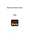
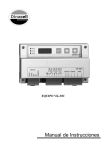
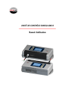
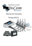
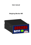
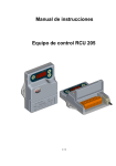
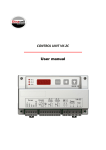
CONTROL UNIT OMEGA 806 User manual User manual OMEGA 806 Series INDEX 1. DESCRIPTION AND MAIN FEATURES ................................................................... 3 2. DISPLAY AND CONTROL BUTTONS ..................................................................... 3 3. INSTALLATION AND CONNECTIONS .................................................................... 4 4. MENU STRUCTURE ................................................................................................. 5 5. HOW TO CHECK OR MODIFY PARAMETERS....................................................... 6 6. SYSTEM CONFIGURATION .................................................................................... 6 7. OPERATIONS DEPENDING ON THE APPLICATION ............................................. 8 7.1. 7.2. 7.3. SYSTEM USED AS A ROPE TENSION MONITOR (WRT)...........................................................9 SYSTEM USED TO WEIGH THE CAR (CWT) OR COUNTERWEIGHT (CTWT) ..................... 10 SYSTEM USED AS A LOAD WEIGHING DEVICE (LWD) ......................................................... 11 8. ADDITIONAL FUNCTIONS .................................................................................... 13 8.1. 8.2. 8.3. HOLD FUNCTION ....................................................................................................................... 13 CHAIN COMPENSATION ........................................................................................................... 13 ANALOG OUTPUT ...................................................................................................................... 14 9. ERROR CODES AND TROUBLESHOOTING ....................................................... 15 10. SPECIFICATIONS .................................................................................................. 15 11. QUICK CONFIGURATION GUIDE ......................................................................... 16 2 User manual OMEGA 806 Series 1. DESCRIPTION AND MAIN FEATURES Dinacell OMEGA 806 is a control unit with several functions: Measuring, monitoring and limiting of the load of a elevator. Monitoring of the tension of each elevator rope individually to its adjustment. Measuring the weight of the elevator car (CWT) or counterweight (CTWT). This system consists of: (a) inputs for up to eight sensors, (b) output for display in the cabin, (c) six relay contacts to inform of the load levels chosen, (d) two analog outputs according with the measured signal of sensors and (e) input to hold function, that inhibit load measure during the elevator travel. 2. DISPLAY AND CONTROL BUTTONS Show alarms status Show load and value of parameters Rope tension monitor Show units Hold function status Control buttons Functions of control buttons: a. Enter/exit of the menu and navigate through parameters. b. Accept and save modified values. a. When load is shown: Enter in the rope tension monitor function b. During menu navigation: Enter to modify a parameter. c. While modifying a parameter: Chose digit to change. a. During menu navigation: Show the stored value of the selected parameter. b. While modifying a parameter: Change the blinking digit incrementally from 0 to 9. 3 User manual OMEGA 806 Series 3. INSTALLATION AND CONNECTIONS Sensors input USB sockets for load cells. (SWK, SWR, TCA, LCA, RTM1, RMT2) Power supply input Earthed 80-260V ac power supply. Analog outputs This output reflects the sensors signal over the range 0-10V or 4-20mA. Common signal is GND. (See the ADDITIONAL FUNCTIONS chapter). HOLD input This function will be activated when an input voltage of 24 to 230V (DC or AC) is applied. (See the ADDITIONAL FUNCTIONS chapter). Relay connections for alarms Terminals of the alarm relays. (See the alarms section in chapter 7.3) 4 User manual OMEGA 806 Series It provides two types of output depending on the CDISP parameter: 1. CDISP = “INCRE”: Progressive display MB-D (two wire connection without polarity). 2. CDISP = “LED”: Under overload it will be an intermittent voltage of 7,5V (max. 75mA) with the polarity shown in the figure. Cabin display output 4. MENU STRUCTURE The menu has the cyclic structure shown in the following figure. Press button for 2 seconds to enter, then press it repeatedly to move from a parameter to another. Press it for 2 seconds to exit. Display the value of the measured load ↓ Sets the sensor type (SWK, SWR, TCA, LCA, RTM1 and RTM2) ↓ Sets the number of sensors to use ↓ Sets measurement units to kg or lb ↓ Sets the elevator ropes diameter (in mm) (Not available when SENSO parameter is set to: TCA, SWR, SWK) ↓ Sets the elevator roping type (1:1 or 2:1) (Not available when SENSO parameter is set to TCA) ↓ Initial reference when sensors are not installed on the ropes (Not available when SENSO parameter is set to TCA) ↓ Parameter to adjust measurement with empty car ↓ Parameter to adjust measurement with car loaded ↓ Sets levels of load that change the relays status ↓ Sets the car display type (incremental or LED) ↓ Sets output type (0-10V or 4-20mA) ↓ Sets the weight of the compensation chain 5 User manual OMEGA 806 Series 5. HOW TO CHECK OR MODIFY PARAMETERS Once inside menu and display showing the parameter to be viewed or changed: Press to check the current value. Press to enter to modify the value: ∙ Press to chose the digit to change (blinking) and (if there’s no digit blinking, change the value with ∙ Press to change it. button directly). twice to save the value. If button is not pressed the second time before display blink ends, the changes will not be stored. After any of these operations, the display shows the current parameter. 6. SYSTEM CONFIGURATION Make sure that the sensors are NOT installed on the ropes 1. Install the control unit with the information of the INSTALL AND CONNECTIONS chapter. 2. Connect sensors to the unit Omega. 3. Power up the unit with the correct voltage (see the SPECIFICATIONS chapter). 2. Set parameter according with the sensors type that it is going to use . 3. Set parameter according with the number of sensors that it is going to be connected. Press 2 sec. to enter Press to enter Choose type of sensor Press to enter Choose number of sensors Press x2 to save value Display shows this Press Press x2 to save value Display shows this 6 User manual OMEGA 806 Series Press Press to enter Choose “kg” or ”lb” Press to enter Select rope diameter (mm) Press x2 to save value Press to enter Select “1:1” or “2:1” Press x2 to save value 4. Set units of measurement. Press x2 to save value Display shows this Press 5. Set diameter of ropes. Display shows this Not available when sensor type is TCA, SWR or SWK. In such case skip this step. Press 6. Set roping type of elevator. Display shows this Not available when sensor type is TCA. In such case skip this step. Press 9. Set with the value “ALL”. Not available when sensor type is TCA. In such case skip this step. Press to enter Choose “ALL” value Press x2 to save value Display shows this The operation sets the zero when sensors are not installed on the ropes. After this, the ropes tension can be measured and adjusted individually as well as the car and counter weight load can be measured. 7 User manual OMEGA 806 Series 7. OPERATIONS DEPENDING ON THE APPLICATION This system has three modes of working: a) can be used to adjust ropes tension (WRT). (See chapter 7.1) b) can be used to measure the weight of the car (CWT) or of the counterweight (CTWT). (See chapter 7.2) c) can be used as a load weighing device (LWD). (See chapter 7.3) Now install sensors on the ropes Install the sensors according with the next drawing depending on the application: Install here to measure the weight of the counterweight Install here: ∙ to measure the weight of the car ∙ to monitor and adjust the tension of the ropes ∙ to use with the elevator interface (as a load weighing device LWD with alarms, analog output, etc.) (Drawing for 1:1 roping) 8 User manual OMEGA 806 Series 7.1. SYSTEM USED AS A ROPE TENSION MONITOR (WRT) ∙ ∙ Make sure the sensors are installed on the ropes. Make sure the cabin is empty and there’s no weight on the car roof. Press repeatedly Press 2 sec. to enter Press to enter 1. Adjust ZERO with the cabin empty. Display shows this Choose countdown seconds Choose Change digit digit Wait countdown Press x2 to start adjustment Press 2 sec. to exit menu 2. Check sensors load individually entering in WRT function. WRT function helps to check tension of all ropes individually. To adjust the tension of the ropes, follow the next step. Press 2 sec. to enter in WRT function Press repeatedly to choose sensor to check Display shows load The sensor chosen is indicated by a circle with its number Press 2 sec. to exit WRT function 4. Adjust tension of ropes with the help of rope tension monitor (WRT) in display, as it is explained with the next figure. Ropes with sensors 1 and 2 are balanced Ropes with sensors 3, 4, 5 and 6 are NOT balanced Sensors 7 and 8 shows not connected 9 User manual OMEGA 806 Series 7.2. SYSTEM USED TO WEIGH THE CAR (CWT) OR COUNTERWEIGHT (CTWT) ∙ ∙ Make sure the sensors are installed on the ropes. Make sure the cabin is empty and there’s no weight on the car roof. Press 2 sec. to enter Adjust ZERO with the cabin empty. Press repeatedly Press to enter Display shows this Choose countdown seconds Choose Change digit digit Wait countdown Press x2 to start adjustment Now, after ZERO setting, the measured value of the Car Weight (CWT) or Counterweight (CTWT) can be checked (depending on where the sensors were installed). Keep pressed the button during 2 seconds and the weight will be shown in display. This value remains stored despite the sensors are uninstalled from the ropes. The system is factory calibrated, nevertheless, if it is considered that there is a high friction on the guides of the elevator, in order to optimize results on the measurement, an additional operation could be done using a well known weight inside the cabin. ∙ ∙ Make sure that zero adjustment is already done Introduce inside the cabin a well known weight (minimum 50% of the elevator full load). Press 2 sec. to enter Press repeatedly Press to enter Display shows this Enter the value of the real weight inside the cabin Choose Change digit digit Wait countdown Press x2 to start adjustment 10 User manual OMEGA 806 Series 7.3. SYSTEM USED AS A LOAD WEIGHING DEVICE (LWD) ∙ ∙ Make sure the sensors are installed on the ropes. Make sure the cabin is empty and there’s no weight on the car roof. 1. Drive the elevator car to the middle of the shaft. 2. Bounce in cabin to insure there’s no friction on guides. Press repeatedly Press 2 sec. to enter Press to enter 3. Adjust ZERO with the cabin empty. Display shows this Choose countdown seconds Choose Change digit digit Wait countdown Press x2 to start adjustment Introduce inside the cabin a well-known weight (minimum 50% of the elevator full load). Press Press to enter 5. Adjust LOAD with the cabin loaded. Display shows this Enter the value of the real weight inside the cabin Choose Change digit digit Wait countdown Press x2 to start adjustment 11 User manual OMEGA 806 Series Press to enter in alarms submenu Press 6. Set alarms. “Alarms” are the programmed load levels that change the state of relays. (It is not necessary to introduce weight in the cabin). Display shows this Choose alarm Enter to Keep modify pressed to check value Press x2 to save Enter the level Choose relay contacts “open” or ”close” Alarm 1 2 Relay 1 2 3 3 4 5 6 4 5 6 Press 2 sec. to exit Choose Change digit digit RELAYS ASSIGNMENT Function Relay for Full Load. Relay for Overload. Relay for Unlevel Wire Rope Tension Fixed assignment: This function cannot be configured in a different alarm relay. Additional relays to activate MB-D, LED, buzzer or other warning devices. Press 7. Set cabin display output. Press x2 to validate Press Select to enter “INCRE” or ”LED” Press x2 to save value Display shows this Press once to go to the CHAIN parameter. (See the ADDITIONAL FUNCTIONS chapter). 12 User manual OMEGA 806 Series 8. ADDITIONAL FUNCTIONS 8.1. HOLD FUNCTION When a voltage in the range 24-230V (DC or AC) is applied in this input, the unit stops to measure and the last value of weight acquired will be shown in display. The voltage must be applied when the doors close and the it must be removed when the doors open. This ensures that the movement of the cabin will not affect the weighing process and therefore, no relay will be activated during elevator travel. Also, when the doors are closed, since no more people will be entering in the cabin, there is no reason to continue the weighing process. When the doors open, voltage must be removed from the hold input so that the unit can begin measuring the load in the cabin. 8.2. CHAIN COMPENSATION This function allows to compensate the difference of weight between floors produced by the compensation chain. The unit needs the HOLD signal active when the doors close to compensate the weight during the elevator movement. How to set the chain compensation weight (Max. 200 kg): Press 3 sec. to enter Press repeatedly Press to enter Display shows this Press 3 sec. to exit Enter the value of the weight of compensation chain (Max 200kg). Choose Change digit digit Press x2 to start adjustment The default value is zero (00000), this means that no chain compensation is activated. 13 User manual OMEGA 806 Series 8.3. ANALOG OUTPUT The unit is provided with two analog outputs (0-10V and 4-20mA) selectable with the parameter : Press repeatedly Press 3 sec. to enter Select “u0_10” Or ”I4_20” Press to enter Press x2 to save value Display shows this Press 3 sec. to exit This function reflects the sensors signal over the range between ZERO and the value sets for ALARM1 (full load): Parameter u0_10 I4_20 Mode 0-10 volts 4-20 mA Range When weight ≤ 0kg (empty elevator) When weight ≥ ALARM1 (elevator at full load) When weight ≤ 0kg (empty elevator) When weight ≥ ALARM1 (elevator at full load) 0V 10 V 4 mA 20 mA Example: Once that the system is completely configured, if ALARM1 is set to 400 kg., when the unit is measuring 200kg. The analog output will be 5V in mode 010V and it will be 12mA in mode 4-20mA. 14 User manual OMEGA 806 Series 9. ERROR CODES AND TROUBLESHOOTING When the unit detects some anomaly it will show an error codes of the following: Important: When an error appears, all alarms are activated and the elevator remains blocked. Error description Load cell is not properly connected, it or its cable is damaged. Negative overflow. The load cell is giving a negative signal too high. Positive overflow. Load cell is holding a higher load than its nominal value. Polarity error. This happens when the unit adjusts the weight with the wrong load cell polarity, or the weight is not in the cabin during the adjustment. Loss of data in memory. Notice: When this error appears, every relay will remain in OFF state. Load cell with very low sensibility. Usually the unit is wrong adjusted. Action Check the load cells connection. Check the load cell connection because it should be no negative charge. load cell by another with higher nominal load. Check the load cells connection. Adjust the zero and weight again. The unit must be configured again with the properly values. Adjust the zero and weight again. RESTORING THE FACTORY SETTINGS (Only in case of configuration problems) Press Press repeatedly simultaneously to find “RESET” Enter Choose “YES” Press x2 to save value Press 2 sec. to exit 10. SPECIFICATIONS Power supply characteristics Nominal voltage Maximum current Nominal frequency Relays Contacts Box Short-circuitable. It is not necessary to replace any fuse. 80-260V ac 130mA 50-60 Hz Normally Open 250V – 3A IP-50 V0 fireproof plastic. 15 User manual OMEGA 806 Series 11. QUICK CONFIGURATION GUIDE Parameters checking or modification Press 2 sec. to enter Press repeatedly to find the desired parameter Press 2 sec. to exit Modify the value Check Enter to value modify Change Choose digit digit Press x2 to save value System configuration 1. Make the necessary connections. 2. Make sure that the sensors are not installed on the ropes. 3. Set parameter according with the sensors type. 4. Set parameter according with the number of sensors. 5. Set of measurement (“kg” or ”lb”). Next three parameters are available depending on the type of sensor selected. 6. Set according with the type of ropes of the elevator. 7. Set according with the roping type of the elevator. 8. Set with the value “ALL”. 9. NOW, install sensors on the ropes as shown in drawing of the chapter 7 depending on the application 10. Adjust ZERO with the cabin empty. Follow next operations “a” or “b” depending on the application: a) Operations when system is working as a rope tension monitor (WRT) 1. Check sensors load individually pressing button during 3 seconds and then exit pressing button during 3 seconds. 2. Adjust tension of ropes with the help of rope tension monitor (WRT) in display. b) Configuration when system is working as load weighing device (LWD) 1. After ZERO adjustment: adjust LOAD with a well-known weight inside the cabin. 2. Set desired alarms levels. 3. Set cabin display output (“INCRE” for progressive display or “LED”). 4. Set the chain compensation weight (max. 200 kg). Dinacell Electrónica, S.L. - www.dinacell.com C/ El torno, 8 - 28522 Rivas Vaciamadrid - Madrid (SPAIN) Tel.: +34 91 300 14 35 – Fax: +34 91 300 16 55 92-4464-02 07/06/2012 16