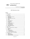
1
STAR Receiver Generation 2 For Audio Networks User’s Guide Revision 1.1 STAR Gen 2 Receiver User’s Guide Table of Contents SAFETY WARNINGS ................................................................................................................................ 3 GETTING STARTED ................................................................................................................................. 4 Models .................................................................................................................................................. 4 How to Use This Guide ........................................................................................................................ 4 QUICK START ........................................................................................................................................... 4 What You Should Have Received ........................................................................................................ 4 The Front Panel .................................................................................................................................... 4 The Rear Panels – STAR-Four & STAR-Two ...................................................................................... 5 Default Settings .................................................................................................................................... 6 First Installation and Configuration of the STAR ............................................................................... 6 ADVANCED TOPICS ................................................................................................................................ 8 Remote Control with a WEB Browser .................................................................................................. 8 The Menu Bar ....................................................................................................................................... 8 Identity .................................................................................................................................................... 8 Input ........................................................................................................................................................ 9 SAT-IN ............................................................................................................................................... 9 IP-IN................................................................................................................................................. 10 DVB-TS ................................................................................................................................................. 10 Decoder ................................................................................................................................................ 11 Decoder Audio ................................................................................................................................. 11 Decoder Backup Channel x ............................................................................................................. 13 Decoder Data .................................................................................................................................. 13 Control .................................................................................................................................................. 14 Control MGMT IP ............................................................................................................................. 14 Control MGMT Notification Mode .................................................................................................... 15 Control MGMT Notification Priority .................................................................................................. 16 Control MGMT Notification Destination ........................................................................................... 16 Control I/O ....................................................................................................................................... 16 Control XD ....................................................................................................................................... 16 Alarm ............................................................................................................................................... 17 Alarm Menus and Sub Menus ......................................................................................................... 17 Status ................................................................................................................................................... 18 Utility .................................................................................................................................................... 22 Logout .................................................................................................................................................. 25 GUI TIPS .................................................................................................................................................. 26 Finding extra Help .............................................................................................................................. 26 Drop down Menus .............................................................................................................................. 26 Valid numeric Ranges ........................................................................................................................ 26 Text in Red ......................................................................................................................................... 26 REMOTE CONTROL BY SNMP.............................................................................................................. 27 CONNECTOR SPECIFICATIONS ........................................................................................................... 28 KEYPAD CONTROL ............................................................................................................................... 29 Measurement Displays ....................................................................................................................... 29 Settings Menu Flowchart .................................................................................................................... 30 WEEE DISPOSAL INSTRUCTIONS ....................................................................................................... 37 WARRANTY & SERVICE INFORMATION ............................................................................................. 38 Page 2 of 39 STAR Gen 2 Receiver User’s Guide Safety Warnings THE UNIT MUST BE INSTALLED BY A QUALIFIED SERVICE PERSON AND THE EXTERNAL EARTH CONNECTION MUST BE MADE BEFORE CONNECTING THE AC SUPPLY. USE A GROUNDED POWER OUTLET ONLY. AN ANTI-SHOCK DEVICE MUST BE INSTALLED ON THE ANTENNA CABLE CONNECTING TO THE UNIT. THE UNIT MUST BE GROUNDED AT THE REAR PANEL GROUND CONNECTION. DO NOT OPERATE THE UNIT IN DIRECT SUNLIGHT, A DUSTY OR DAMP ENVIRONMENT AND DO NOT BLOCK THE VENTILATION HOLES. THE UNIT IS DESIGNED TO OPERATE IN A TEMPERATURE RANGE OF 0ºC TO 40ºC. THE POWER RATING AND HEAT GENERATION OF THE UNIT ARE SUCH THAT IT CAN BE PLACED IN A 19” CABINET WITHOUT SPECIAL COOLING FACILITIES. HOWEVER, SUFFICIENT CLEARANCE MUST BE MAINTAINED BETWEEN THE UNIT AND OTHER EQUIPMENT (A 1RU GAP). DO NOT OPEN THE UNIT FOR ANY REASON. WARRANTY. THIS IS DANGEROUS AND MAY VOID YOUR IF THE UNIT FAILS TO OPERATE CALL YOUR SERVICE PROVIDER CUSTOMER SUPPORT. THE STAR IS A 19” 1U RACK-MOUNTING UNIT WITH CONNECTOR ACCESS AT THE REAR. THE UNIT CAN BE MOUNTED AT THE FRONT OF A 19” RACK USING AN APPROPRIATE MOUNTING SET. HOWEVER, THE USE OF LATERAL SUPPORT IS STRONGLY RECOMMENDED. Page 3 of 39 STAR Gen 2 Receiver User’s Guide Getting Started International Datacasting Corporation (IDC) would like to thank you for purchasing this STAR Generation 2 receiver (herein referred to as the “receiver”). This User’s Guide provides step by step instructions on how to connect the receiver, access satellite services, and set system and audio output configurations. Models Your STAR Generation 2 receiver is one of a family of STAR receivers. A datasheet at the end of this document provides the Technical Specifications of your STAR receiver. Readers of this manual who use a STAR-Two receiver should ignore any references to audio 3 & 4, decoder 3 & 4 or channel 3 & 4. How to Use This Guide This guide describes the operation of your receiver through the GUI. There is also a reference describing operation with the keypad interface. Within the document you will find: o a Quick Start section about connecting to the receiver and what the displays mean. o an Advanced Topics section explaining how to use the GUI interface to configure the receiver and enable the outputs. o a GUI Tips section explaining extra information and on-screen choices. o a Keypad Control section for local control of your receiver. Quick Start If you have installed IDC products before, you can skip this section. If not, you will be familiarized with the status and controls of the STAR receiver prior to being shown how to find the receivers IP Address and how to connect to it through the GUI to configure the receiver for use. What You Should Have Received You should have received the following package: o One (1) STAR Generation 2 Receiver; o One (1) power cord, suitable for use in your country; o One (1) copy of this User’s Guide – also available online from the IDC Customer Service FTP site. You will need audio cables to connect the receiver to your system. Please keep one set of packaging that your receiver came in, to allow for a safe return for repair if required. The Front Panel The STAR front panel contains nine LED indicators, a headphones jack and a keypad LCD combination. 1 2 3 4 Page 4 of 39 STAR [1] Headphones [2] Status information: STAR-Four Gen 2 Receiver User’s Guide STAR-Two The status information of the receiver is shown in the LEDs as described in the table below. A blank cell shows an unused status/colour combination. LED status indication Indication OFF LOCK Unit disconnected Locked to carrier or power failure WARNING No warning ALARM No alarm AUDIO 1/2 No service Audio OK / Playing local file PID/MPE-IP or audio error REMOTE No M & C link Link connected remotely Local control; link available AUDIO 3/4 No service Audio OK / Playing local file PID/MPE-IP or audio error OPTION Future Use RECORD Future Use [3] GREEN / Flashing Green RED YELLOW Not locked to carrier Warning Alarm LCD The LCD display is used to view receiver status, view receiver configurations and/or set receiver configurations. How to access these settings is described in the section Keypad Control. [4] Keyboard Scroll buttons (4) Select button Cancel button The Rear Panels – STAR-Four & STAR-Two 1 2 3 4 5A 5B 5C 5D 7 6 9 8 10 11 12 Page 5 of 39 STAR [1] Grounding [2] Mains AC 100-240v built in fuse 2.5A [3] Alarm contacts (3) [4] Audio In (Future use) [5] Audio Channels & Relays 1, 2, 3 & 4 [6] ASI In [Factory installed option] [7] Data LAN [8] RS232 Comm port [9] Monitor & Control LAN [10] L-band input and loopthrough [11] SD card slot [12] Recovery reset Gen 2 Receiver User’s Guide Default Settings Your STAR receiver is supplied with these default settings: 1. Control mode is: remote 2. IP mode is: DHCP First Installation and Configuration of the STAR 1. Connect power to the power inlet without connecting the L-band cable to your STAR receiver. The front panel LCD will show “Superflex PA Booting OS”. The LEDs on the front panel show (on the left): 2. After a few seconds all LEDs flash once and the LCD screen will display “Initializing”. When initialization is complete after a few seconds, the LEDs show (on the right), with no external connections: INDICATIONS LOCK WARNING ALARM AUDIO 1 AUDIO 2 REMOTE AUDIO 3 /OPTION 1 AUDIO 4 /OPTION 2 RECORD COLOR NONE YELLOW RED NONE NONE NONE NONE NONE NONE NONE NONE INDICATIONS LOCK WARNING ALARM AUDIO 1 AUDIO 2 REMOTE AUDIO 3 /OPTION 1 AUDIO 4 /OPTION 2 RECORD COLOR RED RED RED RED RED NONE RED RED NONE NONE NONE Page 6 of 39 STAR Gen 2 Receiver User’s Guide 3. Connect the STAR to a DHCP IP network. The IP address that is assigned to the STAR can be read in the front panel LCD menu “MGMT->IP-ADDR=” (select this parameter using the keypad). If a DHCP network is not available we recommend that you connect the STAR with a switch or computer; the STAR will generate a random IP address. Read the address in the LCD screen “MGMT->IP-ADDR=” and set your computer IP address in the same range. You can also use the LCD to configure a static IP address (Control>MGMT> IP Static Address) if DHCP in not available on your network. 4. Connect a personal computer to the receiver, open a web browser and connect to the receiver by typing the IP address of the receiver in your browsers address bar. 5. Login with: Username: admin. Password: 12345. You can change the login username and password with the web GUI in the “CONTROL” menu. Your STAR receiver is now ready for use. Page 7 of 39 STAR Gen 2 Receiver User’s Guide Advanced Topics The receiver can be configured through the Graphical User Interface or from the front panel Keypad. Remote Control with a WEB Browser When you have logged in, you will see the Web Configuration Manager page. Device name, Device type, Serial number, Firmware version and activated Options. Link to an online Manual. Define the link in the “IDENTITY” menu. See next page. Menu bar (see below for details). Monitoring Status & Routing. Warning, alarms indicator. Time, Date, Synchronization with SNTP server. The Menu Bar There are 8 top level menus and a logout button in the menu bar presented here in order left to right. Identity In the Identity page you can fill in specific information that will be visible on the Welcome page and you can also include a link that points to a manual. Page 8 of 39 STAR Gen 2 Receiver User’s Guide DEVICE NAME, DEVICE LOCATION, DEVICE CONTACT, and DEVICE INFO 1-12: enter additional information which will be visible at the WELCOME page of the WEB GUI. This information can be a link to another website. DEVICE MANUAL LINK: this link to a server can be defined to point to a manual. The link button MANUAL will be found on the menu bar when a link is defined. Link Examples are: file://///server/share/path, ftp://server/file, ftps://server/file, http://sitelink, https://sitelink. Input There are 2 input sources: SAT-IN (which is a satellite L-Band signal) and IP-IN (a Transport Stream over IP input). A factory installed optional ASI input is also available. SAT-IN Different types of outdoor LNBs are supported. For easy setup, the Local Oscillator (LO) frequency can be entered. However, when the STAR receiver is used with Netmanager control the LO frequency needs to be set to 0 KHz, and all receiver frequencies need to be entered in the L-band range only. NCC = Network Control Channel, which contains the network control data generated by IDC’s Netmanager2. Polarization in the Carrier definition menu’s are only available when the LNB mode is set to “Universal”. The preferred carrier setting is useful when a transition to a carrier is needed. This function is also supported and controlled by NCC. If only one Carrier setting is required the Prefered can be set to “Carrier A (or B) only”. The options to set the other carrier will be removed from the receivers interface when “Carrier A (or B) only” is selected. This feature is not controlled by NCC. Page 9 of 39 STAR Gen 2 Receiver User’s Guide IP-IN LOCAL PORT Mode: Select between AUTO (up to 1Gbit) or 100 Mbit (Half or Full duplex). LOCAL PORT IP Address: This is the IP Address in the LAN network. INPUT STREAM IP Address/UDP Port: This is the IP Address/Port number on which the MPEG2 TSoverIP stream is received. DVB-TS INPUT: Decoder input can be selected between SAT IN (L-band tuner) or IP IN (TSoIP). PID LIST: This allows you to enter and enable MPE PIDs that are required to decode IP Audio services. DVB-TS FLEXKEY: (Optional) This setting is needed to identify the IP address and port number which contains the ECM messages sent by Flexkey Encryptor. Page 10 of 39 STAR Gen 2 Receiver User’s Guide Decoder Decoder Audio Page 11 of 39 STAR Gen 2 Receiver User’s Guide CHANNEL x Audio: STREAM: when stream is set to MPE then select from: MODE: OFF, CHAN.GUIDE, MPE, TONE. Note: If Channel Guide mode is selected, the receiver will populate the service list automatically. The channel information is provided by the SDP packets from the Event Managers at the headend. The MPE PID for the SDP packets must be added to the receiver PID list to get the list of Services. The Channel Guide is the list of programs you can select in MPE mode. The user selects the wanted service, and the unit will select the appropriate IP address and PORT number. In MPE mode this address and port has to be done manually. Note: If tone is selected, the receiver outputs a 1Khz note. STREAM: when stream is set to PES then select from: MODE: OFF, PSI, PID, TONE. Note: In PSI mode the receiver will populate its service list from the PSI table in the DVB carrier. The user selects the wanted service, and the unit will select the appropriate PID. In PID mode this PID has to be set manually. Note: If tone is selected, the receiver outputs a 1Khz note. SERVICE: shows the list of services available. When there is no list, “SIGNAL?” will be shown. 15 kHz LOWPASS: ON/OFF. Enabling the low pass filter limits the upper frequency range to 15Khz with a 3db/octave attenuation. GAIN: Set the gain from -18 to +18 dB, in steps of 1 dB. STEREO/MONO: Select Stereo (Dual), Mono L+R, Mono L, Mono R. DELAY: Input presentation delay from 0 to 8000 milliseconds. OPTIONAL (not shown): LIMITER ENABLED: ON/OFF. LIMITER LEVEL: -50 to 0 dBFS, in steps of 1 dB. LIMITER RECOVERY: 20 (Fast) to 100 (Slow) Milliseconds recovery time. Page 12 of 39 STAR Gen 2 Receiver User’s Guide Decoder Backup Channel x The backup for each audio channel can be enabled/disabled and the order of choice for the backup source can be defined. Additionally each backup source can be viewed and or configured. As delivered, there are no audio backup files on the SD card. Multiple audio files (.mp2 or .mp3) can be stored in the SD card root directory, but only one can be identified as the default file. If the Service Operator has delivered a backup playlist, this will be played instead of the default file (If enabled). Consult the Service Operator for full details. Decoder Data CHANNEL x Data: STREAM: when stream = MPE (in menu DECODER/AUDIO) then: MODE: OFF, ANC. DATA, ASYNC. DATA. Note: ANC. DATA is data transport in the ancillary field of coded audio. ASYNC. DATA is data transport in the MPE RTP header of audio stream. STREAM: when stream = PES (in menu DECODER/AUDIO) then: MODE: OFF, ANC. DATA, PRIV. DATA. Note: ANC. DATA is data transport in the ancillary field of coded audio. PRIV. DATA is data transport in a separate PID of the transport stream. PROCESS: MUX, OFF. BAUD: Output baud rate of the Anc/Async data: 1200, 2400, 4800, 9600, 19k2, 38k4, 57k6 baud. Page 13 of 39 STAR Gen 2 Receiver User’s Guide Control Control MGMT IP Choose the parameters to configure the network connections, utilize SNMP, specify the NTP server, configure the web access and change the username/password combination. MODE: DCHP, MANUAL Note: In DCHP mode Static Address, Subnet Mask and Gateway Address are not available. Page 14 of 39 STAR Gen 2 Receiver User’s Guide Control MGMT Notification Mode Choose the parameter (ALL; HEARTBEAT; SETTING CHANGED; CONTROL MODE CHANGED; CONTROL MODE LOCAL SUPPRESS) that produces a notification and the type of that notification (OFF; WARNING; WARNING+ALARM) to the SNMP trap set under Control>MGMT>Notification>Destination. Page 15 of 39 STAR Gen 2 Receiver User’s Guide Control MGMT Notification Priority Select the priority for the notifcation of an alarm in a parameter. Each parameter shown on the Control MGMT Notification Mode Alarm Mode list can be assigned a priority between 1 and 4294967295 with 1 being the highest priority. The default value is 0 and indicates No Priority. Control MGMT Notification Destination Enable/Disable notifications to the chosen SNMP destinations. Control I/O This will allow operators to view and change the status of the contacts manually for testing. Please note that Decoder Data Process needs to be switched to OFF. (Support depends on the device configuration). Control XD View and enter the PID, IP address and corresponding port for each of the XD packet streams received by your Star receiver. Page 16 of 39 STAR Gen 2 Receiver User’s Guide Alarm The following settings are available in the ALARM submenus: : OFF : Warning Only MODE : Warning+RelayA : Warning+RelayB : Warning+RelayC = Warning and Alarm are switched off. = Upon an error condition the Warning light on the front will be activated. = Upon an error condition, after the warning delay period has passed, the Warning light on the front panel will illuminate. It will remain illuminated until the alarm delay period has passed, at which point the Warning LED will turn off, the Alarm Led will flash red and relay A will become active. = Upon an error condition, after the warning delay period has passed, the Warning light on the front panel will illuminate. It will remain illuminated until the alarm delay period has passed, at which point the Warning LED will turn off, the Alarm Led will flash red and relay B will become active. = Upon an error condition after the warning delay period has passed, the Warning light on the front panel will illuminate. It will remain illuminated until the alarm delay period has passed, at which point the Warning LED will turn off, the Alarm Led will flash red and relay C will become active. LEVEL = Not present for all parameters. When present it is programmable between the limits revealed when you hover your mouse over the Level field. W- DELAY = Delay in seconds before the warning light will be activated. A- DELAY = Delay in seconds before the alarm light and relay will be activated. Note: to receive an alarm on the relay outputs, the alarms must be properly configured. 1. Warning Delay (W-DELAY) is programmable between 0 and 599 seconds. 2. Alarm Delay (A-DELAY) is programmable between 1 and 600 seconds. The warning-delay should always be less than the alarm-delay. When the warning-delay is entered higher than the alarm-delay, the alarm-delay will automatically be set to the warning-delay-time + 1 second. Alarm Menus and Sub Menus Shows information about and allows setting of the alarms for input and audio levels including backup and data. The alarm information can also be printed. Two sub-menus with multiple sub-menus contain the information: INPUT: the Satellite or IP IN parameters. DECODER: the PSI, Audio, Backup and Data parameters for all channels. Page 17 of 39 STAR Gen 2 Receiver User’s Guide The Alarm mode contains multiple pull down menus for selection. In the EDIT mode, each selected item (MODE, LEVEL, WARNING DELAY and ALARM DELAY) can be independently set (see examples below): Hover over a field underlined “…………” to see the valid range. With the mouse cursor in the editable field, an information field will pop up with the value limits: Status Information about the input and audio levels and the status information can also be printed. Five submenus contain the information: INPUT: the Satellite RF-IN and IP IN parameters: Page 18 of 39 STAR Gen 2 Receiver User’s Guide Page 19 of 39 STAR Gen 2 Receiver User’s Guide DECODER: the source indication with Transport Stream info, four channels of audio with the left/right dynamic level and the selected service. Transport Stream and RTP/IP audio show their respective data rates if used as the input. The contact closures show the relay status as “C” closed or “O” for open. Page 20 of 39 STAR Gen 2 Receiver User’s Guide NETMANAGER: indicates if the receiver is connected to a Network Command Channel (NCC) and the date and time when this receiver last accepted a valid set of NCC-commands: SDCARD: this menu will show if a valid SD Card has been detected. It will also display if valid audio files, which can be used for backup purposes, are found: Page 21 of 39 STAR Gen 2 Receiver User’s Guide DEVICE CONFIG: shows all device specific information: Utility There are 9 submenus: CLOCK, CLEAR LOG, PRINT SETTINGS, DEFAULT SETTINGS, IMPORT/EXPORT, TRIGGER, INSTALL OPTIONS, UPDATE FIRMWARE & REBOOT DEVICE. CLOCK: The unit clock can be switched on. The clock is synchronized with the NTP server. The IP address for the NTP server can be configured in the menu CONTROL MGMT IP. Page 22 of 39 STAR Gen 2 Receiver User’s CLEAR LOG: The log file can be cleared. PRINT SETTINGS: The complete settings of the unit can be printed in one overview. DEFAULT SETTINGS: The default settings can be loaded. Guide Warning: Loading default settings reboots the receiver resulting in IP service downtime. The settings of the LINK, TCP/IP and NAME group of CONTROL IP TCP/IP will not be reset to the default value in order to be able to reconnect to the device again. IMPORT/EXPORT: All settings of this unit can be exported in a file (binary format) to a selectable location and a user editable filename. The same settings file can be imported as well, to make an easy copy possible. When imported, a tickbox can be selected to choose if the IP settings and Identity have to be excluded. TRIGGER: A decoder or All Decoders can be selected. A full list of all utility triggers can be viewed from the All Decoders page or by using the View the full List for ALL decoders radio button on any decoder trigger page. No triggers can be fired from the full list page; triggers can be selected from a list of available triggers loaded by the head end and fired on the specific decoder page only. Page 23 of 39 STAR Gen 2 Receiver User’s Guide If a trigger is missing one or more content files it is highlighted in red. Selecting the trigger and clicking “Show Details” reveals which file (or files) is missing. If this trigger is fired, the missing file will be skipped over, regardless of its position in the Playlist. The details of a particular trigger can be viewed by selecting the trigger and clicking the “Show Details” button. Each field is explained below: EARLIEST VALID: The earliest date on which the action becomes valid. EXPIRY: The latest date on which this action may be commenced. May show “Does not expire”. FADE (TYPE ,TIME): The type and duration of the fading used (X-fade, V-fade or ½ fade). REPEAT: If this trigger is to be repeated. RECURRENCE: The days of the week within the Earliest Valid up to the Expiry date on which this action will be valid. Page 24 of 39 STAR Gen 2 Receiver User’s Guide START METHOD: How the action is commenced. ELEM ID: Internally allocated reference. ACTION: What the receiver will do when the action is triggered. INSTALL OPTIONS: In this section all options can be activated or de-activated with code of from an .xml file. UPDATE FIRMWARE: Firmware can be uploaded from any accessible location and will result in service downtime. REBOOT DEVICE: This will trigger a reboot of the device, which will result in a service downtime. The unit will start up again with the last saved settings. Logout You will be asked to confirm your log out. Page 25 of 39 STAR Gen 2 Receiver User’s Guide GUI Tips Finding extra Help On many Web pages, hovering your mouse pointer over the information button information related to the parameter: will produce extra Drop down Menus In several menus, drop down sub-menus are available to help in selecting a value. Valid numeric Ranges In other cases a value can be set in an edit field shown as “…………………….” (the valid range is shown if you hover over the field with the mouse pointer). Text in Red When saving a change, if the GUI refreshes with the change shown in red the changes were not made. An explanation bar will appear with specific details of the error. Page 26 of 39 STAR Gen 2 Receiver User’s Guide Remote control by SNMP SNMP is the abbreviation for “Simple Network Management Protocol”. It is connected over the Monitor & Control LAN connector at the rear of the unit. To have a list of all functions supported in this device, a MIB file is available on request. Remote control is based upon different types of messages: GET, SET, TRAPS, INFORMS etc. To define further communication between the STAR and other SNMP devices/applications, a package with MIB files is made available on request. Included in the MIB package is an application note describing all available settings. Please note that all SNMP connection related settings are available in the CONTROL/MGMT/IP and CONTROL/MGMT/NOTIFICATION menus. The STAR supports SNMP v1 TRAPS, SNMP v2c TRAPS and SNMP v2c INFORMS. STAR default community names are: GET=”usr_read_access” SET=”usr_write_access” The community names are configurable in the CONTROL>MGMT>NOTIFICATION>DESTINATION menu. Page 27 of 39 STAR Gen 2 Receiver User’s Guide Connector Specifications Alarm output connector 9-pole Sub-D female connector Pin Description 1 Relay A common 2 Relay A normally open 3 Relay B normally closed 4 Relay C common 5 Relay C normally open 6 Relay A normally closed 7 Relay B common 8 Relay B normally open 9 Relay C normally closed Audio output connector (per channel) 9-pole Sub-D male connector Pin Description 1 Analog Left Out + 2 Analog Ground 3 AES + 4 Analog Ground 5 Analog Right Out + 6 Analog Left Out 7 Analog Ground 8 AES 9 Analog Right Out - RS232 comm connector 9-pole Sub-D female connector Pin Description 1 DCD 2 RX (In) 3 TX (Out 5 DTR 6 Ground 7 RTS 8 CTS 9 RI “Normally closed” is the switch status when AC power is not connected, or when power is connected and the alarm status is activated. Relay connector (per channel) 15-pole male connector Pin Description 1 Reserved (future RS-232 Data out) 2 Relay 1 NO 3 Relay 2 NO 4 Relay 3 NO 5 Relay 4 NO 6 Ground 7 Relay 5 NO 8 Relay 6 NO 9 TX data Out (RS-232 Data Out) 10 Common 11 Common 12 Relay 7 NO 13 Relay 8 NO 14 Relay 9 NO 15 Relay 10 NO Page 28 of 39 STAR Gen 2 Receiver User’s Guide Keypad Control Measurement Displays Press the ◄/► keys to navigate through these measurement displays: Superflex PA Booting OS... Initializing... C/N(dB) EbNo(dB) 13,5 13,2 PWR(dBm) BER -62 <1.0E-7 FE(kHz) CARRIER -67 A MGMT IP Address 10.0.1.14 CH1[audio vu bar -30 -9 -3 0 CH2[audio vu bar -30 -9 -3 0 CH3[audio vu bar -30 -9 -3 0 CH4[audio vu bar -30 -9 -3 0 CH1 CH2 CH3 CH4 [▄ ][▄ ][▄ ][▄ ] NCC NO LAST UPD NO SYNC Press the ▲/▼ (up down) or enter key to show the Settings menu display mode. Page 29 of 39 STAR Gen 2 Receiver User’s Guide Settings Menu Flowchart Grey shows Optional or Special Order Item 1 IDENTITY Control Mode LOCAL / REMOTE Device Type STAR G2 Version V002 Serial XXXX Mgmt LAN MAC Data LAN MAC 2 INPUT 2.1 SAT-IN 2.1.1 LNB Mode L-Freq (MHz) 2.1.2 RF-IN Preferred 2.1.3 CARRIER A 2.1.4 CARRIER B Frequency (kHz) Mode Rate (sym/s) NCC PID 2.2 IP-IN 2.2.1 LOCAL PORT Mode IP Address MAC Address 2.2.2 INPUT STRE IP Address UDP Port 2.3 ASI-IN 3 DVB-TS 3.1 STREAM Input 3.2 PID LIST 3.2.1 PID1 SAT-IN / IP-IN 3.2.2 PID2 3.2.3 PID3 3.2.4 PID4 3.2.5 PID5 3.2.6 PID6 3.2.7 PID7 3.2.8 PID8 Mode MPE PID Page 30 of 39 STAR 3.3 FLEXKEY Gen 2 Receiver User’s Guide IP Address UDP Port 4 DECODER 4.1 AUDIO 4.1.1 CHANNEL 1 4.1.2 CHANNEL 2 4.1.3 CHANNEL 3 4.1.4 CHANNEL 4 Stream Mode Service 15KHz Lowpass Gain Stereo/Mono Delay Limiter 4.2 BACKUP 4.2.1 CHANNEL 1 4.2.2 CHANNEL 2 4.2.3 CHANNEL 3 4.2.4 CHANNEL 4 Enabled Priority 4.3 DATA 4.3.1 CHANNEL 1A 4.3.2 CHANNEL 1B 4.3.3 CHANNEL 2A 4.3.4 CHANNEL 2B 4.3.5 CHANNEL 3A 4.3.6 CHANNEL 3B 4.3.7 CHANNEL 4A 4.3.8 CHANNEL 4B Mode Format (Process)/Baud Process only in PES mode 6 CONTROL 6.1 MGMT IP Mode IP Link IP Static Addr. IP Subnet Mask IP Gateway WEB Enabled SNMP Enabled 6.2 IO 6.2.1 CHANNEL 1 6.2.2 CHANNEL 2 Page 31 of 39 STAR Gen 2 Receiver User’s Guide 6.2.3 CHANNEL 3 6.2.4 CHANNEL 4 CONTACT 1 CONTACT 2 CONTACT 3 CONTACT 4 CONTACT 5 CONTACT 6 CONTACT 7 CONTACT 8 CONTACT 9 CONTACT 10 7 ALARM 7.1 INPUT 7.1.1 SAT-IN 7.1.1.1 RF-Lock Mode Warning Delay(s) Alarm Delay (s) 7.1.1.2 POWER Mode Level (dBm) Warning Delay(s) Alarm Delay (s) If BER alarm 7.1.1.3 BER Mode is set active, Level Mantissa all audio will Level Exponent be muted. Warning Delay(s) Alarm Delay (s) 7.1.1.4 C/N Mode Level (dB) Warning Delay(s) Alarm Delay (s) 7.1.1.5 Eb/No Mode Level (dB) Warning Delay(s) Alarm Delay (s) 7.1.1.6 TS Mode Warning Delay(s) Alarm Delay (s) Page 32 of 39 STAR 7.1.2 IP-IN Gen 2 Receiver User’s Guide Mode Warning Delay(s) Alarm Delay (s) 7.2 DECODER 7.2.1 PSI Mode Warning Delay(s) Alarm Delay (s) MODE; WARNING DELAY & ALARM DELAY are settable for 7.2.2 Audio, 7.2.3 Backup and 7.2.4 Data items. LEVEL is also settable for Audio LEFT, RIGHT and L+R 7.2.2 AUDIO 7.2.2.1 CH 1 7.2.2.2 CH 2 7.2.2.3 CH 3 7.2.2.4 CH 4 7.2.2.4.1 LEFT 7.2.2.4.2 RIGHT 7.2.2.4.3 L+R 7.2.2.4.4 STREAM 7.2.3 BACKUP 7.2.3.1 CH 1 7.2.3.2 CH 2 7.2.3.3 CH 3 7.2.3.4 CH 4 7.2.3.4.1 MPEGTS 7.2.3.4.2 RTP/IP 7.2.4 DATA 7.2.4.1 CH 1A 7.2.4.2 CH 1B 7.2.4.3 CH 2A 7.2.4.4 CH 2B 7.2.4.5 CH 3A 7.2.4.6 CH 3A 7.2.4.7 CH 4A 7.2.4.8 CH 4B 7.2.4.8.1 T.OUT 7.2.4.8.2 O.FLOW Page 33 of 39 STAR 8 STATUS 8.1 CONFIG Gen 2 Receiver User’s Guide Device Firmware Device Decoder NCC Address 8.2 XD LICENSE GLOBAL Decoder1 Decoder2 Decoder3 Decoder4 Net ID Site ID Expiry Date Class ID Serv. 8.3 OPTIONS Prod. VLSR MPEG4 LIMITER ACMM 8.4 SPECIALS 10 Phones ---- Channel Select Level (dB) 11 Display Contrast Backlight Backl. Timeout PID Editmode Page 34 of 39 STAR Gen 2 Receiver User’s Guide Page 35 of 39 STAR Gen 2 Receiver User’s Guide To whom it may concern: International Datacasting EMEA has done its utmost best to design and manufacture the family of STAR receivers in compliance to the latest current standards with the least environmental impact. They are a 100% RoHS free product, they are designed as “Green” (low power) and they are tested against and in compliance with FCC regulations and CE approvals. Arnhem, July 18th, 2012 F. Peters-Sengers, Managing Director IDC EMEA Page 36 of 39 STAR Gen 2 Receiver User’s Guide WEEE Disposal Instructions Disposal Instructions Do not dispose of this device with unsorted household waste. Improper disposal may be harmful to the environment and human health. Please refer to your local waste authority for information on return and collection systems in your area. Directives de mise au rebut Ne mettez pas cet appareil au rebut avec les déchets ménagers non triés. La mise au rebut incorrecte peut être nocive à l’environnement et à la santé humaine. Veuillez vous renseigner auprès des autorités compétentes de votre localité sur les procédures de renvoi et de collecte dans votre région. Instruzioni per lo smaltimento Smaltire questo dispositivo solo in un contenitore previsto per la raccolta municipale di rifiuti separata. Uno smaltimento improprio può inquinare l’ambiente ed essere pericoloso per la salute delle persone. Per informazioni sui centre di raccolta locali rivolgersi alle autorità locali competenti per lo smaltimento dei rifiuti. Instruções de disposição Não disponha a eliminação deste dispositivo como resíduo municipal não classificado. Disposição imprópria pode ser danosa ao meio-ambiente a à saúde de seres humanos. Por gentileza consulte a sua autoridade local de eliminação de resíduos para informações sobre os sistemas de retorno e coleta na sua área. Instrucciones de deshecho No tire este dispositivo en los contenedores municipales de basura no clasificados para reciclaje. Tirar residuos inapropia-damente puede resultar nocivo para el medio ambiente y para la salud de las personas. Por favor diríjase a las autoridades locales responsables de la eliminación de residuos para obtener información sobre los sistemas de devolución y recolección en su área. Anweisungen für die Entsorgung Dieses Gerät darf nicht mit unsortiertem Hausmüll entsorgt werden. Eine unangemessene Entsorgung kann sich schädlich auf die Umwelt und die Gesundheid auswirken. Bitte beachten Sie die Hinweise der für Ihren Ort zuständigen Behörden zu Rückgabe und Sammelverfahren. Page 37 of 39 STAR Gen 2 Receiver User’s Guide Warranty & Service Information International Datacasting Corporation (Seller) warrants the items manufactured and sold by the Seller to be free of defects in material and workmanship for a period of one (1) year from date of shipment to the original purchaser. International Datacasting agrees to repair or replace the product, at no charge, within the warranty period, providing the product is delivered to IDC in its original packaging or equivalent, fully insured and with all shipping charges prepaid. To honor this warranty and to ensure the best possible service to you, IDC requires the following information to be included with the returned product: o A detailed description of the problem and when it occurs; o The model and serial number of the unit. o A copy of the original invoice for the product o Specify “Made In The Netherlands” on your paper work o An RMA number obtained prior to the return of the unit clearly printed on the exterior of your shipping container. To obtain an RMA number, log on to www.datacast.com and follow the link at the top of the page to “RMA Submission”. The following are expressly NOT COVERED under warranty. Any loss, damage and/or malfunction relating in any way to shipping, storage, accident, abuse, alteration, misuse, neglect, failure to use products under normal operating conditions, failure to use products according to any operating instructions provided by the Seller, lack of routine care and maintenance as indicated in any operating maintenance instructions, or failure to use or take any proper precautions under the circumstances. This warranty is expressly in lieu of and excludes all other expressed and implied warranties, including but not limited to warranties of merchantability and of fitness for particular purpose, use or applications, and all other obligations or liabilities on the part of the Seller, unless such other warranties, obligations or liabilities are expressly agreed upon to in writing by the Seller. All obligations of the Seller under this warranty shall cease in the event of its products or parts thereof have been subject to accident, abuse, alteration, misuse or neglect, or which have not been operated and maintained in accordance with proper operating instructions. In no event shall the Seller be liable for incidental, consequential, special or resulting loss or damage of any kind howsoever caused. The Seller’s responsibility for damages shall not exceed the payment, if any, received by the Seller for the unit or product or service furnished or to be furnished, as the case may be, which is the subject of claim or dispute. If you have determined that the unit is malfunctioning, DO NOT ATTEMPT TO ALTER OR REPAIR THE UNIT. Please contact either your Network Service Provider or IDC at www.datacast.com/customer-service/rma-sumbission. International Datacasting Corporation 50 Frank Nighbor Place, Kanata, Ontario K2V 1B9 Canada Attn: Customer Service Tel: 613-596-4120 | Fax: 613-596-9208 Email: [email protected] Page 38 of 39 STAR Gen 2 Receiver User’s Guide STAR Gen 2 User’s Guide International Datacasting Corporation Part No. 92087070-50 This product (“Product”) from International Datacasting Corporation (IDC) contains software (including firmware) origination from IDC and its suppliers and may also contain software from the open source community. Software components from the open source community included in IDC products are covered by license terms identified at www.datacast.com By using the software, you or the entity or company you represent (“You”) acknowledge that You have reviewed such license terms and that You agree to be bound by the terms of such licenses. Where such specific license terms entitle you to the source code of such software, that source code is available on request at cost from IDC for at least three years from the purchase date of this product. For additional information on open source software in IDC products please visit the IDC website at: www.datacast.com If you would like a copy of the GPL or certain other open source software source code in this Software (if provided for in the applicable license) on a CD, IDC will mail to you a CD, with such code for U.S. $9.99 plus the cost of shipping, upon request. International Datacasting Corporation (TSX: IDC) is a global leader in digital content distribution for the world’s premiere broadcasters in radio, television and digital cinema. IDC offers a broad portfolio of advanced solutions including Pro Audio, Pro Video, Pro Cinema and Pro Data for implementing broadcast content contribution and distribution applications. IDC’s solutions are in demand for radio and television networks, digital cinema, 3D live events, satellite news gathering, sports contribution, and IPTV among others. IDC is headquartered in Ottawa, Canada, with regional offices in Arnhem, the Netherlands and in San Diego, California. IDC has installations in over 100 countries and service offices in Australia, Singapore and China with an international network of value-added partners and distributors. HEADQUARTERS: 50 Frank Nighbor Place, Kanata, ON Canada K2V 1B9 UNITED STATES: #100-9980 Carroll Canyon Road, San Diego, CA USA 92131-1106 EUROPE: Marga Klompélaan 18, 6836 BH Arnhem, The Netherlands Tel: +1 613.596.4120 Tel: +1 858.805.7000 Tel:+31 26 323 6969 WEBSITE: www.datacast.com EMAIL: [email protected] SuperFlex® is a trademark of International Datacasting Corporation. All other trademarks are property of their owners. Copyright © 2013 International Datacasting Corporation. Information in this document is subject to change without notice. Page 39 of 39