1
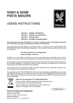
WM400-L / WM400D-L
WM400-R / WM400D-R
Wireless Receivers
English
User’s Manual
WM 400-R / 400D-R / 400-L / 400D-L
WM400-L/WM400D-L
WM400-R/WM400D-R
Wireless Receivers
CONTENTS
INTRODUCTION........................................................................................................................................4
FEATURES...................................................................................................................................................4
PRODUCT DESCRIPTION......................................................................................................................5
WM-400(D) POWER MODES.................................................................................................................7
THE WM400D’S DIGITAL FEATURES.................................................................................................8
ATTACHING THE UNIT TO A SPEAKER.............................................................................................9
DIMENSIONS............................................................................................................................................10
SPECIFICATIONS....................................................................................................................................11
EQ PRESETS............................................................................................................................................12
Phonic reserves the right to improve or alter any information suppied within this document without prior notice.
V1.1 AUG 08, 2006
WM 400-R / 400D-R / 400-L / 400D-L
INTRODUCTION
FEATURES
Congratulations on your purchase of the
WM400(D) wireless receiver, to be used
in conjunction with the WM60 or WM70
wireless transmitters. With either the stereo
or mono WM kits, you are now fast on your
way to becoming completely wireless in your
audio set up. The WM modules are not only
fantastic in style and convenience, however;
they are incredibly easy to use, as this
manual will no doubt prove.
●
Please have a thorough read of this user’s
manual before operating the WM modules.
Inside this guide you will find information on
the ease of your wireless set up, as well as
some great troubleshooting tips and a complete run-down on your modules’ features.
After reading, place the manual in an easy to
remember place so that you can come back
to it in future if ever necessary.
●
●
●
●
●
●
●
●
●
Working with the WM60 or WM70 transmitter to form a wireless system for saving the audio cables between your mixer
and active speakers
Stand-alone UHF wireless receiver,
compatible with WM60 and WM70 transmitters
12VDC external power supply (country
dependent)
16 user-selectable frequencies
RF carrier frequency range:
614.175 - 804.800 MHz (FCC)
614.175 - 864.800 MHz (CE)
Operating range: 210 ft. (70m, environment dependent)
Indicators for power on, AF and RF
Antenna: external, threaded connector
Audio output connectors: XLR out
M6, M8, M10 screws and Velcro strip
included for attaching WM400(D) to any
speakers
WM400D-L or WM400D-R plus:
300 ms digital delay processor for com-
●
pensation of different distance speakers
0.1 millisecond to 300.0 millisecond de-
lay range, delay adjustment may be
made with 0.1 millisecond precision
30 preset EQ curves and variable high
cut and low cut filters
4-digit display to indicate frequency
channel and delay, plus AF, RF and delay bypass indicators
●
●
●
WM 400-R / 400D-R / 400-L / 400D-L
PRODUCT DESCRIPTION
These wireless receivers can be used in conjunction with any active speaker. The receiver
can be attached to the speaker by screwing it
into the stand’s screw socket.
1.
2.
3.
4 Digit Display
(WM400D-L and WM400D-R only)
This display will allow users to see the
properties that are currently in use by
the WM400D, whether you are adjusting
the receiver channel (indicated by CH),
the EQ settings (indicated by EQ), the
delay time (indicated by only the delay
time in milliseconds) or the high and
low pass filters (indicated by a H or L,
respectively). When this unit is powered,
the 4 digit display will light up.
1
10
5
4.
Bypass Indicator
(WM400D-L and WM400D-R only)
This LED will light up when the digital
processing feature of the WM400(D) receiver is off.
5.
Power Button
hold this button down for 2 seconds to
power up the unit.
6.
Bypass Button
(WM400D-L and WM400D-R only)
Push this button to turn the digital
processing feature on and off.
WM 400-R / 400D-R / 400-L / 400D-L
8
WM400
AF Indicators
When this LED is illuminated, it indicates
that there is an audio signal being
received by the WM400(D) receiver.
RF Indicators
When the RF indicator illuminates, it
shows that the transmitter’s signal is
being received successfully. If for some
reason this LED does not turn on, check
your DC power input and pre-set channel configuration and try again.
9
1
10
1
4
5
6
7
WM400D
7.
8.
Up and Down Buttons
(WM400D-L and WM400D-R only)
These buttons are used to adjust the
properties of various features built-into
the WM400D’s. Pushing up or down will
initially simply allow users to adjust the
channel that the transmitter is using. If
you push both of these buttons at the
same time, it will jump to the next setting
that can be edited. You can then adjust
the properties by pushing the up and
down buttons. These settings will come
in the following order:
Channel Settings: CH 0 – CH 9,
CH A – CH F
Delay Settings: 0.0 – 300.0 milliseconds
EQ Mode: P1 – P30 (see the EQ table
for a full rundown on EQ presets)
Low Cut Filter: L 20 (Hz) – L 12 (kHz)
High Cut Filter: H 20 (kHz) – H 60 (Hz)
11. DC In and clip
Plug DC end of the supplied DC power
adaptor (12V, 200mA) into this jack, and
the other end into a suitable AC power
source to allow the WM400(D) to be
powered. The accompanying clip ensures the DC head of the power supply
is kept securely in place.
12. XLR Output
This jack accepts XLR connectors to
feed the signal from the Wireless Receiver to the Speaker.
13. Fixing
Use this hole to secure the WM400(D)
receiver into the mounting socket of your
speaker by use of the accompanying
M6, M8 or M10 screws and a washer.
The high and low cut filters are adjusted in 1 Hz
increments; 10 Hz increments when over 1 kHz.
Channel Selector
(WM400-L and WM400-R only)
Adjusting this dial to one of the preset
channels allows the WM400 to know
which pre-set frequency to look for
the wireless information. The wireless
transmitter should be set to the identical
channel if transmission is to occur successfully.
10
1
10
11
5
9
8
WM400
9. On Indicator
1
(WM400-L and WM400-R only)
This LED indicator illuminates when the
WM400(D) receiver is powered.
1
10. Antenna
This is the WM400(D)’s antenna. Adjust
it so it sits in a vertical position when the
device is in use (change the position if
the wireless signal quality is poor). Push
the antenna in to release it before adjusting its position.
10
1
4
5
6
7
WM400D
WM 400-R / 400D-R / 400-L / 400D-L
WM400(D) POWER MODES
Since some users will mount their WM400(D)
with a speaker in a high position, Phonic
thought it would be handy to make it so users could keep the power on constantly, as
long as power is supplied to the unit and thus
avoiding having to climb up high to push the
power button. To make this adjustment, users
are advised to follow the follow procedure:
1. Remove the two screws on the rear of the
WM400(D) receiver and the antenna.
2. Remove the screw on the bottom of the
WM400(D) beside the XLR output (the
screw closer to the rear panel)
3. Remove the rear section of the casing by
gripping the WM400(D) on both sides,
squeezing and lifting up, in the process
detaching the small clips within the casing.
4. A small switch should be visible on the
PCB. Flick it to the left to ensure the power
of the WM400(D) does not turn off without
you pushing the power button.
5. Be sure to replace the casing and screws
before using the WM400(D) receiver.
Unscrew the antenna
Unscrew the two screws
located on the rear panel
Unscrew the screw on
just below the XLR jack
Move the switch to the left to ensure the
power i s always on. T o the right, the
power button will need to be pushed and
held down to turn the unit on.
WM 400-R / 400D-R / 400-L / 400D-L
THE WM400D’S DIGITAL FEATURES
Channel Mode
The channel number of the WM400D will be
displayed in the 4 digit display, unless adjustments are being made to other feature’s
properties. The channel number set should
match that of the WM60 or WM70 transmitter to allow the wireless system to work successfully.
Delay Mode
High Cut Filter
The high cut filter allows users to remove
unwanted high-frequency sounds, which can
help to remove high frequency hiss and feedback, as well as make the audio signal more
suitable for use with subwoofer speakers.
The high cut filter’s cut off frequency is adjusted in 1 Hz increments (10 Hz increments
over 1kHz) between 20 kHz and 60 Hz. The
default setting is 20 kHz.
Changing the delay allows audio engineers to
compensate for the distance between speakers on stage and audience members at the
rear of the venue. Using the delay effect on a
speaker at the rear will ensure the audio from
the stage reaches audience members at the
rear at approximately the same time as the
audio from the rear-speaker. The delay time
is adjusted in 0.1 millisecond increments, between 0 and 300 milliseconds (holding the up
or down button down speeds up the adjustment time)
EQ Mode
The different EQ modes allow users to adjust
various frequencies of audio to enhance certain instruments, remove sibilance, feedback
and other undesirable noises, and improve
the overall fidelity of sounds. There are 30
presets to choose from (check EQ Preset
page for more information), the titles of which
describe what the effect does to your audio.
The default setting, P0, is completely flat.
Low Cut Filter
A low cut filter allows users to cut low frequency sounds, ensuring stage rumble and
other unwanted low-frequency sounds are
removed from your audio. This can also help
adjust the frequency to be more suitable for
use with tweeters. The low cut filter’s cut off
frequency is adjusted in 1 Hz increments (10
Hz increments over 1kHz) between 10 Hz
and 12 kHz. The default setting is 40 Hz.
WM 400-R / 400D-R / 400-L / 400D-L
ATTACHING THE UNIT TO A SPEAKER
Users can connect the WM400(D) Receiver modules to an active speaker using a mounting
point or the included velcro strips, as indicated.
Mounting Point
WM 400-R / 400D-R / 400-L / 400D-L
Velcro Strip
DIMENSIONS
79.5 / .1
18.5 / 5.1
5 / 1.4
* All measurements are shown in mm/inches.
10
WM 400-R / 400D-R / 400-L / 400D-L
SPECIFICATIONS
WM400-L / WM400-R
RF Sensitivity
-100 dBm
Image Rejection
75dB
T.H.D.
<0.5% @ 1KHz
LED indicator
Power On, RF, AF
Squelch
Pilot Tone & Noise Mute
Audio Output Connector
XLR
Output Impedance
200Ω
Power Requirement
12VDC external power supply (country dependent)
Overall Dimensions (WxHxD)
88.5 x 133 x 36.7 mm (3.5” x 5.2” x 1.4”)
Net Weight
145 g (0.32 lbs)
WM400D-L / WM400D-R plus:
Digital Delay
0.1 millisecond to 300.0 millisecond delay range,
delay adjustment may be made with 0.1 millisecond
precision
Extra features
30 preset EQ, Low-cut and High-cut filter
Diplay
4-digit display for delay time, frequency channel, EQ
mode and Hi-cut/Lo-cut modes
Controls
power on/off, Digital processing bypass, up and down
WM 400-R / 400D-R / 400-L / 400D-L
11
12
Darken
Speech
Smooth
EQ PRESETS
WM 400-R / 400D-R / 400-L / 400D-L
Smile
Brighten
Warmth
WM 400-R / 400D-R / 400-L / 400D-L
13
Snare Drum
Acoustic Guitar
Vocal
14
WM 400-R / 400D-R / 400-L / 400D-L
Telephone
Loud
Techno
WM 400-R / 400D-R / 400-L / 400D-L
15
16
WM 400-R / 400D-R / 400-L / 400D-L
Narrow Boost (800Hz)
Narrow Cut (80Hz)
Hum Reduction
WM 400-R / 400D-R / 400-L / 400D-L
17
Narrow Cut (2.5 kHz)
Narrow Cut (8 kHz)
Vinyl Warmth
Mini-TV
Air Boost
Acoustic Guitar Air
18
WM 400-R / 400D-R / 400-L / 400D-L
WM 400-R / 400D-R / 400-L / 400D-L
19
Cardboard Tube
Bathtub
Tape Hiss Reduction
20
WM 400-R / 400D-R / 400-L / 400D-L
Electric Guitar Bandlimit
Rap Drums Hype
Sizzle Cymbals
Distant
Next-Door Nighbor
Nasal
WM 400-R / 400D-R / 400-L / 400D-L
21
TO PURCHASE ADDITIONAL PHONIC GEAR AND ACCESSORIES
To purchase Phonic gear and optional accessories, contact any authorized Phonic distributor. For
a list of Phonic distributors please visit our website at www.phonic.com and click on Get Gear. You
may also contact Phonic directly and we will assist you in locating a distributor near you.
SERVICE AND REPAIR
Phonic has over 100 service centers worldwide. For replacement parts, service and repairs please
contact the Phonic distributor in your country. Phonic does not release service manuals to
consumers, and advice users to not attempt any self repairs, as doing so voids all warranties. You
can locate a dealer near you at www.phonic.com.
WARRANTY INFORMATION
Phonic stands behind every product we make with a no-hassles warranty. Warranty coverage
may be extended, depending on your region. Phonic Corporation warrants this product for a
minimum of one year from the original date of purchase against defects in material and workmanship under use as instructed by the user’s manual. Phonic, at its option, shall repair or replace the
defective unit covered by this warranty. Please retain the dated sales receipt as evidence of the
date of purchase. You will need it for any warranty service. No returns or repairs will be accepted
without a proper RMA number (return merchandise authorization). In order to keep this warranty
in effect, the product must have been handled and used as prescribed in the instructions
accompanying this warranty. Any tempering of the product or attempts of self repair voids all
warranty. This warranty does not cover any damage due to accident, misuse, abuse, or
negligence. This warranty is valid only if the product was purchased new from an authorized
Phonic dealer/distributor. For complete warranty policy information, please visit
http://www.phonic.com.
CUSTOMER SERVICE AND TECHNICAL SUPPORT
We encourage you to visit our online help at http://www.phonic.com/help/. There you can find
answers to frequently asked questions, tech tips, driver downloads, returns instruction and other helpful
information. We make every effort to answer your questions within one business day.
Phonic America Corporation
6103 Johns Road, #7
Tampa, FL 33634
(813) 890-8872
[email protected]
http://www.phonic.com


![User`s Manual WM400 自動水質監視装置 [スタイル:S4]](http://vs1.manualzilla.com/store/data/006602587_3-3bb684fcf5ad3f67c7b561aa5125f3ed-150x150.png)