1
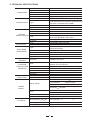
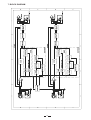
User's Manual
FLEX plus
SOUND ENHANCEMENT
PROCESSOR
R
LTO
www.altoproaudio.com
Version 1.0 November 2003
English
the recommended fuse type as indicated in this
manual. Do not short-circuit the fuse holder. Before
replacing the fuse, make sure that the product is
OFF and disconnected from the AC outlet.
SAFETY RELATED SYMBOLS
CAUTION
RISK OF ELECTRIC SHOCK
DO NOT OPEN
Protective Ground
This symbol, wherever used, alerts you to the presence of un-insulated and dangerous voltages within the product enclosure. These are voltages that
may be sufficient to constitute the risk of electric
shock or death.
Before turning the product ON, make sure that it is
connected to Ground. This is to prevent the risk of
electric shock.
Never cut internal or external Ground wires. Likewise,
never remove Ground wiring from the Protective
Ground Terminal.
This symbol, wherever used, alerts you to important operating and maintenance instructions.
Please read.
Operating Conditions
Always install in accordance with the manufacturer's
instructions.
Protective Ground Terminal
Denotes the product is turned on.
To avoid the risk of electric shock and damage, do
not subject this product to any liquid/rain or moisture.
Do not use this product when in close proximity to
water.
OFF: Denotes the product is turned off.
Do not install this product near any direct heat source.
WARNING
Do not block areas of ventilation. Failure to do so
could result in fire.
AC mains (Alternating Current)
Hazardous Live Terminal
ON:
Describes precautions that should be observed to
prevent the possibility of death or injury to the user.
Keep product away from naked flames.
IMPORTANT SAFETY INSTRUCTIONS
CAUTION
Read these instructions
Describes precautions that should be observed to
prevent damage to the product.
Follow all instructions
Keep these instructions. Do not discard.
WARNING
Heed all warnings.
Power Supply
Only use attachments/accessories specified by the
manufacturer.
Ensure that the mains source voltage (AC outlet)
matches the voltage rating of the product. Failure
to do so could result in damage to the product and
possibly the user.
Power Cord and Plug
Do not tamper with the power cord or plug. These are
designed for your safety.
Unplug the product before electrical storms occur
and when unused for long periods of time to reduce
the risk of electric shock or fire.
Do not remove Ground connections!
If the plug does not fit your AC outlet seek advice from
a qualified electrician.
External Connection
Always use proper ready-made insulated mains
cabling (power cord). Failure to do so could result
in shock/death or fire. If in doubt, seek advice from
a registered electrician.
Protect the power cord and plug from any physical
stress to avoid risk of electric shock.
Do Not Remove Any Covers
Cleaning
Within the product are areas where high voltages
may present. To reduce the risk of electric shock do
not remove any covers unless the AC mains power
cord is removed.
When required, either blow off dust from the product
or use a dry cloth.
Do not place heavy objects on the power cord. This
could cause electric shock or fire.
Do not use any solvents such as Benzol or Alcohol.
For safety, keep product clean and free from dust.
Covers should be removed by qualified service
personnel only.
Servicing
Refer all servicing to qualified service personnel only.
No user serviceable parts inside.
Do not perform any servicing other than those instructions contained within the User's Manual.
Fuse
To prevent fire and damage to the product, use only
1
PREFACE
Dear Customer:
Thanks for choosing FLEX plus Sound Enhancement Processor and thanks for choosing one of the results of
AUDIO TEAM job and researches.
LTO
For our LTO AUDIO TEAM, music and sound are more than a job...are first of all passion and let us say...our
obsession!
We have been designing professional audio products for a long time in cooperation with some of the major brands in
the world in the audio field.
The LTO line presents unparalleled analogue and digital products made by Musicians for Musicians in our R&D
Centres in Italy, Netherlands, United Kingdom and Taiwan. The core of our digital audio products is a sophisticated
DSP (Digital Sound Processor) and a large range of state of the art algorithms which have been developed by our
Software Team for the last 7 years.
Because we are convinced you are the most important member of LTO AUDIO TEAM and the one confirming the
quality of our job, we like to share with you our work and our dreams, paying attention to your suggestions and your
comments.
Following this idea we create our products and we will create the new ones! From our side, we guarantee you and we
will guarantee you also in future the best quality, the best fruits of our continuous researches and the best prices.
Our FLEX PLUS is the result of many hours of listening and tests involving common people, area experts, musicians
and technicians.
The result of this effort is that you can acquire an extremely efficient and universal dynamics processor. It contains
several circuit designs which make the unit an ultimate dynamic processor: multi-band processor, bass processor and
surround processor, which can produce a more lively, transparent and natural sound signal.
Nothing else to add, but that we would like to thank all the people that made the FLEX plus a reality available to
our customers, and thank our designers and all the LTO staff, people who make possible the realization of products
containing our idea of music and sound and are ready to support you, our customers, in the best way, conscious that
you are our best richness.
Thank you very much.
LTO AUDIO TEAM
2
TABLE OF CONTENTS
1. INTRODUCTION........................................................................................................................................4
2. FEATURE LIST.........................................................................................................................................4
3. CONTROL ELEMENTS............................................................................................................................4
3.1 The Front Panel
3.1.1 MULTIBAND PROCESSOR Section
3.1.2 BASS PROCESSOR Section
3.1.3 SURROUND PROCESSOR Section
3.2 The Rear Panel
4. INSTALLATION AND CONNECTION.......................................................................................................7
4.1 Mains Connection
4.2 Audio Connection
4.3 Rack Mounting
5. APPLICATION.......................................................................................................................................9
6. TECHNICAL SPECIFICATION..............................................................................................................11
7. BLOCK DIAGRAM ................................................................................................................................12
8. WARRANTY...........................................................................................................................................13
3
1. INTRODUCTION
LTO products by purchasing our FLEX plus Sound Enhan-
Thank you very much for expressing your confidence in
cement Processor.
With the FLEX plus you have acquired a powerful Sound Enhancement Processor which is based on many years of
experience and findings in processor technology and is used through the world in renowned studios. The FLEX plus
meets highest and non-compromise requirements in terms of operation, sound, specifications and workmanship.
The FLEX plus is able to provide better stereo effect and increase the transparency and presence of sound. It can
precisely modify the bass "contour" for more lively and natural sound. For more detailed information, please read this
manual carefully.
2. FEATURE LIST
Mountable in one standard unit 19"
Illuminated power switch
Automatically reducing unwanted noise in the system
Multi-band processor for bass and high frequency transparency
Bass processor compensates power loss in the bass with its selectable-frequency phase shift and sub-bass enhancement
Surround processor improves the intensity of the stereo effect and provides a more ambient and spatial music field
Balanced XLR and 1/4" TRS connectors available for inputs and outputs
High quality components and rigid configuration for long life and full credibility
Manufactured under QS9000, VDA6.1 certified management system
3. CONTROL ELEMENTS
3.1 The Front Panel
3
EFFECT
R
LTO
INPUT LEVEL (dB)
CHANNEL 1
3
4
4.5
2.2
12
0
2
INPUT LEVEL (dB)
12 CLIP
12
3
3
3.3
2
2
4
ULTRA-LOW
AUTO REDUCTION
5 1.5
1
5
5
1
0
6
12
SENSITIVITY
6
1
(KHz)
TUNE
EXCITER
ENHANCER
PROCESS
0
6
0
SOLO
ON
SOFT
OFF
5
1
LOW MIX
NORMAL
6
SURROUND
FLEX plus
3
4.5
2.2
5 1.5
1
4
2
5
5
1
ON
SOFT
0
6
SHIFT
SURROUND PROCESSOR
4
AUTO REDUCTION
5
1
3.3
2
4
LOW
0
CHANNEL 2
3
3
MODE
BASS PROCESSOR
EFFECT
12 CLIP
2
4
ULTRA-LOW
6
SHIFT
HIGH MIX
MULTIBAND PROCESSOR
NORMAL
5
1
LOW
Bypass
0
3
2
4
0
MODE
6
Bypass
LOW MIX
SENSITIVITY
BASS PROCESSOR
6
1
(KHz)
TUNE
EXCITER
ENHANCER
PROCESS
MULTIBAND PROCESSOR
2
0
6
SOUND
ENHANCEMENT
PROCESSOR
OFF
SOLO
HIGH MIX
POWER
1
Your LTO FLEX plus presents with surround processor and two identical channels, and each channel is
equipped with the multi-band processor and bass processor, which contains 5 push-button switches, 5 rotary
controls and 17 LEDs.
1. POWER Switch
Turn the apparatus ON or OFF.
2. BYPASS Switch
Engaging this switch will bypass the corresponding channel, the input signal will be routed to output directly.
It is used to compare quickly the processed and unprocessed signal.
3. INPUT LEVEL Meter
The meter informs you the input level, with a range of -12dB to +12dB. The CLIP LED will light up when
the distortion occurs in the circuit.
4
3.1.1 MULTIBAND PROCESSOR Section
7
5
EFFECT
CHANNEL 1
3
4
2
R
LTO
3
3.3
4.5
2.2
4
2
AUTO REDUCTION
5 1.5
1
0
Bypass
5
6
6
1
12
(KHz)
TUNE
SENSITIVITY
5
1
EXCITER
ENHANCER
PROCESS
0
6
SOLO
HIGH MIX
MULTIBAND PROCESSOR
8
6
9
10
4
4. SOLO Switch
Engaging this switch is used to select the solo mode, and the switch is turned into red. It is used to
mute the original signal from main mix signal.
5. AUTO REDUCTION Switch
Engage this switch to activate the auto reduction function, which is used to reduce the undesired noise
in the system. If releasing the switch, the auto reduction function will have no any effect on the unit, then
the FLEX plus works under the maximum effect, and all EFFECT LEDs will light up.
6. SENSITIVITY Control
In order to achieve the proper effect, you can rotate this control to adjust the sensitivity for input signal
depending on the EFFECT LED display.
7. EFFECT LED Display
These LEDs will inform you the actually effect change and the amount of sound enhancement. The
first LED is always illuminated even at low-level signals.
8. TUNE Control
Through adjusting this control to select the proper cutoff frequency for high pass filter (or low-cut filter,
which is used to reduce or eliminate the frequencies below the cutoff frequency) within a range of 1kHz
to 6kHz.
9. PROCESS Control
Through rotating this control to achieve an increase in apparent loudness in the high frequencies well.
There are two settings: clockwise for enhancer setting; counterclockwise for exciter setting. The only
difference is intensity of increasing between the two settings.
10. HIGH MIX Control
This control is used to adjust the amount of high frequency signal for sound enhancement. It covers a
range from 0 to 6.
3.1.2 BASS PROCESSOR Section
INPUT LEVEL (dB)
12
0
12 CLIP
3
4
2
ULTRA-LOW
NORMAL
5
1
SOFT
LOW
0
6
MODE
SHIFT
LOW MIX
BASS PROCESSOR
11
12
5
13
11. SHIFT Switch
Through this switch to select the cutoff frequency for low pass filter (or high cut filter) between the
LOW and ULTRA-LOW.
12. LOW MIX Control
This control is used to adjust the amount of low frequency signal for sound enhancement. It covers a
range of 0 to 6.
13. MODE Switch
This switch provides two effect modes for bass processor: up for SOFT mode; down for NORMAL mode.
In the SOFT mode, the bass will go through gentle processing, you will hear the bass with very warm and
natural; otherwise, the bass will sound dry and coarse.
3.1.3 SURROUND PROCESSOR Section
3
4
2
ON
5
1
OFF
0
6
SURROUND
SURROUND PROCESSOR
14 15
14. SURROUND Switch
Engaging this switch will activate the surround processor function, which is used to make the cross
talk between the CHANNEL 1 and CHANNEL 2, hence, the function can be used only in linking with
stereo program material. If you don't want to add this effect to signal path, please let the switch free.
15. SURROUND Control
Rotate this control to adjust the intensity of cross talk effect between the two channels within a range
of 0 to 6. Clockwise for increasing the stereo effect, otherwise, for reducing the stereo effect.
3.2 The Rear Panel
16
AC INPUT
TIP/PIN 2
RING/PIN 3
SLEEVE/PIN 1
110-120V
95-120V /210-240V 60-50Hz
Rated Power Consumption 16W
220-240V
210-240V: T315mAL 250VAC
95-120V: T500mAL 250VAC
REPLACE FUSE WITH CORRECT
TYPE ONLY
Apparaten skall anslutas till
jordat uttag nar den ansluts
till ett natverk
A101
TIP/PIN 2
RING/PIN 3
SLEEVE/PIN 1
2
FUSE:
3
1
3
INPUT
OUTPUT
TIP/PIN 2
RING/PIN 3
SLEEVE/PIN 1
2
CHANNEL 2
17
TIP/PIN 2
RING/PIN 3
SLEEVE/PIN 1
1
INPUT
OUTPUT
CHANNEL 1
19
18
16.FUSE Holder/Voltage Selector
This is a dual voltage unit. Before you attempt to connect and operate the unit, please make sure that your
local voltage matches the voltage on the fuse-holder cover.
Caution: The fuse protecting the AC supplies circuits of this unit. The fuse can only be changed by a
qualified technician, in the event of a fault or changing the supply voltage. If the fuse continues to blow
after replacing, discontinue use of this unit before repaired.
6
220-240V
110-120V
220-240V
110-120V
THIS IS SET FOR
220V AC TO 240V
AC OPERATION
THIS IS SET FOR
110V AC TO 120V
AC OPERATION
The fuse-holder above the AC connector on the rear of the chassis has 3 triangular markers(please refer
to the above pictures), with two of these triangles opposing each other, your unit is set to the operating
voltage printed next to these markers.
To change, pull fuse-holder out and rotate 180 , then push in again.
17.AC Inlet
This connector is used to connect the supplied power cord. Please don't plug power cord into this unit
and AC power if voltage has not been correctly set.
18. Audio In
These connectors are used to input the signal source. You can input the signal via the balanced 1/4" TRS
phone jack or XLR connector.
19. Audio Out
These connectors are used to output the signal source. You can output the signal via the balanced 1/4"
TRS phone jack or XLR connector.
4. INSTALLATION AND CONNECTION
4.1 Mains Connection
FLEX plus is provided with dual voltage plug. You must check the power supply voltage available in your country
before connecting the power cord in the wall outlet.
4.2 Audio Connection
The FLEX plus Sound Enhancement Processor is equipped with balanced XLR connectors as well as 1/4" phone
jack and can be connected with other units in different ways to support a vast range of applications without
experiencing a signal loss.
a. Wiring Configuration
Both types of connectors available on FLEX plus can be wired in balanced and unbalanced modes.
Please see following drawing for details.
For 1/4" Phone jack
+
+
-
Tip
Ring
Tip
Sleeve
Sleeve
TS Type Unbalanced
TRS Type Balanced
7
+
Ring
Tip
Sleeve
TRS Type Unbalanced
For XLR connector
Pin2 (+)
Pin3 (-)
(Linked to Pin1 manually,
Pin2 (+)
Pin3 (-)
)
Pin1 ( )
Pin1 ( )
XLR Type Unbalanced
XLR Type Balanced
b. In Line Connection
Please see following drawing for details.
Balanced
SLEEVE RING TIP
TIP RING SLEEVE
Tip
Ring
Sleeve
3
3
1
1
2
2
1
3
2
TIP RING SLEEVE
Tip
Ring
Sleeve
1
2
1
2
3
3
Tip
Ring
1
2
3
Sleeve
Unbalanced
1
Tip
Ring
3
2
Sleeve
TIP RING SLEEVE
Tip
1
3
2
Sleeve
1
2
3
1
2
3
1
TIP SLEEVE
2
3
1
2
3
Tip
TIP SLEEVE
SLEEVE TIP
Sleeve
Tip
Ring
TIP RING SLEEVE
SLEEVE RING TIP
Cent r e
Screen
Tip
Sleeve
Tip
Ring
Sleeve
Sleeve
Tip
Cent r e
Sleeve
Screen
Tip
Ring
Centre
Sleeve
Screen
TIP SLEEVE
TIP RING SLEEVE
3
3
1
1
2
2
1
2
3
1
2
3
c. Insert Points Connection
In case you are using the main inserts of your mixing console and you have a single jack for SEND and RETURN,
you can use an insert Y cable. Please see following drawing.
1/4" TRS insert
Send
Return
Gnd/Screen
Ring
Tip
Sleeve
8
-. As In-Line Processor
AC INPUT
TIP/PIN 2
RING/PIN 3
SLEEVE/PIN 1
110-120V
95-120V /210-240V 60-50Hz
Rated Power Consumption 16W
TIP/PIN 2
RING/PIN 3
SLEEVE/PIN 1
220-240V
2
FUSE:
210-240V: T315mAL 250VAC
95-120V: T500mAL 250VAC
REPLACE FUSE WITH CORRECT
TYPE ONLY
Apparaten skall anslutas till
jordat uttag nar den ansluts
till ett natverk
A101
TIP/PIN 2
RING/PIN 3
SLEEVE/PIN 1
TIP/PIN 2
RING/PIN 3
SLEEVE/PIN 1
2
1
1
3
3
INPUT
OUTPUT
INPUT
OUTPUT
CHANNEL 2
CHANNEL 1
Channel insert
-. As Effects Device
AC INPUT
TIP/PIN 2
RING/PIN 3
SLEEVE/PIN 1
110-120V
95-120V /210-240V 60-50Hz
Rated Power Consumption 16W
TIP/PIN 2
RING/PIN 3
SLEEVE/PIN 1
220-240V
2
FUSE:
210-240V: T315mAL 250VAC
95-120V: T500mAL 250VAC
REPLACE FUSE WITH CORRECT
TYPE ONLY
A101
Apparaten skall anslutas till
jordat uttag nar den ansluts
till ett natverk
TIP/PIN 2
RING/PIN 3
SLEEVE/PIN 1
CHANNEL 1
AUX Return
AUX Send
10
INPUT
OUTPUT
CHANNEL 2
AUX Return
1
3
INPUT
OUTPUT
TIP/PIN 2
RING/PIN 3
SLEEVE/PIN 1
2
1
3
AUX Send
6. TECHNICAL SPECIFICATIONS
AUDIO INPUT
Connectors
Type
XLR and 1/4" TRS
RF filtered, servo-balanced input
Max. Input Level
Balanced and Unbalanced: +21 dBu (unity gain)
Balanced: 50kOhm Unbalanced: 25kOhm
typ.40dB, >55dB@1kHz
XLR and 1/4" TRS
Electronically servo-balanced output stage
(optional transformer-balanced). Automatic level
correction for unbalanced use (6dB).
Balanced and Unbalanced: +21 dBu, +20 dBm
Balanced: 60 Ohm Unbalanced: 30 Ohm
20Hz to 20kHz, +0/-0.5dB
0.35Hz to 200kHz, +0/-3dB
>95dBu, unweighted, 22Hz to 22kHz
0.008% typ. @+4dBu, 1kHz, Gain 1
0.04% typ. @+20dBu, 1kHz, Gain 1
0.01% typ. SMPTE
<-100dB, 22Hz to 22 kHz
"Dual Mode" bass processor
Variable: from 0 to 6
"Natural Sonic" processor with VSP (Variable
Sound Processing)
Impedance
CMRR
Connectors
AUDIO OUTPUT
SYSTEM
SPECIFICATIONS
BASS
PROCESSOR
Type
Max. Output Level
Impedance
Bandwidth
Frequency Response
Noise
THD
IMD
Crosstalk
Type
Low Mix
Type
MULTI-BAND
PROCESSOR
SURROUND
SECTION
FUNCTION
SWITCHES AND
CONTROLS
INDICATORS
NR Sensitivity
Tune
Process
High Mix
Variable: from 0 to 6
Variable: from 1 to 8 kHz
Variable: from Enhancer to Exciter
Variable: from 0 to 6
Surround
Variable: from 0 to 6
Shift
Switches the frequency of the bass processor
between "low" and "ultra-low"
Mode
Auto NR
In/Out
Solo
Surround
Effect
Function switch
Switches the bass sound from "soft" to "tight"
Activates the noise reduction system
Activates the relay controlled hard-bypass
Monitors the pure effect signal (solo function)
Activates the surround processor
13 LED meter indicates the effect
LED indicator for each function switch
USA/Canada
120V , 60Hz
U.K./Australia
240V , 50Hz
Europe
230V , 50Hz
General export model 100-120V ,
200-240V , 50-60Hz
Mains voltage
POWER
SUPPLY
95-120V : T 500mAL
210-240V : T 315mAL
Max. 16 Watts
Standard IEC receptacle
1 3/4" (44.5mm) 19" (482.6mm)
1/2" (217mm)
Fuse
Power consumption
Mains connection
PHYSICAL
Dimensions (H
W
D)
Net Weight
Shipping Weight
Approx.2.2kg
Approx.3.4kg
11
8
7. BLOCK DIAGRAM
12
8. WARRANTY
1. WARRANTY REGISTRATION CARD
To obtain Warranty Service, the buyer should first fill out and return the enclosed Warranty Registration Card within
10 days of the Purchase Date.
All the information presented in this Warranty Registration Card gives the manufacturer a better understanding of
the sales status, so as to purport a more effective and efficient after-sales warranty service.
Please fill out all the information carefully and genuinely, miswriting or absence of this card will void your warranty
service.
2. RETURN NOTICE
2.1 In case of return for any warranty service, please make sure that the product is well packed in its original shipping
carton, and it can protect your unit from any other extra damage.
2.2 Please provide a copy of your sales receipt or other proof of purchase with the returned machine, and give detail
information about your return address and contact telephone number.
2.3 A brief description of the defect will be appreciated.
2.4 Please prepay all the costs involved in the return shipping, handling and insurance.
3. TERMS AND CONDITIONS
3.1
LTO warrants that this product will be free from any defects in materials and/or workmanship for a period
of 1 year from the purchase date if you have completed the Warranty Registration Card in time.
3.2 The warranty service is only available to the original consumer, who purchased this product directly from the
retail dealer, and it can not be transferred.
3.3 During the warranty service, LTO may repair or replace this product at its own option at no charge to you for
parts or for labor in accordance with the right side of this limited warranty.
3.4 This warranty does not apply to the damages to this product that occurred as the following conditions:
Instead of operating in accordance with the user's manual thoroughly, any abuse or misuse of this product.
Normal tear and wear.
The product has been altered or modified in any way.
Damage which may have been caused either directly or indirectly by another product / force / etc.
Abnormal service or repairing by anyone other than the qualified personnel or technician.
And in such cases, all the expenses will be charged to the buyer.
3.5 In no event shall LTO be liable for any incidental or consequential damages. Some states do not allow the exclusion
or limitation of incidental or consequential damages, so the above exclusion or limitation may not apply to you.
3.6 This warranty gives you the specific rights, and these rights are compatible with the state laws, you may also
have other statutory rights that may vary from state to state.
13
SEIKAKU TECHNICAL GROUP LIMITED
No. 1, Lane 17, Sec. 2, Han Shi W. Road, Taichung, 401 Taiwan
http://www.altomobile.com Tel: 886-4-22313737
email: [email protected] Fax: 886-4-22346757
All rights reserved to ALTO Mobile. Due to continued development in response to
customer feedback, product features, specifications and/or internal/external design may be
changed without prior notice. No photocopying, translation or reproduction of any part of this user
manual is allowed without prior written permission.Copyright c 2004 Seikaku Technical Group Limited.
NF01500-1.0