1
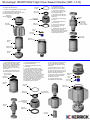
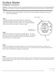
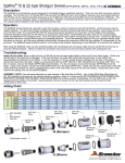
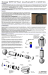
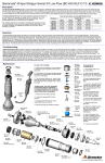
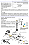
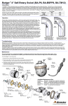
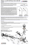
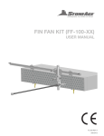
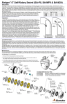
®
®
StoneAge WARTHOG High Flow Sewer Nozzle (WD 1-1/4)
Description:
The WD Warthog 1-1/4” is a Self-Rotary Sewer Nozzle designed for waterblast cleaning of pipes and sewer lines. Jet thrust powers rotation of the head and pulls the
tool through the line. The WD Warthog has a 1-1/4” NPT inlet thread and a head with 6 back jets at 140 degrees and one forward at 15 degrees for rotation. The inlet
is also available in BSP threads.
The WD Warthog 1-1/4" is capable of working pressures up to 5000 psi (350 bar) and flow rates of 80 to 120 gpm, with rotation speeds from 150 to 350 rpm. The unit
is filled with a thick viscous fluid that controls the rotation speed.
The nozzle orifice sizes should match the operating conditions of pressure and flow desired. Hose length and size must be known to correctly determine the proper
orifice sizes. Contact your distributor or www.sewernozzles.com to help in nozzle selection.
®
The most important item in maintaining the Warthog is keeping the tool full of viscous fluid. The tool also has a high pressure seal and seat that will need
to be replaced if the tool begins to leak water from under the Weep Seal (WD 021). The tool may leak water at low pressure intermittently, but if it leaks at or
near operating pressure, it is time to change the seal.
Operation:
A 15-25 foot long section of leader hose of a different color than the jetter hose is recommended to
indicate how close the tool is to exiting the pipe during cleaning. Flush the jetter hose to remove
debris. Pass hose end through the hose guard or Tiger Tail. If the Warthog is being used in pipe
diameters less than 10 inches it can be attached directly to the hose end; if being used in larger
pipes it needs to have a straight rigid pipe or centralizer placed behind the tool so that the rigid length
is greater than the pipe diameter so the tool cannot turn around in the pipe.
Risk of serious injury or death: Do not attempt to clean the manhole with the Warthog
hanging on the hose . The tool can turn around and hit the operator.
Position the Warthog and tiger tail so it is within the pipe to be cleaned. Recommended cleaning
direction is upstream from the manhole. Slowly bring the pump up to pressure, making certain that
the Warthog begins to pull it's way in the proper direction up the pipe; allow it to advance a few feet
and note the location of the leader hose or other hose marker being used. Once the pump is up to
operating pressure, feed out the reel at a reasonable rate to allow the jets time to clean the pipe. If
roots are present, feeding at a slower rate will improve the cleaning results. Depending on the
amount of debris present in the pipe, it may be necessary to occasionally pull the Warthog back
toward the manhole to prevent large buildups of debris behind the tool.
When finished cleaning, withdraw tool back to initial starting point noted by the location of the leader
or hose marker. Shut down and secure pump before removing Warthog from line. Secure the hose
reel and Warthog to keep it from dragging on the ground. If the Warthog will be removed from the
line and stored for more than several days, blow out water with compressed air to prolong the life of
the internal components.
Troubleshooting:
Head will not rotate: First try rotating head by hand and see if it feels rough or gritty to turn. If it does, the tool must be disassembled and repaired; it likely has bad
bearings, seals and fluid. If the tool feels okay, check to see if any nozzles are plugged; even if a nozzle is only partially blocked it can keep the head from rotating.
Nozzles must be removed from the head to properly clean them; it does not do any good to poke the material plugging the nozzle back into the head, as it will just
replug a nozzle.
Head spins too fast: It is likely that the swivel is low on viscous fluid, or the viscous fluid has water in it. The best thing to do is drain all the fluid, wipe the parts clean
and refill with the proper fluid. Check that the shaft seals are still good and will keep the fluid from leaking out.
Seal Leak: The seal may leak initially at low pressure, but should pop closed as pressure is increased. If operating pressure is reached and the seal is leaking
continuously, the high pressure seal may need to be replaced. Refer to the maintenance below.
Seals wear out quickly: The tool must be disassembled and inspected. The brass seat should be checked for being installed in the right direction, and it should be
replaced any time the high pressure seal is replaced. The bore of the shaft where the high pressure seal is located should be checked for grooving. If it is worn larger
than .633", the shaft will need to be replaced.
Maintenance:
*Blow out all water with compressed air before storing tool!
To service the viscous fluid and high pressure seal:
WD 002 or
WD 002-BSPP20
Inlet Nut
1. Unscrew the Inlet Nut (WD 002 or WD 002-BSPP20) from the Body. Hold the Body
by the flats near the head.
2. Check the fluid condition and level. If the fluid appears to have water contamination
or is very dirty, we recommend further disassembly of the tool to clean out the old fluid.
Otherwise, drain out as much of the old fluid as possible and add new viscous fluid to
cover the top bearing and wave spring.
BJ 211
Seat
3. Remove the Seat (BJ 211) and Seal (BJ 212-O) from the bore of the Shaft.
Detailed
Apply grease to a new High Pressure Seal and install in the bore. Install
a new Seat on top of the Seal, with the flat face of the Seat facing
chamfered face
toward the Seal, as shown.
BJ 211
Seat
4. Apply anti-seize to the threads of the Inlet Nut and thread into
the Body. Make sure that the Seat stays centered in the bore of the
Shaft. Tighten to 50 ft-lb torque.
WD 040
Head
if the high pressure
seal is leaking, you
will see water
spraying from under
the Weep
Seal (WD 021)
View:
Check fluid level
(should cover
bearing and wave
spring)
BJ 212-O
H.P. Seal
flat face
WG 003
Body
BJ 212-O
H.P. Seal
BJ 010-D
Shaft Seal
WG 007
Bearing
WG 007
Bearing
WD 001
Shaft
WG 080
Centralizer
BJ 212-O
H.P. Seal
WG 014
Wave Spring
BJ 211
Seat
WD 021
Weep Seal
BJ 010-D
Shaft Seal
WG 008
O-Ring
WD 002 or
WD 002-BSPP20
Inlet Nut
®
®
StoneAge WARTHOG High Flow Sewer Nozzle (WD 1-1/4)
Disassembly:
WG 008
O-Ring
3. Remove the O-Ring
(WG 008) and Weep Seal
(WD 021) from the Inlet Nut.
BJ 010-D
Shaft Seal
4. Remove the Shaft Seal
(BJ 010-D) from the Inlet Nut
if it appears damaged.
To disassemble the Warthog:
1. Unscrew the Head (WD 040) from the Shaft.
2. Unscrew the Inlet Nut (WD 002 or
WD 002-BSPP20) from the Body (WG 003).
Pull off the Centralizer (WG 080).
5. Remove the Seat (BJ 211)
and Seal (BJ 212-O) from the
Shaft bore.
WD 002 or
WD 002-BSPP20
Inlet Nut
WD 002 or
WD 002-BSPP20
Inlet Nut
WD 001
Shaft
6. Remove the Wave Spring
(WG 014).
7. Push the Shaft (WD 001)
out of the Body.
WG 080
Centralizer
WD 021
Weep Seal
do not ding
or raise any
burrs on this
portion of Shaft
8. Remove the Shaft Seal
(BJ 010-D) from the Body
if it is damaged.
9. Carefully pry the Bearings
(WG 007) off of the Shaft.
Make sure not to raise any burrs
on the large diameter portion of
the Shaft with the groove.
BJ 211
Seat
BJ 212-O
H.P. Seal
BJ 010-D
Shaft Seal
WG 014
Wave Spring
WG 003
Body
always hold
Body by flats
WD 040
Head
Assembly:
1. Install Shaft Seals (BJ 010-D) in
the Body (WG 003) and the Inlet
Nut (WD 002 or WD 002-BSPP20).
Both seals are installed so the lip
with the spring faces up when
installing. Apply grease to the lips
of the seals.
2. Install O-Ring (WG 008) and
Weep Seal (WD 021) on Inlet Nut.
lip of seal with
spring faces up
BJ 010-D
Shaft Seal
WG 003
Body
6. Place the Wave Spring (WG 014)
on top of the Bearing. Add more
viscous fluid until the Wave Spring
is covered.
3. Press the Bearings (WG 007)
onto the Shaft (WD 001).
4. Place the Centralizer (WG 080)
over the Body.
5. If you have a Fill Tube (HC 064),
insert it thru the Shaft Seal in the Body
up to it's shoulder. Pour Viscous Fluid
into the Body about 1" deep. Insert
the Shaft into the Body, allowing the
Shaft to push out the Fill Tube. If you
do not have the Fill Tube, insert the Shaft
into the Body and pour viscous fluid into
the Body; allow the fluid to settle down
thru the top bearing and around the Shaft
and keep adding fluid until it covers
the top bearing. It will take about
10 minutes to get the tool full.
7. Apply grease to the H.P. Seal
(BJ 212-O). Insert in bore of Shaft.
8. Place the Seat (BJ 211) on top of
the Seal, with the chamfered end up.
(See the Maintenance Section)
9. Apply anti-seize to the threads
of the Inlet Nut; thread into Body
and tighten to 50 ft-lb.
10. Apply teflon tape to the
shaft threads and install head.
WG 008
O-Ring
BJ 010-D
Shaft Seal
chamfered
end up
BJ 211
Seat
BJ 212-O
H.P. Seal
WG 014
Wave Spring
lip of seal with
spring faces up
WD 002 or
WD 002-BSPP20
Inlet Nut
WD 001
Shaft
WD 021
Weep Seal
HC 064
Fill Tube