1
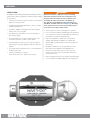
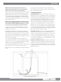
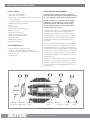
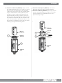
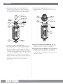
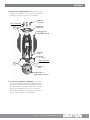
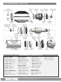
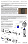
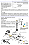
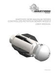
WARTHOG WGR MAGNUM SERIES
CONTROLLED ROTATION SEWER NOZZLE
USER MANUAL
PL-533 (06/2014)
OVERVIEW
WARNING
DESCRIPTION:
The Magnum Series Warthog WGR (hereafter WGR) Controlled
Rotation Sewer Nozzle is designed for waterjet cleaning of pipes
and sewer lines.
• Jet thrust from the water powers the rotation of the head and
pulls the tool through the line.
• The WGR can be provided with either a 1” NPT or 1” BSPP
female threaded inlet nut.
Operations with this equipment can be potentially
hazardous. Caution must be exercised prior to and
during machine and water jet tool use. Please read
and follow all of these instructions, in addition to
the guidelines in the WJTA Recommended Practices
handbook, available online at www.wjta.org. Deviating
from safety instructions and recommended practices
can lead to severe injury and/or death.
• The WGR is capable of working pressures up to 5000 psi
and flow rates of 50 to 80 gpm.
• Always inspect the nozzle for damage prior to operation.
• The carbide face seals allow the use of recycled water or
fresh water for jetting.
• Do not exceed the maximum operating pressure specified for
any component in a system. The immediate work area must
be marked off to keep out untrained persons.
• The nozzle utilizes a rotor and viscous fluid speed control
mechanism to provide consistent rotation speed.
• As with all Warthog nozzles, the orifice sizes are selected
to best match the desired operating conditions of pressure
and flow.
• Hose length and size must be known to correctly determine
the proper orifice sizes.
• Contact your distributor or reference
www.sewernozzles.com to help in nozzle selection.
• Inspect the equipment for visible signs of deterioration,
damage, and improper assembly. Do not operate until
repaired. Make sure all threaded connections are tight and
free of leaks.
• All operators and persons in close proximity must wear
personal protective equipment, including approved
protection for body, hands, feet, face, ears, eyes, and
air passages. Please refer to the WJTA Recommended
Practices, Section 6.
• Inspect the high pressure hose for damage. Only high quality
hoses intended for waterblast applications should be used.
2
866-795-1586 • WWW.SEWERNOZZLES.COM
OPERATION
NOTE: A 15-25 foot long section of leader hose of a
different color than the jetter hose is recommended to
indicate how close the tool is to exiting the pipe.
After the job has been completed, remove the WGR from the
hose and blow out the water with compressed air to prolong the
life of the internal components.
Flush the jetter hose prior to installing the nozzle to remove debris.
Install the hose guard or Tiger Tail. If the WGR is being used in
pipe diameters less than 10 inches it can be attached directly to
the hose end. If being used in larger pipes a straight rigid pipe
or centralizer must be placed behind the tool such that the rigid
length is greater than the pipe diameter to ensure the tool cannot
turn around in the pipe.
TROUBLESHOOTING
Risk of serious injury or death: Do not attempt to clean a
manhole with the WGR hanging by the hose. The tool can
turn around and strike the Operator. Specific accessories
are offered and are required to safely clean manholes.
To clean lines, position the WGR and Tiger Tail so it can enter
the pipe to be cleaned. The recommended cleaning direction is
upstream from the manhole.
Slowly bring the pump up to pressure, making certain that the
WGR begins to pull its way into the pipe in the proper direction;
allow it to advance a few feet and note the location of the leader
hose or other hose marker being used. Once the pump is up to
operating pressure, feed out the reel at a reasonable rate to allow
the jets time to clean the pipe.
If roots are present, feeding at a slower rate will improve the
cleaning results. Depending on the amount of debris in the pipe, it
may be necessary to occasionally pull the WGR back toward the
manhole to prevent buildup of debris behind the tool.
When finished cleaning, withdraw the tool back to its initial starting
point noted by the location of the leader or hose marker.
Head Will Not Rotate: Check to see if any jets, or inserts, are
plugged. Even if a jet is only partially blocked it can keep the head
from rotating. Jets must be removed from the head to be properly
cleaned. Poking the material plugging the jet back into the head
will not fix the problem because it will re-plug the jet once water
starts flowing. If the jets are all clear, wash the nozzle off with
water to remove any debris or grit between the head, body and
shaft. Then try rotating head by hand. It should feel free with a
slight amount of smooth resistance. If it feels rough, gritty, or hard
to turn, the tool needs to be repaired. It may need new bearings
and shaft seals or high pressure seals. It is possible the tool needs
viscous fluid added or changed, but if viscous fluid is confirmed to
be present, a rebuild should be considered.
Head Spins Too Fast: If the nozzle is spinning significantly faster
than normal, or if the nozzle starts to sound different (like a jet
engine or a turbo charger) the nozzle may be low on viscous fluid,
or the viscous fluid may be contaminated. In this case, add or
change the fluid as appropriate. Continued operation in this state
can mechanically damage the tool and a rebuild may be required
to replace the faulty shaft seals.
High Pressure Water Seals Leak: The WGR’s seal design uses
a slight amount of water for lubrication. At full pressure it should
not leak more than a few drops with a new set of seals. The high
pressure seals may need to be replaced if you are not able to get
to full pressure or when a continuous spray comes from under the
WGR 020 Back Plate.
Shut down and secure the pump before removing the WGR from
the line.
Manhole
Tiger Tail
Nozzle
Water Flow Direction
Figure 1. Proper Nozzle Setup
866-795-1586 • WWW.SEWERNOZZLES.COM
3
HEAD REMOVAL/REPLACEMENT
LIST OF TOOLS:
HEAD REMOVAL/REPLACEMENT
• Bench Vice (recommended)
• Arbor Press (recommended)
• Smooth Jaw Adjustable Wrench (such as Crescent® C718
Automotive Wrench)
• Large Adjustable Wrench (such as a 12” Crescent® Wrench)
• Medium size flat-head screw driver
• Pick
• Bearing Splitter
• 3/8 Drive Ratchet with 3” Extension
• WGR 612 Tool Kit
• WGR 180 T-25 L-Wrench
• WGR 181 Removal Press Tube
• WGR 182 Installation Press Tube
• WGR 183 Hex Tool
• WGR 184 HP Seal Press
• WGR 186 HP Seal Puller
LIST OF MATERIALS:
•
•
•
•
•
Clean lint free rags or blue shop towels
Anti-Seize - StoneAge PN (GP 043 Blue Goop)
Lithium Soap Grease – StoneAge PN (GP 048 Grease)
Blue Loctite® 242
Isopropyl Alcohol
***Product training and proper tools are required to
service this nozzle. If you are uncomfortable performing
the service, bring the nozzle to your authorized dealer.*
The use of a bench vice and an arbor press is highly
helpful. Take care throughout the entire procedure
to keep the internals clean and free from grit, lint,
and contamination. Failure to do so could result in
premature failure after service.
The WGR head is easily removed. Different heads can be
configured to match specific jobs. Changing heads is a
quick way to get optimal performance for every job type from flushing lines to removing grease and roots. The shaft
and head utilize an O-Ring and straight thread connection,
eliminating the need for Teflon Tape and decreasing the
change time.
Remove the head. Insert the provided L-Wench (WGR 180)
into the hole through the Front Nut (WGR 004) then rotate
the Head (WGR 040-R31-???) until the L-Wrench slides all
the way through and locks the Shaft (WGR 101) from rotating.
Use one wrench on the Front Nut and another wrench on the
Head to remove the Head. DO NOT loosen the Head using
the Centralizer Fins (WGR 081) or Body (WGR 003) as tool
damage may occur.
Replace the Head. Before reinstalling the head, make sure
the threads on the shaft and in the head are free from grit,
debris, and old Loctite®. Make sure the O-Ring on the shaft
is clean and in good condition. Apply Blue Loctite® 242 to
the Shaft threads.
2a
WGR 030
T-25 Screw
2c
2b
WGR 020
Back Plate
1a
1b
WGR 081
Fin (6)
WGR 003
Body
WGR 180
T-25 Torx Key
Head and Fin Removal
4
866-795-1586 • WWW.SEWERNOZZLES.COM
WGR 101
Shaft
WGR 040
Head
FLUID REPLACEMENT
The Centralizer Fins are replaceable without opening the nozzle.
Specific fin sizes are available to help optimize cleaning in larger
diameter pipes. Keeping the nozzle close to the center of the pipe
will increase the effectiveness of the water jets in cleaning the
entire pipe.
Fin Removal and Replacement. Remove the six Screws (WGR
030) at the rear of the tool using the provided L-Wrench (WGR
180). The Back Plate (WGR 020) and Fins (WGR 081) can now
be removed. Pull the fins rearward and outward. When reinstalling
new fins, make sure the front of the groove is free from debris.
Replace the Back Plate, apply Blue Loctite® 242 to the Screws,
and then tighten the Screws evenly in a star pattern. Tighten
Screws to 20 in-lb.
SPEED CONTROL FLUID CHANGE
The speed control fluid changing is made easy with the WGR and
disassembly of the tool is not required. This means there is less
chance for contamination and longer overall tool life. Fluid changes
should only be performed by qualified persons.
NOTE: Improper fluid change maintenance can result in reduced
bearing or shaft seal life. DO NOT PRESSURIZE THE WGR BODY
by forcing new fluid in too fast. The fluid is thick and only very light
pressure should be applied to the syringe. Excess pressure will
force fluid past the inner shaft seals and into the bearings. Use
extreme care when performing this procedure.
Fluid Replacement
Fill the Syringe (BC 410) with new Viscous Fluid (BJ 048-M).
Position the tool at an angle with one Port Screw (BJ 026) at
the highest point and the other Port Screw at the lowest point
(preferably mounted in a vise). Clean around, then remove the
upper Port Screw from the body. Screw the syringe into the upper
port, then remove the lower Port Screw. Using the assistance
of gravity, gently ease the new fluid into the Body (WGR 003)
while letting the old fluid flow out the opposite hole. Rotate the
Head while flushing. *DO NOT PRESSURIZE THE CHAMBER by
aggressively forcing in fluid.* The fluid is thick and some time is
required to complete the flush. Reinstall the exit Port Screw, then
remove the Syringe and install the inlet Port Screw.
This flushing procedure is only recommended for replacing the
fluid with the same fluid. Not all of the fluid will be replaced using
this procedure, therefore full disassembly and cleaning of the tool
is recommended when changing to a different speed, or viscosity
of fluid.
Tech Tip: The rotation speed of the head can be fine tuned with
three different viscous fluid choices to optimize performance for
specific applications (Slow Fluid: BJ 048-S, Medium Fluid: BJ
048-M and Fast Fluid: BJ 048-F). The medium viscosity fluid is
recommended by StoneAge for maximized performance and
minimized maintenance. Please contact your Dealer or StoneAge
Customer Service to select the right fluid for your application.
The WGR is designed for maximum viscous fluid life and frequent
fluid changes should not be required. A fluid change should be
performed when replacing bearings and shaft seals.
866-795-1586 • WWW.SEWERNOZZLES.COM
5
DISASSEMBLY
DISASSEMBLY
1. Remove the Head (WGR 040-R31-???). Insert the provided
L-Wench (WGR 180 T-25 Torx Key) in through the hole in the
Front Nut (WGR 004) in order to lock the shaft. Rotating the
Head relative to the tool may be required to align the through
hole and the shaft. Completely insert the L-Wrench. Use a
wrench on the Front Nut and a wrench or a vice on the Head
to remove the Head.
5. Remove the Shaft (WGR 101). The Shaft presses out
rearward, toward the Inlet Nut (WGR 102). Fluid may bleed out
of the Port Screw hole during removal. The front Bearing (WGR
007) is pressed into the Body (WGR 003) and should remain in
place. The rear Bearing is pressed onto the shaft and should
slide out with the Shaft, along with the Seal Spacer (WGR 011)
and inner Shaft Seal (WGR 010) when the Shaft is removed.
2. Remove the Fins (WGR 081 or WGR 082). Remove the six
Screws (WGR 030) which attach the Back Plate (WGR 020).
Once the Back Plate is off the Fins can then be removed.
6. Remove the Front Nut (WGR 004) from the Body
(WGR 003). Use care to not ovalize Body. The use of a bench
vice is recommended.
3. Remove the Inlet Nut (WGR 102) from the Body (WGR 003).
Use care to not ovalize Body or Inlet Nut. The use of a bench
vice is recommended.
3
4. Remove forward most Port Screw (BJ 026).
WGR 102
Inlet Nut
WGR 030
T-25 Screw
2
WGR 020
Back Plate
WGR 081 Fin (6)
Or
WGR 082 Ext. Fin (6)
WG 014
Wave Spring
5
WGR 101
Shaft
WGR 003
Body
BJ 026
Port Screw
WGR 003
Body
WGR 180
T-25 Torx Key
1
4
WGR 004
Front Nut
WGR 101
Shaft
6
WGR 040-R31-???
Head (Standard or Puller)
6
866-795-1586 • WWW.SEWERNOZZLES.COM
WGR 004
Front Nut
DISASSEMBLY
7. Press the front Bearing (WGR 007) out of the Body
(WGR 003). Use the Removal Tube (WGR 181) seated against
the inside of the Shaft Seal (WGR 010) to press the Shaft Seal,
Seal Spacer (WGR 011) and Bearing forward out of the Body
(WGR 003), toward the Head.
8. Remove the Shaft Seal (WGR 006) from the Front Nut
(WGR 004). Use care not to scratch or damage the seal bore
of the Front Nut.
9. Remove the Shaft HP Seal (WGR 058-M90). Squeeze the
HP Seal Puller (WGR 186) together and insert it into the bore
of the Shaft HP Seal, then release. The HP Seal Puller should
hook the bottom edge of the Shaft HP Seal; pull upward in
a circular pattern to work the Shaft HP Seal out of the Shaft
(WGR 101). Remove the Wave Spring (WGR 052). *Removing
the Shaft HP Seal is required to prevent it from being damaged
while removing the Bearing (WGR 007) in the next step.*
Inspect the polished faces, if damaged, replace HP Seal set
(WGR 058-M90 and WGR 059-M90) together.
10. Remove O-Rings from the Shaft (WGR 101). Remove
TR200 121 and WS 210. Do not scratch the glands in the
shaft otherwise leakage may occur.
WGR 006
Shaft Seal
8
WGR 181
Removal Tube
WG 008
O-Ring
(6)
WGR 004
Front Nut
12.
INSPECT
9
WGR 003
Body
7
WGR 010
Shaft Seal
WGR 186
HP Seal Puller
WGR 058-M90
Shaft HP Seal
WGR 052
Wave Spring
10
WS 210
O-Ring
WGR 011
Seal Spacer
WGR 007
Bearing
WGR 101
Shaft
10
866-795-1586 • WWW.SEWERNOZZLES.COM
TR200 121
O-Ring
7
DISASSEMBLY
11. Remove the Rear Bearing (WGR 007). Evenly seat a
bearing puller under the Rear Bearing then press on the end
of the Shaft (WGR 101) to remove Bearing. Use care to not
catch or bend the Seal Spacer (WGR 011). The Seal Spacer
and Shaft Seal (WGR 010) will then slip off the shaft.
INSPECT
11
12. Inspect the Shaft (WGR 101). Inspect for grooving where
the four shaft seals ride. Inspect where the bearings ride for
signs of the bearings slipping or scratches which extend into
the area where the seals operate. Inspect the front shaft lock
grooves for interfering deformation. Remove burrs or high
spots by grinding or filing. If any place is severely damaged or
worn, the shaft may need to be replaced.
WGR 059-M90
Nut HP Seal
WGR 052
Wave Spring
WS 210
O-Ring
WGR 102
Inlet Nut
13. Remove the Nut HP Seal (WGR 058-M90). Squeeze the
HP Seal Puller (WGR 186) together and insert it into the bore
of the Nut HP Seal, then release. The HP Seal Puller should
hook the bottom edge of the Nut HP Seal; pull upward in a
circular pattern to work the Nut HP Seal out of the Inlet Nut
(WGR 102). Remove the Wave Spring (WGR 052). Inspect the
polished faces, if damaged, replace HP Seal set (WGR 058M90 and WGR 059-M90) together.
14. Remove the Shaft Seal (WGR 006) from the Inlet Nut
(WGR 102). Use care to not scratch or damage the seal bore
of the Inlet Nut.
WGR 186
HP Seal Puller
WGR 007
Bearing
11
WGR 011
Seal Spacer
WGR 010
Shaft Seal
be
15. Remove O-Rings from the Inlet Nut (WGR 102). Remove
WGR 076, WG 008 and WS 210. Do not scratch the glands in
the Inlet Nut otherwise leakage may occur.
12. INSPECT
12. INSPECT
WGR 101
Shaft
12. INSPECT
12. INSPECT
14
15
WGR 006
Shaft Seal
WG 008
O-Ring
WGR 102
Inlet Nut
15
WGR 076
O-Ring
8
866-795-1586 • WWW.SEWERNOZZLES.COM
ASSEMBLY
ASSEMBLY
1.
Assemble the O-Rings into the Inlet Nut (WGR 102).
The O-Ring (WS 210) is installed into the bore for the Nut HP
Seal. Apply grease after assembly. The O-Ring (WG 008)
seats at the base of the threads. The O-Ring (WGR 076)
covers the weep holes.
2.
Install the Shaft Seal (WGR 006). Install with the lip inward,
the lip spring should face into the Inlet Nut. Generously coat
the ID lip of the Shaft Seal with grease.
3.
Install the Nut HP Seal (WGR 059-M90). First place the
Wave Spring (WGR 052) into the Inlet Nut (WGR 102). Apply
a light coating of grease to the stem of the Nut HP Seal.
Using the HP Seal Press (WGR 184) gently press the Nut
HP Seal into the Inlet Nut. Rocking the Nut HP Seal in a
small circular pattern while applying light pressure may aid
in installation. *Pressing too hard will damage or chip the
seal. Always use the Seal Install Tool to avoid damage to the
polished face.* The Nut HP Seal should compress freely into
the Inlet Nut and spring return. Clean the polished face with
isopropyl alcohol. The polished face needs to be clean and
free from lint, grease and oils.
4.
Apply anti-seize to the threads of the Inlet Nut
(WGR 102). StoneAge recommends Blue Goop® (GP 043).
5.
Assemble the O-Ring onto the Front Nut (WGR 004).
The O-Ring (WG 008) seats at the base of the threads.
6.
Install the Shaft Seal (WGR 006). Install with the lip inward,
the lip spring should face into the Front Nut. Generously coat
the ID lip of the Shaft Seal with grease.
7.
GREASE
WGR 006
Shaft Seal
2
WS 210
O-Ring
1
WG 008
O-Ring
1
WGR 102
Inlet Nut
WGR 076
O-Ring
CLEAN
WGR 184
HP Seal Press
WGR 059-M90
Nut HP Seal
3
GREASE
WGR 052
Wave Spring
4
ANTI-SEIZE
WGR 102
Inlet Nut
Apply anti-seize to the threads of the Front Nut
(WGR 004). StoneAge recommends Blue Goop® (GP 043).
GREASE
6
5
WGR 006
Shaft Seal
WG 008
O-Ring
WGR 004
Front Nut
7
ANTI-SEIZE
866-795-1586 • WWW.SEWERNOZZLES.COM
9
ASSEMBLY
8. Install the front Shaft Seal (WGR 010). Use the Install Tube
(WGR 182) to install the Shaft Seal into the Body (WGR 003).
Install with the lip inward, the lip spring should face in toward
the center of the Body. Lightly coat the ID lip with grease.
9. Install the front Seal Spacer (WGR 011). Generously coat
the Seal Spacer with grease and then drop into the Body.
10. Install the front Bearing (WGR 007). Coat the ID and OD
of the Bearing with grease, then press into the Body using
the Installation Press Tube (WGR 182). Use care to press the
Bearing in straight.
13. Install the Shaft (WGR 101). Lightly coat the Shaft with
grease where the Shaft Seals and Bearings ride. Gently insert
the Shaft into the Body (WGR 003) then push the Shaft into
place by hand. The shoulder on the Shaft should stick out
slightly from the Front Nut.
14. Fill with Fluid (BJ 048-M). Fill the Body with fluid to the
bottom of the chamfer of the shoulder on the Shaft.
11. Install the Port Screws (BJ 026).
12. Install the assembled Front Nut (WGR 004). Apply antiseize to the threads. Install the Front Nut tightly. Torque to
115-135 ft-lbs.
3/8 Drive Ratchet
and Extension
15
WGR 183
Hex Tool
Fill Line
WGR 182
Install Tube
14
10
WGR 007
Bearing
13
WGR 003
Body
GREASE
9
8
11
WGR 011
Seal Spacer
WGR 010
Shaft Seal
BJ 026
Port Screw
WGR 003
Body
15. Spin the Shaft (WGR 101) to bleed the Fluid (BJ 048-M).
Attach the Hex Tool (WGR 183) to a 3/8” drive ratchet with a
3” extension and insert it into the internal hex in the end of the
Shaft. Spin the Shaft slowly in a CCW direction to work out all
the air bubbles from the system.
12
WGR 004
Front Nut
WGR 003
Body
10
WGR 101
Shaft
866-795-1586 • WWW.SEWERNOZZLES.COM
ASSEMBLY
16. Install the rear Shaft Seal (WGR 010). Lightly coat the ID
lip of the Shaft Seal with grease. In one sequence of motions:
remove the rear Port Screw (BJ 026) to allow extra fluid to
escape, then using the narrow end of the Install Tube (WGR
182) press the Shaft Seal into the Body (WGR 003), then
reinstall the Port Screw. Install the Shaft Seal with the lip
inward, the lip spring should face toward the center of the
Body. Use care to press the Shaft Seal in straight, if any fluid
ends up above the Shaft Seal, wipe clean away with a clean
towel. *If the fluid chamber is pressurized for any reason, the
pressure will force the fluid past the inner shaft seals and into
the bearings causing premature bearing failure.*
17. Install the rear Seal Spacer (WGR 011). Coat the Seal
Spacer with grease then drop into the Body (WGR 003).
18. Install the rear Bearing (WGR 007). Generously coat the ID
and OD of the Bearing with grease, then press into the Body
using the Installation Press Tube (WGR 182). Use care to
press the Bearing in straight.
WGR 182
Install Tube
WGR 182
Install Tube
WGR 007
Bearing
18
GREASE
16
WGR 010
Shaft Seal
17
WGR 011
Seal Spacer
16
WGR 003
Body
WGR 003
Body
866-795-1586 • WWW.SEWERNOZZLES.COM
11
ASSEMBLY
19. Assemble the O-Rings into the Shaft (WGR 101). The
O-Ring (WS 210) is installed into the bore for the Shaft HP
Seal. The O-Ring (TR200 121) seats in the gland before the
start of the threads. Grease both O-Rings after assembly.
WGR 184
HP Seal Press
CLEAN
19
22
WGR 058-M90
Shaft HP Seal
GREASE
20
21. Install the Wave Spring (WG 014). Generously coat the
Wave Spring with grease. Drop into the Body on top of the
Bearing.
21
WGR 102
Inlet Nut
WG 014
Wave Spring
WGR 052
Wave Spring
GREASE
WS 210
O-Ring
23
19
TR200 121
O-Ring
20. Install the Shaft HP Seal (WGR 058-M90). First place the
Wave Spring (WGR 052) into the Shaft (WGR 101). Apply a
light coating of grease to the stem of the Shaft HP Seal.
Using the HP Seal Press (WGR 184) gently press the Shaft
HP Seal into the Shaft. Rocking the Shaft HP Seal in a small
circular pattern while apply light pressure may aid in installation.
*Pressing too hard will damage or chip the seal. Always use
the Seal Install Tool to avoid damage to the polished face.*
The Shaft HP Seal should compress freely into the Shaft and
spring return. Clean the polished face with isopropyl alcohol.
The polished face needs to be clean and free from lint,
grease and oils.
12
22. Install the assembled Inlet Nut (WGR 102). Apply antiseize on the threads if not already done. Install the Inlet Nut
tightly. (A torque of 115-135 ft-lb. is recommended)
23. Remove the Port Screw (BJ 026) to relieve any internal
pressure. Hold the tool at an angle so one of the ports is
the highest position, remove the Port Screw to relieve any
pressure built up from installing the Inlet Nut (WGR 102) then
reinstall the Port Screw.
866-795-1586 • WWW.SEWERNOZZLES.COM
ASSEMBLY
24. Install the Head (WGR 040-R31-???). Clean the threads of
the Shaft, then apply Blue Loctite® 242 to threads. Install the
Head tightly. (A torque of 50 ft-lb. is recommended).
WGR 030
T-25 Screw
Blue Loctite® 242
25
WGR 020
Back Plate
WGR 081 Fin (6)
Or
WGR 082 Ext. Fin (6)
e
E
r
WGR 003
Body
WGR 180
T-25 Torx Key
Blue Loctite® 242
24
WGR 101
Shaft
WGR 040-R31-???
Head (Standard or Puller)
25. Install the Fins (WGR 081 or WGR 082). Place the Fins
into the slots in the Body (WGR 003); a rubber band may
be helpful in holding them in place until installed. Install the
Back Plate (WGR 020). Clean the threads of the six Screws
(WGR 030) then apply Blue Loctite® 242 to the Screws.
Evenly tighten the Screws in a star pattern until they are all
tight. (A torque to 20 in-lb. is recommended).
866-795-1586 • WWW.SEWERNOZZLES.COM
13
PART NAMES/NUMBERS - SERVICE KITS
WGR 030
Screw Torx Pan Head (6)
WGR 076
O-Ring
WGR 020
Back Plate
WGR 058-M90
Shaft HP Seal
WGR 102
Inlet Nut
WS 210 WGR 006
O-Ring Shaft Seal
WG 008
O-Ring
WGR 081
Fin (6)
WGR 006
Shaft Seal
WGR 011
Seal Spacer
WGR 052
Wave Spring
WG 014
WGR 007
Wave Spring Bearing
WGR 003
Body
BJ 026
Port Screw (2)
WGR 059-M90
Nut HP Seal
WGR 010
Shaft Seal
WS 210
O-Ring
WGR 006
Shaft Seal
WGR 010
Shaft Seal
WGR 011
Seal Spacer
WGR 101
Shaft
WG 008
O-Ring
WGR 007
Bearing
WGR 004
Front Nut
TR200 121
O-Ring
GP 025-P2SS
Hex Socket Plug (2)
CNP2
Nozzle (7)
WGR 040
Head
MAINTENANCE & OVERHAUL KITS
WGR 600 – SERVICE KIT
1 BJ 026 Port Screw
1 BJ 048-M Visc Fluid, Medium, 6oz
1 BJ 062-S Antiseize, 2g
1 TR200 121 Head – Shaft O-Ring
1 WG 008 Nut O-Rin
2 WGR 006 Shaft Seal – Outer
2 WGR 007 Bearing
2 WGR 010 Shaft Seal – Inner
2 WGR 011 Seal Spacer
6 WGR 030 Torx Screws
WGR 601 - FLUID SERVICE KIT
1 BC 410 Syringe
2 BJ 026 Port Screw
1 BJ 048-M Visc Fluid, Medium, 6oz
14
WGR 602 - HP SEAL KIT
1 BJ 062-S Antiseize, 2g
2 WGR 052 HP Seal Wave Spring
1 WGR 058-M90 HP Seal - Shaft
1 WGR 059-M90 HP Seal - Nut
2 WS 210 HP Seal O-Ring
WGR 610 OVERHAUL KIT
2 BJ 026 Port Screw
1 BJ 048-M Visc Fluid, Medium, 6oz
1 BJ 062-S Antiseize, 2g
1 GP 025-P2SS Front Jet Plug
1 TR200 121 Head – Shaft O-Ring
2 WG 008 Nut O-Ring
1 WG 014 Bearing Wave Spring
2 WGR 006 Shaft Seal – Outer
2
2
2
6
2
1
1
1
1
2
WGR 007 Bearing
WGR 010 Shaft Seal – Inner
WGR 011 Seal Spacer
WGR 030 Torx Screws
WGR 052 HP Seal Wave Spring
WGR 058-M90 HP Seal - Shaft
WGR 059-M90 HP Seal – Nut
WGR 076 Weep Seal O-Ring
WGR 180 Torx L-Wrench
WS 210 HP Seal O-Ring
WGR 612 - TOOL KIT
1 WGR 180 Torx L-Wrench
1 WGR 181 Removal Press Tube
1 WGR 182 Installation Press Tube
1 WGR 183 Hex Tool
866-795-1586 • WWW.SEWERNOZZLES.COM
1 WGR 184 HP Seal Install Tool
1 WGR 186 HP Seal Puller
1 SC287 105 Front Nut Wrench
TERMS AND CONDITIONS
1. Acceptance of Terms and Conditions. These Terms and Conditions shall operate as Seller’s
acceptance of Buyer’s purchase order, and such acceptance is made expressly conditional
on assent by Buyer to the Terms and Conditions. Such assent shall be deemed to have
been given unless written notice of objection to any of such Terms and Conditions (including
inconsistencies between Buyer’s purchase order and this acceptance) is given by Buyer to
Seller promptly on receipt hereof.
Seller desires to provide its Buyer with prompt and efficient service. However, to negotiate
individually the terms of each sales contract would substantially impair Seller’s ability to
provide such service. Accordingly, products furnished and services rendered by Seller are sold
only on the Terms and Conditions stated herein. Notwithstanding any Terms or Conditions on
Buyer’s order, Seller’s performance of any contract is expressly made conditional on Buyer’s
agreement to Seller’s Terms and Conditions of sale unless otherwise specifically agreed to
in writing by Seller. In the absence of such agreement, commencement of performance,
shipment and/or delivery shall be for Buyer’s convenience only and shall not be deemed
or construed to be an acceptance of Buyer’s Terms and Conditions. PRODUCTS SOLD
BY SELLER ARE DESIGNED AND INTENDED TO BE USED AT HIGH PRESSURES AND
SPEEDS, AND MAY BE DANGEROUS IF OPERATED IMPROPERLY OR WITHOUT THE USE
OF APPROPRIATE SAFETY DEVICES AND GUARDS. BUYER IS CAUTIONED TO CAREFULLY
READ AND UNDERSTAND THESE TERMS AND CONDITIONS, AS THEY HAVE IMPORTANT
LEGAL CONSEQUENCES.
2. Payment/Prices. Unless other arrangements have been made in writing between Seller and
Buyer, payment for product delivered shall be made upon receipt of invoice. The prices shown
on the face hereof are those currently in effect. Prices invoiced shall be per price list in effect at
the time of shipment. Prices are subject to increase for inclusion of any and all taxes which are
applicable and which arise from the sale, delivery or use of Seller’s products or services and
for the collection of which Seller is or may be responsible to any governmental authority unless
acceptable exemption certificates are provided by Buyer in accordance with law. Buyer shall pay
all charges for transportation and delivery and all excise, order, occupation, use or similar taxes,
duties, levies, charges or surcharges applicable to the equipment or services being purchased,
whether now in effect or hereafter imposed by any governmental authority, foreign or domestic.
3. Warranty. Subject to the limitations and conditions hereinafter set forth, Seller warrants to
the original Buyer that its products are free from defects in workmanship and material for a
period of one (1) year months from shipment. Seller’s obligation under this warranty shall be
limited to repairing, replacing or issuing a credit for, at Seller’s option, any products or services
it finds to be defective in material or workmanship. In no event shall Seller be liable for any
incidental, consequential or indirect damages of any kind. THIS WARRANTY SHALL BE IN
LIEU OF ANY OTHER WARRANTY, EXPRESSED OR IMPLIED, INCLUDING ANY WARRANTY
FOR MERCHANTABILITY OR FITNESS FOR ANY PARTICULAR PURPOSE. No statement or
recommendation made by Seller or its representative to Buyer or User shall constitute a warranty
by Seller or a waiver or modification to any of the provisions hereof or create any liability for
Seller. All warranty claims are subject to the exclusions and limitations set forth below:
a. The warranty shall not apply if the product or service (1) has been subject to misuse,
negligence or accident; (2) has not been installed or operated in accordance with Seller’s
recommendations; (3) has been operated under more severe conditions than those
specified for the particular product or service; (4) has been operated beyond the rated
capacity of the product; or (5) has been repaired or altered outside Seller’s facilities or in
any way so as, in Seller’s judgment, to affect its stability or reliability.
b. Products that Seller furnishes, but does not manufacture, carry only the warranty of the
manufacturer of such products. Where other manufacturers’ or suppliers’ products used in
Seller’s products or services prove defective, Seller’s liability shall exist only to the extent
that Seller is able to recover from such manufacturers or suppliers for such defects.
c. Any warranty granted by Seller to the Buyer shall be deemed void if any goods covered
by such warranty are used for any purpose not recommended or permitted. In addition, the
Buyer shall indemnify Seller and hold Seller harmless from and against any and all claims,
damages, losses, costs, expenses and other liability of whatever nature that Seller suffers
or incurs by reason of any such unintended use.
d. Notice of defective product or service must be given in writing to Seller by Buyer or User
within fifteen (15) business days following receipt of goods. Buyer or User shall keep such
products or services in an unaltered condition for examination by Seller’s representative. No
goods may be returned for credit or adjustment without prior written permission from Seller.
4. Product Liability. Buyer specifically acknowledges that the products being purchased
may be operated at high speeds and/or pressures, and that as such they may be inherently
dangerous if not used correctly. Buyer shall be solely responsible for the safe operation of
the products at all times and for determining the safety devices and guards that may be
required for the safe operation of the products. Buyer shall undertake to specify and order
all safety devices and guards necessary for the safe operation of the equipment covered.
All safety devices and guards offered in Seller’s quotations are recommended for purchase.
Seller may provide necessary safety devices and guards not offered in this quotation at an
extra price in accordance with the specifications of Buyer. Buyer shall at all times use and
require its employees to use all necessary and appropriate safety devices, guards and proper
safe operating procedures. Buyer shall not remove or modify any such devices, guards or
warning signs and shall insist on safe operating practices on the part of its personnel. In no
event shall Seller be responsible for any injuries to persons or property caused by defects in
any equipment, including by way of illustration and not limitation, any pumps, compressors,
fittings, connections, components, piping or hoses up to the point that same are connected to
the product. Buyer agrees to indemnify and to save Seller harmless from any and all liability
or obligation incurred by or against Seller, including costs and attorneys’ fees, to or by any
persons injured directly or indirectly in the operation of the equipment furnished under the
following conditions:
a. if Buyer fails to purchase and use necessary and appropriate safety devices and guards
as determined and/or recommended by Seller;
b. if Buyer fails to maintain in good working order such safety devices and guards as are
purchased from Seller;
c. if Buyer adds, omits, repairs, modifies, replaces or substitutes any components on the
equipment without permission from Seller;
d. if Buyer exceeds at any time the maximum safe loads, pressures or speeds
recommended by Seller for the equipment furnished hereunder without the specific written
consent of Seller; or
e. if Buyer otherwise fails to operate the product or equipment in accordance with Seller’s
printed instructions or otherwise negligently operates the equipment.
5. Delivery. Seller is not obligated to make delivery by a specified date, but will always use
its best efforts to make delivery within the time requested. All deliveries are based on F.O.B.
Seller’s factory, unless specifically agreed otherwise, and Buyer shall pay all shipping costs
and insurance from that point. Seller, in its sole discretion, will determine and arrange the
means and manner of transportation of the products. Responsibility of Seller shall cease
and Buyer assumes all risk of loss or damages upon Seller’s delivery to and receipt by a
common carrier. Carriers shall be responsible for goods lost or damaged in transit and Buyer
shall immediately notify the carrier in writing of such loss or damage. At Buyer’s request
Seller will offer its assistance. THE PROPOSED SHIPMENT DATE IS AN ESTIMATE. UNDER
NO CIRCUMSTANCES SHALL SELLER HAVE ANY LIABILITY WHATSOEVER FOR LOSS
OF USE OR FOR ANY DIRECT OR CONSEQUENTIAL DAMAGES RESULTING FROM DELAY
REGARDLESS OF THE REASON(S). Shortages or errors must be reported within fifteen
(15) business days from receipt of shipment to secure adjustment. No merchandise may be
returned without securing written approval from Seller. Seller will notify Buyer promptly of any
material delay and will specify the revised delivery date as soon as practicable. Seller shall not
be liable for any delay in delivery or performance, or for any failure to manufacture, deliver or
perform due to (a) any cause beyond its reasonable control; (b) any act of God, act of Buyer,
act of civil or military authority, governmental priority, strike or other labor disturbance, flood,
epidemic, war, riot, delay in transportation or car shortage; or (c) inability on account of any
cause beyond the reasonable control of Seller to obtain necessary materials, components,
services or facilities. In the event of any such delay, the date of delivery or of performance
shall be extended for a period equal to the time lost by reason of the delay.
6. Technical Advice. All technical advice, recommendations and services of Seller are
intended for use by persons having adequate skill, at their own risk, and Seller assumes
no responsibility, and Buyer hereby waives all claims against Seller, for results obtained or
damages incurred from the use of Seller’s advice, recommendations and services.
7. Modification. These Terms and Conditions are intended by Seller and Buyer to constitute
a final, complete and exclusive expression of agreement and cannot be supplemented or
amended without Seller’s prior written approval. Seller’s waiver of any breach, or failure
to enforce any of the Terms and Conditions at any time, shall not in any way affect, limit or
waive Seller’s right thereafter to enforce and compel strict compliance with every Term and
Condition thereof. If any provisions of these Terms and Conditions are held to be invalid or
unenforceable, such invalidity or unenforceability shall not affect the validity or enforceability
of the other portions hereof.
8. Disputes. Buyer and Seller shall attempt in good faith promptly to resolve any dispute
arising under these Terms and Conditions by negotiations between representatives who have
authority to settle the controversy. If unsuccessful, Buyer and Seller shall further attempt in
good faith to settle the dispute by nonbinding third-party mediation, with fees and expenses of
such mediation apportioned equally to each side. Any dispute not so resolved by negotiation
or mediation may then be submitted to a court of competent jurisdiction in accordance with
the terms hereof. These procedures are the exclusive procedures for the resolution of all
such disputes between the parties. All sales, agreements for sale, offers to sell, proposals,
acknowledgments and contracts of sale, including, but not limited to, purchase orders
accepted by Seller, shall be considered a contract under the laws of the State of Colorado
and the rights and duties of all persons, and the construction and effect of all provisions
hereof shall be governed by and construed according to the laws of such state. A state or
federal court located within the State of Colorado shall have sole and exclusive jurisdiction
over any litigation concerning any such matters as well as any alleged defects of any products
or equipment covered thereby or damages sustained as a result of such alleged defects. If
any litigation is commenced between Seller and Buyer, or their personal representatives,
concerning any provision hereof, the party prevailing in the litigation shall be entitled, in
addition to such other relief that is granted, to a reasonable sum as and for their attorneys’
fees and costs in such litigation or arbitration.
STONEAGE TRADEMARK LIST
View the list of StoneAge’s trademarks and service marks and learn how the trademarks
should be used. Use of StoneAge trademarks may be prohibited, unless expressly authorized.
http://www.StoneAgetools.com/trademark-list/
STONEAGE PATENT DATA
View the list of StoneAge’s current U.S. patent numbers and descriptions.
http://www.sapatents.com
866-795-1586 • WWW.SEWERNOZZLES.COM
15
1-866-795-1586 • www.STONEAGETOOLS.com
© 2014 StoneAge, Inc. All Rights Reserved