1
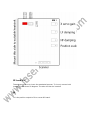
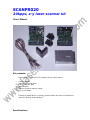
SCANPR020
20kpps, x-y laser scanner kit
User’s Manual
Kit contents:
Please verify your scanner kit contains as per picture above:
•
•
•
•
•
•
X and Y scanner
Scanner mounting block
X and Y scanner amp
power supply
2 driver board to scanner cables
4 by 3 pin cables
If anything listed above is missing, please contact the place of purchase to
have the missing items replaced.
Specifications:
•
•
•
•
•
•
•
•
•
Driver’s ship pre-adjusted (plug and play!)
closed loop scanning system with optical feedback
mirror size 5 x 10mm
power supply input voltage 90-265VAC
Damping, servo gain size trimpots per channel
Compact driver board, 80 x 80 x 40mm
40º max optical scan angle
Mirror reflectivity >90%
Signal Input Voltage: -5v to +5v differential
Driver connections:
•
•
•
Signal input -5v to +5v differential
Power input +/- 15VDC
Scanner connections via 7pin connector
Assembly
•
•
•
•
•
•
•
Please refer to the diagram on the next page for pinout details of the scanner
driver board. Assembly of the scanner kit is straightforward. Here are a few
tips to aid the constructor.
Mount the scanners, driver board and laser onto a suitable base. See
following pics for how to orientate scanners in mounting block
The driver boards will need to be suitably heatsinked, as it will run warm
during normal operation
Connect the scanners to the driver board using the supplied 7 pin cables.
Match up the serial number of the x scanner to the driver board x-output, and
vise versa for the y scanner.
Connect power to each driver board using 2 of the 4 supplied 3 pin cables.
Cut the plug off one end of the cable and strip the ends. Following the
diagram on the following page, screw the cables into the PSU. A legend on
the top panel of the psu indicates what voltages V1, V2 etc, are. The
drivers are not reverse voltage protected, so a error here will damage
the scan amps.
Power supply connection to your mains supply is made via the screw down
terminals. Please pay careful attention to safety here, and ground the metal
casing of the power supply.
The signal input is ‘differential’. Expected signal input voltage is -5v to +5v
(10V p-p). If using with the program board, you will need to connect the
signal input – to signal ground.
If you are using the program board with these scanners, please refer to the
program board manual for setup and use instructions.
JP1 and JP2
These jumpers serve to invert the associated scanner. To invert, remove both
jumpers, rotate them 90 degrees. The axis will then be inverted.
J4
J4 is the position output to fit to a scan fail board.
Lasershowparts reserves the right not to be responsible for the correctness, completeness or quality of the
information provided. Liability claims regarding damage caused by the use of any information provided,
including any kind of information which is incomplete or incorrect, will therefore be rejected. Specifications
are subject to change without notice.
The contents of this manual, whether in part or full, may not be copied, reproduced or redistributed in any
form without the author’s agreement.
© 2007, Lasershowparts, www.lasershowparts.com
Please send any comments to [email protected] , feedback is appreciated!