1
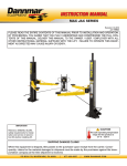
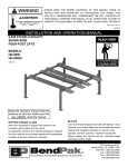
MOHAWK MP-24 SERIES
MOBILE COLUMN LIFT
SPECIFICATIONS
15” & 22” FORK MODEL
1. GENERAL DESCRIPTION
1.1 The purpose of these specifications is to define a mobile wheel contact
lifting system to elevate large buses, trucks, passenger cars, and other
vehicles for the purpose of inspection, maintenance, servicing, and
cleaning.
1.2 A lifting system shall consist of at least one main lifting column and one
secondary column. It shall be possible to form a variety of lifting system
configurations using any combination of main and secondary column pairs.
All column pairs shall be numerically consecutive. For example, columns 1
and 2 are a pair and columns 3 and 4 are a pair. A set of four may consist
of columns 1, 2, 3 & 4. A set of eight may consist of columns 1, 2, 3, 4, 5,
6, 7 & 8. The control system shall allow the flexibility of breaking up sets
to be used as sets of two in geographically separate areas or combining sets
to create a set of up to eight without modifying the electrical system.
Mohawk MP-24 Series
with 15” & 22” Forks
1.3 The lift system shall be approved and certified by the ALI (Automotive Lift
Institute) certification program for automotive lifts and shall meet the
requirements inherent in the testing of the program, including mechanical
as well as electrical testing to ANSI ALI/ALCTV-2006 Standard for
Construction of Automotive Lifts and UL-201 Standard for Garage
Equipment. Proof of certification as well as testing report showing testing at
the certified capacity of the lift must be submitted with bid at the time of
bid. ETL is an ALI sponsored independent nationally recognized testing
laboratory (NRTL) approved by OSHA. (ETL, an independent NRTL,
administers the ALI certification program.)
1.4 The lift system shall be designed to permit combining multiple sets without
modifications to the electrical or mechanical configuration of the lifting
columns. The lift system shall be designed as to be able to handle up to 8
columns in a lifting system (or 192,000 lbs.), with the possibility of
operating one column, one pair or all of the columns together.
1.5 Control cables shall be disconnected from control boxes at both ends of the
cable. Mobile lift systems with control cables “hardwired” into the control
box shall not be acceptable due to the difficulty in replacement and loss of
operating flexibility.
Mohawk MP-24 Series Mobile Column Lift Specifications
Page 1 of 13
1.6 Control cables shall attach to the columns in an open-ended daisy chain
fashion. The opening of the cable loop shall provide access to vehicle entry
into the lifting zone without having to drive over cables. Systems that
incorporate a closed loop cable system that encourage the operators to drive
over control cables are not acceptable.
1.7 Columns shall be structurally designed as to have motor and hydraulic
pump assemblies positioned at the bottom of the column to promote greater
stability while moving the column. Lift systems with motors mounted on
the top of the column shall not be accepted due to their inherent topheaviness and possibility of tipping while moving.
1.8 Each column shall be equipped with a 2 ½ HP TEFC motor of North
American Manufacturer. The motor shall be available in
208/230/440/460/480 or 575 VAC, 3 Phase, 60 HZ. (Note: Only 440480/575 VAC is available for 8 column units) Motor bearings shall be
sealed for life and pre-lubricated for a minimum of 5 years use.
1.8.1 The motors shall be available in 208-230 VAC, Single Phase, 60 Hz as
an option.
1.9 The floor pressure requirements for each column shall not be greater than
70 psi to ensure stability. Lifts which, when loaded, have weight on the
wheels are not acceptable.
1.10 The lift shall be suitable for indoor use on any level service that meets the
loading requirements stated above.
1.11 The lift maintenance shall be limited to monthly and yearly visual checks
to insure that the hydraulic fluid levels are correct and that lift safety
systems are functioning properly.
2. LIFTING CAPACITY
2.1 When specified with 15 inch long lifting forks: Each lifting column shall
have a nominal rated capacity of 24,000 lbs. per column; 48,000 lbs. per
pair, or 96,000 lbs. per set of four; or 144,000 lbs. per set of six columns; or
192,000 lbs. per set of eight columns. One pair of columns, rated at 48,000
lbs, must be capable of lifting the heavy rear ends of customer’s heaviest
vehicle axle. Vehicles weighing more than 48,000 lb on the rear axle
require an additional pair of columns, or heavier rated columns.
2.2 When specified with 22 inch long lifting forks: Each lifting column shall
have a nominal rated capacity of 22,000 lbs. per column; 44,000 lbs. per
pair, or 88,000 lbs. per set of four; or 132,000 lbs. per set of six columns; or
176,000 lbs. per set of eight columns. One pair of columns, rated at 44,000
lbs, must be capable of lifting the heavy rear ends of customer’s heaviest
vehicle axle. Vehicles weighing more than 44,000 lb on the rear axle
require an additional pair of columns, or heavier rated columns.
Mohawk MP-24 Series Mobile Column Lift Specifications
Page 2 of 13
2.3 Combinations of 15 inch and 22 inch long lifting fork columns shall be
available. For example, a four column lift may consist of two front columns
with 15 inch long lifting forks (rated 48,000 lbs each) and two rear columns
with 22 inch long lifting forks (rated 44,000 lbs each) for a system that is
rated 92,000 lbs total. Various other combinations are available.
3. LIFTING HEIGHT
3.1 The lifting height of each fork shall be no less than 67 inches as measured
from the ground to the bottom of the lifting fork (stroke).
4. LIFTING SPEED
4.1 The lifting speed shall not be less than 26 inches per minute either in the
ascent or descent mode. This equates to 155 seconds for a full stroke.
5. CONSTRUCTION
5.1 Upright frame shall be constructed of 1 inch thick by 7 1/4 wide, high
strength R34 fork lift mast channels to ensure structural integrity and
provide a smooth lift guidance system. Forks shall be braced at a minimum
of 3 times along the length of the post to resist channel spreading/bowing
when loaded. Formed steel and I-beam construction columns shall not be
acceptable as they do not afford the required strength and rigidity.
5.2 The base shall be of a rectangular design with square rear corners, which
contact the garage floor when raising a vehicle, so as to provide maximum
rigidity, stability and balance during lifting operation. Lifts which, when
loaded, have weight loaded on the wheels are not acceptable. Lifts which,
when loaded, have weight loaded on small 12” x 12” area column bases
only are not acceptable.
5.3 Columns shall have multiple covers to allow access to the mechanical lock
mechanism, the sensing connection to the carriage, and rear access to the
hydraulic lines at the cylinder.
5.4 To Promote Horizontal and Lateral Stability Individual Column
Dimensions Should Measure:
5.5.1 Base width - 57 inches
5.5.2 Base length – 61 1/2 inches (from outside of pallet jack to end of
column “feet”)
5.5.3 Column Height with carriage in low position – 108 1/2 inches max
5.5.4 Column Height with carriage in high position - 142 1/4 inches max
Mohawk MP-24 Series Mobile Column Lift Specifications
Page 3 of 13
5.6
Lifting Carriage:
5.6.1
Lifting carriage shall ride on maintenance free, double sealed, self
lubricating steel barrel-type bearing rollers. Nylon rollers or sliding
blocks shall not be accepted because they have a higher coefficients of
friction resulting in a higher working pressures for the hydraulic
system, and thus, shorter life expectancy on the power units. Ball-type
bearings shall not be accepted because their axial load ratings are not
as high as barrel-type bearings. Each carriage shall incorporate 8
channel bearings.
5.6.2
Side load slide blocks shall be provided on the carriages to resist
offset loading of the columns. These slide blocks must be accessible
and replaceable from outside of the column without having to remove
the carriage. Any carriage design that requires removal of the carriage
to replace the lifting slide blocks is not acceptable.
5.6.3
The distance between the wheel contact forks shall be hand adjustable
from 11 1/2 inches to 28 inches. Wheel contact forks shall freely
accept tire sizes between R10 and R22.5 inclusively, thereby
accommodating vehicles with up to 53 inch diameter tires (Hemmitt
Tires) and 24 inch rims. Wheel reducer sleeves (sleeve adaptors) shall
not be acceptable as they may slip off of the lifting forks causing a
vehicle to fall.
5.6.4
Standard fork length shall be no less than 15 inches, to accommodate
flotation tires.
5.6.4.1 Alternately 22 inch long lifting forks are available to support dual
inside and outside tires on dual wheeled axles or to accommodate
super single tires. If 22 inch fork length is required, column capacity
is reduced from 24,000 lbs. to 22,000 lbs.
5.6.5
Forks shall be wedge shaped with an angle not to exceed 35 degrees.
This enables the forks to be adjusted closer and support the hub in the
case of a flat tire. Forks with angles exceeding 35 degrees are not
acceptable, due to difficulty of positioning the columns.
5.6.6
The clearance between the lifting column and the back of fork shall be
no less than 9 inches, for operating a single column when lowering
onto a jack stand.
5.6.7
Carriage shall have 1/8 inch minimum clearance from the floor when
in the low position, to facilitate moving the column when power is
cut-off.
Mohawk MP-24 Series Mobile Column Lift Specifications
Page 4 of 13
6. PALLET JACK MECHANISM
6.1 The lifting columns shall be easily moved by one small person using a
pallet jack system with two spring loaded front wheels consisting of at least
6 inch diameter aluminum core with polyurethane tread and straight
bearings and dual 6 5/8 diameter thermo set resin coated steering wheels at
the rear of the jack. The rise of the pallet jack shall be 1 ½ inches
minimum. Smaller wheels, single rear wheels, solid steel or plastic wheels
that do not allow easy column movement and will not be considered due to
difficulty moving columns over floor expansion seams, cracks, or debris on
shop floor.
6.2 The pallet jack mechanism shall have an OSHA approved loop type handle
and shall be raised and lowered using a three position lever with raise,
lower, and neutral position. T-bar handles are not acceptable since they do
not facilitate proper handling of the mobile column.
6.3 Pallet jack mechanism shall have an overload valve that will automatically
lower the jack if the operator attempts to raise a vehicle with the pallet jack
in the raised position. The overload valve shall be set and sealed at the
factory and adjustable in the field if necessary.
6.4 The pallet jack mechanism shall be rated for a minimum of 5,000 lbs. Yet
the pressure relief setting will cause the column to lower to the floor if
500lbs. of pressure is applied to the lift’s columns.
6.5 The two front wheels shall be spring loaded and shall retract when the lift
column are loaded. This retraction shall cause the columns to bear on the
floor thru steel plates, resulting in evenly dispersed low compression forces
on the floor, not line loads at wheels. Non-retractable wheels that support
the lifted load are not acceptable.
7. CONTROLS
7.1 The various functions of the mobile lifting system shall be controlled from
the control panels on the columns.
7.1.1
All columns and all functions shall be clearly labeled in easy to
understand English and not symbolic functions.
7.2 Lifting system shall be operable from any of the columns.
7.2.1 Each Secondary Control Column Panel shall include:
7.2.1.1 A NEMA 4/4X rated (more stringent than NEMA 12) control
enclosure
7.2.1.2 A green pilot light to indicate that the power is turned on.
7.2.1.3 A red pilot light to indicate a fault in the lift operating system.
Mohawk MP-24 Series Mobile Column Lift Specifications
Page 5 of 13
7.2.1.4
A transformer to convert incoming supply voltage to 110V which
is supplied to the PLC (programmable logic controller).
Transformers shall have primary and secondary fuse protection.
Transformers shall not be located outside of control enclosure. Any
design that locates the transformer outside of the control
enclosures is not acceptable, if the lift’s controls can be exposed to
water.
7.2.1.5 A spring loaded three position operational selector switch for
selecting ALL, PAIR, or SINGLE operation.
7.2.1.6 Two push buttons for UP and DOWN operation.
7.2.1.7 One push button for PARK operation to allow load to sit on the
mechanical safety locks.
7.2.1.8 One push button for RESET operation to re-establish a level
condition in the post system.
7.2.1.9 A PLC to monitor the proper operation of the lift and provide
motion control. The PLC shall supply 24VDC to the control
circuit. All buttons will only have 24V to them preventing any
operator shock.
7.2.1.10 Green LED lights on PLC to show presence of inputs and outputs
and to aid in fault trouble shooting.
7.2.1.11 Adjustable setting and automatic resetting overload relay to
protect the motor in the event of an overload.
7.2.1.12 Circuit breaker to protect the wires in the event of a short circuit.
7.2.1.13 A red mushroom palm-type emergency stop button to allow
immediate manual shut down of the entire lifting system.
7.2.1.14 Two connection receptacles for control cables coming to and
from control panel.
7.2.2
Each Main panel shall include:
7.2.2.1 All items as specified in the Secondary panels and the following
additional items.
7.2.2.2 A power contactor which controls distribution of power to all
lifting columns after lift setup and cable connections are made.
7.2.2.3 A disconnect switch to control source power. Switch shall be
capable of being locked in the off position for operator safety.
7.2.2.4 A phase loss and phase reverse relay to assure proper presence
phasing of the supply power.
7.2.2.5 A transformer to convert incoming supply voltage to 24VAC
which is supplied to the lift safety logic circuit which determines
proper lift operation and proper cable connections.
7.2.2.6 One power receptacle for incoming power cable.
7.2.2.7 Dust covers to protect electrical and connections when not in use.
7.3 It shall be possible to form a set of lifts using any combination of main and
secondary column pairs. All column pairs shall be numerically consecutive.
For example, columns 1 and 2 are a pair and columns 3 and 4 are a pair. A
set of four may consist of columns 1, 2, 3, and 4. The control system shall
allow the flexibility of breaking up sets to be used as sets of two in
Mohawk MP-24 Series Mobile Column Lift Specifications
Page 6 of 13
geographically separate areas or combining sets to create a set of up to eight
without modifying the electrical system.
7.4 Individual operation of each column shall be achieved by simultaneously
turning and holding the spring loaded operation mode selector switch to the
SINGLE position and pressing the UP or DOWN button on that column.
Lifts that use operation mode selector switches that are not spring loaded
shall not be accepted due to the possibility of inadvertent switching by other
operators in the shop.
7.5 Paired column operation shall be achieved by simultaneously turning and
holding the spring loaded operation mode selector switch on either of the
two columns on the axle to the PAIR position and pressing the UP or
DOWN button on the column. Lifts that require a complicated sequence of
pressing reference buttons on multiple columns shall not be accepted.
7.6 Paired or individual operation shall be permitted at any time during the
lifting cycle. It shall be possible to switch from SINGLE, PAIR, or ALL
operation in any order regardless of the height position of the lifting
carriage.
7.7 The control system shall utilize an off the shelf Siemens brand PLC
(programmable logic controller) to ensure proper operation of the lift. The
PLC shall have LED lights to indicate inputs and outputs to facilitate
trouble shooting. Printed and dedicated circuit boards, impossible to obtain
from any company except the OEM manufacturer will not be accepted.
7.8 All wiring within electrical enclosures shall be numbered to assist in trouble
shooting. Units with un-numbered wires are not acceptable.
7.9 At 220V, 3 phase, the lift system shall not draw more than 22 Amps per
pair of columns, 44 Amps for a set of 4 columns, 66 Amps for a set of 6
columns.
7.10 A power cable of type SOW, 6 gauge minimum wire with a minimum of
25 feet shall be supplied. Cable shall have a female plug end that can be
connected to any of the main columns.
7.11 One communication control cable shall be supplied per column. These
cables shall have female plugs on both ends. Cables shall be safety OSHA
yellow. Mobile lift systems with control cables “hardwired” into the control
box shall not be acceptable due to the difficulty in replacement and loss of
operating flexibility.
7.12 Level and height sensing of each column shall be achieve by use of a
NEMA 4 potentiometer or linear transducer. Height sensing by use of a
proximity sensor or other means that use a chain or timing belt linkage
system shall not be acceptable due to the susceptibility of failure and misadjustment of these systems.
Mohawk MP-24 Series Mobile Column Lift Specifications
Page 7 of 13
7.13 Male connection ports for power entry and communication cable entry
shall be equipped with snap-shut covers to prevent dirt, dust and water
entry.
7.14 Communication between columns must take place via OSHA safety
colored yellow communication cables. Due to static electricity and/or
vehicle emergency band radio signals, columns that communicate via
”wireless” system are not acceptable.
8. DRIVE MECHANISM
8.1 The drive mechanism shall be hydraulic drive and shall permit lifting
without any pulsation, jerks, or unsteady lifting. Lifting shall be smooth.
8.2 Hydraulic system shall comprise an electrically-powered pump, internal
flow control valves, one full speed down valve, one half speed down valve,
and a fluid reservoir. Working pressure at full load shall not exceed 3000
psi.
8.3 Hydraulic power unit shall be from a U.S.A. manufacturer.
8.4 Hydraulic lifting cylinder shall be piston type. Cylinder casing shall be
mounted on the column base and the barrel shall be enclosed in the carriage
to protect it from debris and damage. Chrome hydraulic cylinder rod shall
be 2 1/2 inch diameter minimum. Piston diameter shall be 3 1/2 inch
diameter minimum. Barrel outside diameter shall be 4 1/8 inch diameter
minimum.
8.5 If necessary, the removal and re-installation of the lifting cylinder shall take
place in less than 30 minutes per column. Due to the extensive amount of
time and costs involved in repairing screw drives, screw drive systems are
not acceptable.
8.6 Stainless steel hydraulic tubing with a minimum burst rating of 5:1 shall be
used to contain pressurized hydraulic fluid. Rubber hydraulic hoses are not
acceptable.
8.7 The hydraulic unit shall be equipped with dual lowering and lifting valve
systems for smooth operation and equalization. Lifts with column pairs that
come to a complete start or stop in normal operation (due to unevenly
loaded vehicles) are not acceptable.
8.8 Each hydraulic cylinder shall be equipped with a velocity fuse to prevent
decent in the event of a major leak. Velocity fuses shall be a fitting type that
is easily replaceable. Velocity fuses must be fabricated by a North
American manufacturer that specializes and has several years in experience
in fabricating these safety valves.
Mohawk MP-24 Series Mobile Column Lift Specifications
Page 8 of 13
8.9 Cylinder rods shall be chrome plated for low abrasion conditions, seal life,
and to prevent slip-stick problems.
9. SAFETY DEVICES
9.1 Each column shall have an automatic multi-position mechanical locking
system. This system shall incorporate a spring loaded latch that will
automatically engage whether the lift is in operation or not. The column
shall have a minimum of 19 lock positions beginning at the lifting height of
12 inches and spaced every 3 inches for the entire stroke of 67 inches. This
safety device shall be totally independent from the lifting drive system.
Systems that utilize non-load bearing “safety nuts” shall not be approved
since they are integrated with the lifting drive itself.
9.2 The mechanical locking system shall be braced to the post by plates so that
the load is distributed throughout the whole section of the post. Any system
that uses a flat plate that loads into a sheet metal column back is not
acceptable.
9.3 The mechanical lock shall be released by an electric pull solenoid when the
lift is lowering. Pull solenoid shall incorporate a spring when releasing
lock to allow electric solenoid locks to “seat” when energized whether lock
is free or not.
9.4 Each lock shall have a manual pull type override lever to allow the lock to
be manually released so that a vehicle may be lowered in the event of a
power outage. This lever shall be easily accessible without disassembling
any lift components. In an electrical blackout, lifts that take a single person
more than 15 minutes to lower, or require special tools or cranks are not
acceptable.
9.5 The lift shall incorporate a PARK button that allows the loaded carriages to
be fully lowered on the mechanical locks, removing pressure from the
hydraulic systems. Any design that has mechanical locks, which does not
allow the load to be lowered onto the locks is not acceptable.
9.6 The lifting system shall incorporate multiple redundant safety systems. The
lift shall support the vehicle in the event of a mechanical failure, motor
failure, hydraulic failure or loss of electrical service by consisting of
electrical, mechanical and hydraulic safety systems.
9.7 Motive UP and DOWN push buttons shall be of a type requiring pressure
be maintained on the buttons by the operator in order to operate the lifts.
9.8 Thermal overload protection relays shall be provided to protect the motors
against overload.
9.9 Cable hooks shall be provided and made of steel construction to provide
convenient and safe storage of cable when the lift is not in operation.
Mohawk MP-24 Series Mobile Column Lift Specifications
Page 9 of 13
9.10 A pilot light on all control boxes shall indicate when the system is
powered.
9.11 A phase relay shall be provided to automatically deactivate the system in
event of a phase loss or reversal in the power supply.
9.12 A safety logic circuit will be incorporated into the electrical system to
ensure that the lift shall not operate (power up) unless all the control cables
are located properly and all the emergency stop buttons are released.
9.13 A motion control system shall monitor the up and down motion of the
lifting carriages and correct any difference of +/- ½ inch in the travel height
of the carriages. If the difference in speed cannot be corrected, the system
shall fault and stop all the columns when the difference between any lifting
carriages becomes greater than 2 inches.
9.14 A red fault light shall indicate when the system is in the fault mode and
shall provide easy to understand indication as to which fault may have
occurred. Lift faults shall be clear and easy to understand and listed in the
user manual.
9.15 Each control whether it is designated as a main or secondary column
control panel shall have a mushroom type emergency stop switch which
stops the movement of all of the columns. The emergency stop switch must
be palm operated and shall require clockwise motion in order to be
released. These emergency stop switches shall directly cut power to the lift
system and shall not be an input to a secondary controller such as a PLC or
PC. The emergency stop buttons shall not “double” as reset buttons.
9.16 All control voltage shall be no greater than 24 volts.
9.17 In the event of a power outage, emergency manual lowering of posts shall
be made possible by the use of manual lowering valves at each pump and
manual lock release levers. Lift shall be able to be lowered without the use
of tools and accomplished by one technician in less than 15 minutes.
10. WARRANTY
10.1 Manufacturer shall provide a minimum warranty of:
10.1.1 Three years on defective structural parts.
10.1.2 Two years on the hydraulic pump unit (including motor)
10.1.3 Two years on the hydraulic cylinder.
10.1.4 One year on electrical components.
Mohawk MP-24 Series Mobile Column Lift Specifications
Page 10 of 13
11. AVAILABLE OPTIONS
11.0 The following is a list of optional accessories available for the Mohawk’s
Mobile column lifts. These options are available for the 15 inch long fork
models only, unless specifically stated otherwise.
Certified Accessory for
Mohawk MP-24 Series
lifts with 15” Forks.
Certified Accessory for
Mohawk MP-24 Series
lifts with 15” & 22”
Forks.
Listed Product
11.1 Chassis Lifting Beams. In order to raise a framed vehicle by the vehicle’s
frame or jacking points (i.e. school buses) a chassis lifting beam option
shall be available. Chassis lifting beams shall contact each pair of lifting
columns, supported by lifting forks, and allow a vehicle to be lifted from
horizontally sliding contact pads to accommodate a variety of vehicles.
Chassis lifting beam is rated 35,000 lbs. This option shall be approved and
certified by the ALI (Automotive Lift Institute) certification program for
automotive lifts and shall meet the requirements inherent in the testing of
the program, including mechanical testing to ANSI ALI/ALCTV-2006
Standard for Construction of Automotive Lifts.
11.2 All column pairs shall be equipped with a plug-in receptacle to accept a
pendant control. Optional Pendant control shall consist of the controls:
“Up”, “Down” and “Park”. This option shall be approved and certified by
the ALI (Automotive Lift Institute) certification program for automotive
lifts and shall meet the requirements inherent in the testing of the program,
including mechanical as well as electrical testing to ANSI ALI/ALCTV2006 Standard for Construction of Automotive Lifts and UL-201 Standard
for Garage Equipment. This accessory is available for both the 15 inch and
22 inch long fork models.
11.3 Mohawk Models #MJS-4775-18, rated 18,000 lbs, and #MJS-4775-24,
rated 24,000 lbs, jack stands shall be available accessories for use with this
lift. These are stand-alone accessories that are available for use with all of
Mohawk’s lift models. These stands shall include the following features:
•
•
•
•
•
•
•
Jack stand shall be tested by an independent nationally recognized
testing laboratory (NRTL) to comply with the newest requirements of
ASME PALD standard for portable automotive lifting devices.
Support pad shall be 6 inch diameter with rubber surface. Optional 6
inch diameter steel yoke pads shall also be available. Pads shall be
interchangeable.
Pad shall be supported with a minimum of 2 1/2 diameter ACME
threaded rod with a minimum of 8 inches of adjustment.
Center section tube shall be 3 1/2 inch outer diameter and 2 3/4 inner
diameter minimum.
Center section tube shall be spring loaded to assist in height adjustment.
Center section tube shall be supported by base section tube with a 1 inch
minimum diameter hitch pin. Hitch pin and mating cotter pin shall be
attached to jack stand with retaining chains to prevent loss.
Holes in center and base section tubes shall be provided to accommodate
jack heights of 45 inch to 75 inch by 3 inch increments.
Mohawk MP-24 Series Mobile Column Lift Specifications
Page 11 of 13
•
•
•
•
Certified
Accessory for
Mohawk MP-24
Series lifts with
15” & 22” Forks.
Base section tube shall be 4 1/2 inch outer diameter and 3 3/4 inner
diameter minimum.
Base section tube shall be reinforced with three 4 inch x 4 inch x 1/4
inch minimum angles.
Wheels shall be a minimum of 4 inch diameter and spread 17 1/2 inches
(center to center) for stability during movement.
Handle shall have an ergonomic shape with rubber hand grip. No
straight handles or T-bar handles shall be accepted.
11.4 An optional weight gauge shall be available. This weight gauge shall be
attachable to a dedicated pressure port of the hydraulic system of each
column. This weight gauge shall be specifically calibrated to indicate the
weight that is supported at the column it is connected to. The weight gauge
will clearly show the lift operator the weight being raised by each specific
column that the gauge is attached to. To calculate total vehicle weight, a
weight gauge must be attached to each operating column. The weight
gauge, when added to the column, will clearly and easily show weight with
no modification to the existing lift. This accessory is available for both the
15 inch and 22 inch long fork models.
Mohawk MP-24 Series Mobile Column Lift Specifications
Page 12 of 13