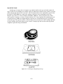
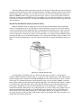
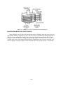
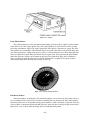
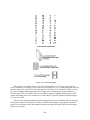
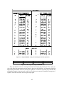
1
NONRESIDENT TRAINING COURSE SEPTEMBER 1998 Navy Electricity and Electronics Training Series Module 22—Introduction to Digital Computers NAVEDTRA 14194 DISTRIBUTION STATEMENT A: Approved for public release; distribution is unlimited. TABLE OF CONTENTS CHAPTER PAGE 1. Operational Concepts ............................................................................................... 1-1 2. Hardware .................................................................................................................. 2-1 3. Software.................................................................................................................... 3-1 4. Data Representation and Communications............................................................... 4-1 APPENDIX I. Glossary.................................................................................................................. AI-1 II. Reference List......................................................................................................... AII-1 INDEX ......................................................................................................................... iii INDEX-1 CHAPTER 1 OPERATIONAL CONCEPTS LEARNING OBJECTIVES Learning objectives are stated at the beginning of each chapter. These learning objectives serve as a preview of the information you are expected to learn in the chapter. The comprehensive check questions placed throughout the chapters are based on the objectives. By successfully completing the Nonresident Training Course (NRTC), you indicate that you have met the objectives and have learned the information. The learning objectives for this chapter are listed below. Upon completion of this chapter, you will be able to do the following: 1. Describe the history of computers. 2. Describe how computers are classified. 3. Explain how digital computers have changed during each generation. 4. Describe the practical applications of digital computers in the Navy. 5. Describe the initial steps needed to use a microcomputer. 6. Explain storage media handling, backups, and the threats to storage media. INTRODUCTION Digital computers are used in many facets of today's Navy. It would be impossible for one NEETS module to cover all the ways they are used in any depth. A few of these ways are covered later in this chapter. The purpose of this module is to acquaint you, the trainee, with the basic principles, techniques, and procedures associated with digital computers. We will use a desktop (personal) computer for most of the examples. Personal computers should be more familiar to you than the large mainframes, and the operating principles of personal computers relate directly to the operating principles of mainframe computers. You will learn the basic terminology used in the digital-computer world. When you have completed these chapters satisfactorily, you will have a better understanding of how computers are able to perform the demanding tasks assigned to them. If we were to define the word computer, we would say a computer is an instrument for performing mathematical operations, such as addition, multiplication, division, subtraction, integration, vector resolution, coordinate conversion, and special function generation at very high speeds. But the usage of computers goes well beyond the mathematical-operations level. Computers have made possible military, scientific, and commercial advances that before were considered impossible. The mathematics involved in orbiting a satellite around the earth, for example, would require several teams of mathematicians for a lifetime. Now, with the aid of electronic digital computers, the conquest of space has become reality. 1-1 Computers are employed when repetitious calculations or the processing of large amounts of data are necessary. The most frequent applications are found in the military, scientific, and commercial fields. They are used in many varied projects, ranging from mail sorting, through engineering design, to the identification and destruction of enemy targets. The advantages of digital computers include speed, accuracy, reliability, and man-power savings. Frequently computers are able to take over routine jobs, releasing people for more important work; work that cannot be handled by a computer. HISTORY OF COMPUTERS The ever increasing need for faster and more efficient computers has created technological advances that can be considered amazing. Ever since humans discovered that it was necessary to count objects, we have been looking for easier ways to do it. Contrary to popular belief, digital computers are not a new idea. The abacus is a manually operated digital computer used in ancient civilizations and used to this day in the Orient (see fig. 1-1). For those who consider the abacus outdated, in a contest between a person using a modern calculator and a person using an abacus, the person using the abacus won. Figure 1-1.—Abacus. The first mechanical adding machine (calculator) was invented by Blaise Pascal (French) in 1642. Twenty years later, an Englishman, Sir Samuel Morland, developed a more compact device that could multiply, add, and subtract. In 1682, Wilhelm Liebnitz (German) perfected a machine that could perform all the basic operations (addition, subtraction, division, and multiplication), as well as extract the square root. Liebnitz's principles are still in use today in our modern electronic digital computers. As early as 1919, electronics entered the scene. An article by W. H. Eccles and F. W. Jordan described an electronic "trigger circuit" that could be used for automatic counting. It was the ECCLES-JORDAN multivibrator which was a little ahead of its time because a trigger circuit is one of many components required to make an electronic digital computer. Modern digital computers use these circuits, known as flip-flops, to store information, perform arithmetic operations, and control the timing sequences within the computer. Under the pressure of military needs in World War II, the science of electronic data processing made giant strides forward. In 1944, Harvard University developed a computing system known as the Automatic Sequence Controlled Calculator. After the initial design and construction, several improved models were built. 1-2 Meanwhile, at the University of Pennsylvania, a second system was being developed. This system, completed in 1946, was named ENIAC (Electronic Numerical Integrator and Computer). ENIAC employed 18,000 vacuum tubes in its circuitry; and in spite of these bulky, hot tubes, it worked quite successfully. The first problem assigned to ENIAC was a calculation in nuclear physics that would have taken 100 human-years to solve by conventional methods. The ENIAC solved the problem in 2 weeks, only 2 hours of which were actually spent on the calculation. The remainder of the time was spent checking the results and operational details. All modern computers have their basics in these two early developments conducted at Harvard University and University of Pennsylvania. In 1950, the UNIVAC I was developed. This machine was usually regarded as the most successful electronic data processor of its day. An outstanding feature of the UNIVAC I was that it checked its own results in each step of a problem; thus eliminating the need to run the problems more than once to ensure accuracy. During the first outbreak of publicity about computers (especially when the UNIVAC predicted the outcome of the 1952 presidential election), the term "giant brain" caused much confusion and uneasiness. Many people assumed that science had created a thinking device superior to the human mind. Currently most people know better. By human standards the giant brain is nothing more than a talented idiot that is wholly dependent upon human instructions to perform even the simplest job. A computer is only a machine and definitely cannot think for itself. The field of artificial intelligence, however, is developing computer systems that can "think"; that is, mimic human thought in a specific area and improve performance with experience and operation. The field of digital computers is still in the growing stages. New types of circuitry and new ways of accomplishing things are continuing to be developed at a rapid rate. In the military field, the accomplishments of digital computers are many and varied. One outstanding example is in weapons systems. Most of the controlling is done by digital computers. CLASSIFICATIONS OF COMPUTERS Computers can be classified in many different ways. They can be classified by the type of technology they use (mechanical, electromechanical, or electronic), the purpose for which they were designed (general purpose or special purpose), by the type of data they can handle (digital or analog), by the amount they cost (from $50 to $10 million and up), and even by their physical size (handheld to room size). We will briefly explain mechanical, electromechanical, and electronic computers; special-purpose and general-purpose computers; and analog and digital computers. MECHANICAL COMPUTERS Mechanical or analog computers are devices used for the computation of mathematical problems. They are made up of components, such as integrators, sliding racks, cams, gears, springs, and driveshafts. Figure 1-2 shows a typical mechanical computer used by the Navy. These computers are analog in nature, and their physical size depends on the number of functions the computer has to perform. In an analog computer, a continuing input will give a constantly updated output. This being perfect for target information, the Navy uses these analog computers primarily for gun fire control. As systems for naval weapons became more and more complex, the need for a different computer was apparent. The functions that had to be performed had increased the size of the computer to an unreasonable scale. 1-3 Figure 1-2.—Bulkhead-type mechanical computer ELECTROMECHANICAL COMPUTERS Electromechanical computers came next and differ from mechanical computers in that they use electrical components to perform some of the calculations and to increase the accuracy. Because the electrical components are smaller than their mechanical counterparts, the size of the computer was reduced, even though it performs more functions. The components used to perform the calculations are devices such as synchros, servos, resolvers, amplifiers, servo amplifiers, summing networks, potentiometers, and linear potentiometers. Figure 1-3 shows one of the Navy's electromechanical computers. These computers are used in gun fire control and missile fire control. Even though they are better than the mechanical computer, they still have their drawbacks. Of prime importance is that they are special-purpose computers. This means they can only be used for one job, dependent on their design characteristics. By today's Navy standards they are still too large, and the maintenance time on them is excessive. The need for a more accurate, reliable, versatile, and smaller computer was recognized. 1-4 Figure 1-3.—Electromechanical computer. ELECTRONIC COMPUTERS Next came electronic computers. The early electronic computers' mathematical processes were solved by using electrical voltages only, applied to elements such as amplifiers, summing networks, differentiating, and integrating circuits. The weak link in this type of electrical computation was the vacuum tube. To correct this, transistors which consume less power and last longer than vacuum tubes were used in the amplifiers. Through technological research and development, we have progressed from tubes, to transistors, to miniaturized circuits, to integrated circuitry. These advances have made it possible to reduce the size and weight of our computers. Figure 1-4 is an example of one of our modern electronic digital computers. 1-5 Figure 1-4.—Electronic digital computer. SPECIAL-PURPOSE COMPUTERS A special-purpose computer, as the name implies, is designed to perform a specific operation and usually satisfies the needs of a particular type of problem. Such a computer system would be useful in weather predictions, satellite tracking, or oil exploration. While a special-purpose computer may have many of the same features found in a general-purpose computer, its applicability to a particular problem is a function of its design rather than to a stored program. The instructions that control it are built directly into the computer, which makes for a more efficient and effective operation. A drawback of this specialization, however, is the computer's lack of versatility. It cannot be used to perform other operations. GENERAL-PURPOSE COMPUTERS General-purpose computers are designed to perform a wide variety of functions and operations. You will probably use this type of computer. A general-purpose computer is able to perform a wide variety of operations because it can store and execute different programs in its internal storage. Unfortunately, having this ability is often achieved at the expense of speed and efficiency. In most situations, however, you will find that having this flexibility makes this compromise a most acceptable one. ANALOG COMPUTERS All analog computers are special-purpose computers. They are designed to measure continuous electrical or physical conditions, such as current, voltage, flow, temperature, length, or pressure. They then convert these measurements into related mechanical or electrical quantities. The early analog computers were strictly mechanical or electromechanical devices. They did not operate on digits (in binary notation, either of the characters, 0 and 1). If digits were involved at all, they were obtained 1-6 indirectly. Your wrist watch (if nondigital); your car's speedometer; and oil pressure, temperature, and fuel gauges are also considered analog computers. The output of an analog computer is often an adjustment to the control of a machine; such as, an adjustment to a valve that controls the flow of steam to a turbine generator or a temperature setting to control the ovens in the ship's galley for baking. Analog computers are also used for controlling processes. To do so, they must convert analog data to digital form, process it, and then convert the digital results back to analog form. You should know that a digital computer can process data with greater accuracy than an analog computer, but an analog computer can process data faster than a digital computer, in some systems. Some computers combine the functions of both analog and digital computers. They are called hybrid computers. DIGITAL COMPUTERS Digital computers perform arithmetic and logic functions on separate discrete data, like numbers, or combinations of discrete data, such as name, rate, and division. This makes them different from analog computers that operate on continuous data, like measuring temperature changes. We generally use digital computers for business and scientific data processing. The following are examples: Accounting—Computers are ideal for keeping payroll records, printing paychecks, billing customers, preparing tax returns, and taking care of many of the other accounting tasks in an organization. Recordkeeping—Computers can record information like inventories and personnel files. They can also keep track of books checked out of a library. Airline ticket counters are much more efficient than they used to be, thanks to centralized reservation computers that can be reached over the telephone lines. Industrial Uses—Industrial computers save considerable time and reduce waste by efficiently performing hundreds of industrial tasks, ranging from filling sales orders and routing parts to various locations on an assembly line, to designing earthquake-resistant structures, and controlling an entire oil refinery. Science—The research and development applications are the most numerous. Digital computers are being used to do lengthy and complicated mathematical calculations millions of times faster than human beings. They are also used to collect, store, and evaluate data from experiments, analyze weather patterns, forecast crop statistics, and, believe it or not, design other computers. Word Processing—Remember, these words were typed into a desktop computer! Word processing is among the most common applications for personal computers. If you have not discovered the advantages of computer writing, it's time to visit a computer dealer for a personalized demonstration. None of this work could be performed by a computer without first instructing the computer how to do it by means of a list of instructions called a program. The instructions in the program must be written in one of the languages the computer understands. The most popular generic term for computer programs is software (this is covered in chapter 3). Hardware (covered in chapter 2), of course, refers to the computer and related equipment. It is easy to say that both computer hardware and software are interdependent because neither can perform useful work without the other. Digital computers may be either special or general purpose. ACCURACY OF COMPUTERS The fundamental difference between analog and digital computers is that digital computers deal with discrete quantities such as beads on an abacus, notches on a toothed wheel, or electrical pulses, while analog computers deal with continuous physical variables such as electrical voltages or mechanical shaft rotations. Computation with analog computers depends on the relation of information to a measurement 1-7 of some physical quantity. For example, you can determine the number of boards in a picket fence by either a digital or an analog system as follows. In the digital method (fig. 1-5, view A), you use an adding machine and count the boards one by one. In the analog method (fig. 1-5, view B), you draw a string (marked off in inches for the width of each board including the gap) over the length of the fence, then measure the length of the string. The number of boards may then be determined by dividing the length of string by the number of inches per board. Figure 1-5A.—Digital computation. Figure 1-5B.—Analog computation. 1-8 The accuracy of an analog computer is restricted to the accuracy with which physical quantities can be sensed and displayed. This, in turn, is related to the quality of the components used in constructing the computer; for example, the tolerance of electrical resistors or mechanical shafts and the quality of the output equipment. In an analog computer, for example, if the constant is represented by a voltage, it probably could be read only to the third decimal place. On the other hand, the accuracy of a digital computer is governed by the number of significant figures carried in the computations. This, in turn, is determined by the computer's design. In a digital computer, the number of decimal places in the constant could be many, depending on the design of the computer processing unit. The digital computer is, therefore, capable of higher precision and accuracy. However, a computer, regardless of its accuracy, would do you no good if the wrong one were chosen for a given task. Most of the computer systems you will work with will be general-purpose digital computers. The remainder of this module will be about general-purpose digital computers. Q-1. How are computers classified? Q-2. Mechanical computers are considered to be of what type? Q-3. The Navy uses analog computers primarily for what purpose? Q-4. How do electromechanical computers differ from the mechanical computers? Q-5. In electronic computers, vacuum tubes were replaced by transistors and transistors have been replaced by what device? Q-6. A computer that is designed to perform a specific operation and usually satisfies the needs of a particular type of problem, is said to be what type of computer? Q-7. Rather than using a stored program, a special-purpose computer's applicability to a particular problem is a function of what? Q-8. What is a drawback to the special-purpose computer? Q-9. A general-purpose computer is designed for what purpose? Q-10. How is a general-purpose computer able to perform different operations? Q-11. In a general-purpose computer, the ability to perform a wide variety of operations is achieved at the expense of what capabilities? Q-12. All analog computers are what type of computers? Q-13. What are analog computers designed to measure? Q-14. Early analog computers were what type of devices? Q-15. What are computers called that combine the functions of both analog and digital computers? Q-16. Digital computers are generally used for what purposes? Q-17. What is the fundamental difference between analog and digital computers? Q-18. How is the accuracy of an analog computer restricted? 1-9 Q-19. A constant represented by a voltage can be read to what decimal place? Q-20. The accuracy of a digital computer is governed by what factor? Q-21. In a digital computer, what does the number of decimal places in the constant depend on? Q-22. You will most likely be working with what type of computer? DIGITAL COMPUTER GENERATIONS In the electronic computer world, we measure technological advancement by generations. A specific system is said to belong to a specific "generation." Each generation indicates a significant change in computer design. The UNIVAC I represents the first generation. Currently we are moving toward the fourth generation. FIRST GENERATION The computers of the first generation (1951-1958) were physically very large machines characterized by the vacuum tube (fig. 1-6). Because they used vacuum tubes, they were very unreliable, required a lot of power to run, and produced so much heat that adequate air conditioning was critical to protect the computer parts. Compared to today's computers, they had slow input and output devices, were slow in processing, and had small storage capacities. Many of the internal processing functions were measured in thousandths of a second (millisecond). The software (computer program) used on first generation computers was unsophisticated and machine oriented. This meant that the programmers had to code all computer instructions and data in actual machine language. They also had to keep track of where instructions and data were stored in memory. Using such a machine language (see chapter 3) was efficient for the computer but difficult for the programmer. Figure 1-6.—First generation computers used vacuum tubes. SECOND GENERATION The computers of the second generation (1959-1963), were characterized by transistors (fig. 1-7) instead of vacuum tubes. Transistors were smaller, less expensive, generated almost no heat, and required very little power. Thus second generation computers were smaller, required less power, and produced a lot less heat. The use of small, long lasting transistors also increased processing speeds and reliability. Cost performance also improved. The storage capacity was greatly increased with the introduction of magnetic disk storage and the use of magnetic cores for main storage. High speed card readers, printers, 1-10 and magnetic tape units were also introduced. Internal processing speeds increased. Functions were measured in millionths of a second (microseconds). Like the first generation, a particular computer of the second generation was designed to process either scientific or business oriented problems but not both. The software was also improved. Symbolic machine languages or assembly languages were used instead of actual machine languages. This allowed the programmer to use mnemonic operation codes for instruction operations and symbolic names for storage locations or stored variables. Compiler languages were also developed for the second generation computers (see chapter 3). Figure 1-7.—Second generation computers used transistors. THIRD GENERATION The computers of this generation (1964-1970), many of which are still in use, are characterized by miniaturized circuits. This reduces the physical size of computers even more and increases their durability and internal processing speeds. One design employs solid-state logic microcircuits (fig. 1-8) for which conductors, resistors, diodes, and transistors have been miniaturized and combined on half-inch ceramic squares. Another smaller design uses silicon wafers on which the circuit and its components are etched. The smaller circuits allow for faster internal processing speeds resulting in faster execution of instructions. Internal processing speeds are measured in billionths of a second (nanoseconds). The faster computers make it possible to run jobs that were considered impractical or impossible on first or second generation equipment. Because the miniature components are more reliable, maintenance is reduced. New mass storage, such as the data cell, was introduced during this generation, giving a storage capacity of over 100 million characters. Drum and disk capacities and speed have been increased, the portable disk pack has been developed, and faster, higher density magnetic tapes have come into use. Considerable improvements were made to card readers and printers, while the overall cost has been greatly reduced. Applications using online processing, real-time processing, time sharing, multiprogramming, multiprocessing, and teleprocessing have become widely accepted. More on this in later chapters. 1-11 Figure 1-8.—Third generation computers used microcircuits. Manufacturers of third generation computers are producing a series of similar and compatible computers. This allows programs written for one computer model to run on most larger models of the same series. Most third generation systems are designed to handle both scientific and business data processing applications. Improved program and operating software has been designed to provide better control, resulting in faster processing. These enhancements are of significant importance to the computer operator. They simplify system initialization (booting) and minimize the need for inputs to the program from a keyboard (console intervention) by the operator. FOURTH GENERATION AND BEYOND The computers of the fourth generation are not easily distinguished from earlier generations, yet there are some striking and important differences. The manufacturing of integrated circuits has advanced to the point where thousands of circuits (active components) can be placed on a silicon wafer only a fraction of an inch in size (the computer on a chip). This has led to what is called large scale integration (LSI) and very large scale integration (VLSI). As a result of this technology, computers are significantly smaller in physical size and lower in cost. Yet they have retained large memory capacities and are ultra fast. Large mainframe computers are increasingly complex. Medium sized computers can perform the same tasks as large third generation computers. An entirely new breed of computers called microcomputers (fig. 1-9) and minicomputers are small and inexpensive, and yet they provide a large amount of computing power. 1-12 Figure 1-9.—Fourth generation desktop (personal) computer. What is in store for the future? The computer industry still has a long way to go in the field of miniaturization. You can expect to see the power of large mainframe computers on a single super chip. Massive data bases, such as the Navy's supply system, may be written into read-only memory (ROM) on a piece of equipment no bigger than a desktop calculator (more about ROM in chapter 2). The future challenge will not be in increasing the storage or increasing the computer's power, but rather in properly and effectively using the computing power available. This is where software (programs such as assemblers, report generators, subroutine libraries, compilers, operating systems, and applications programs) will come into play (see chapter 3). Some believe developments in software and in learning how to use these extraordinary, powerful machines we already possess will be far more important than further developments in hardware over the next 10 to 20 years. As a result, the next 20 years (during your career) may be even more interesting and surprising than the last 20 years. Q-23. Technological advancement is measured by what, in the electronic computer world? Q-24. What does each generation of computer systems indicate? Q-25. What were computers of the first generation characterized by? Q-26. How did vacuum tubes cause a problem for first generation computers? Q-27. In first generation computers, internal processing functions were measured by what division of time? Q-28. The software (computer program) used on first generation computers was what type? Q-29. How were processing speed and reliability increased in second generation computers? Q-30. In second generation computers, how was the storage capacity greatly increased? Q-31. With improvements in software, what kind of computer languages could be used on second generation computers? 1-13 Q-32. What do the smaller circuits in third generation computers allow for? Q-33. On third generation computers, what results are gained by faster internal processing speeds? Q-34. The data cell had a storage capacity of how many characters? Q-35. What type of applications were most third generation computer systems designed to accomplish? Q-36. What type of computers are small and inexpensive yet provide a lot of computing power? Q-37. What does the acronym ROM stand for? Q-38. What will be one of the future challenges involving computer power? Q-39. What term is used for programs such as assemblers, compilers, and operating systems? USES OF A DIGITAL COMPUTER In the modern computer world of today, the uses of the digital computer are almost as limitless as a person's imagination. New and better programs are being written everyday for easier and greater uses. Consider how many mathematicians it would take to put an astronaut in orbit around the moon, but it only takes one computer. Think back to the days without word processing when a document had to be retyped entirely when any changes were needed. Think back to the days of using an adding machine to prepare and revise budgets and accounting reports. Let's look at three of the primary uses of general-purpose digital computers in the Navy: word processing, accounting/recordkeeping, and work center uses. WORD PROCESSING One of the more widespread uses of the computer is word processing. The word processor can be considered a typewriter with a display screen. To the hundreds of thousands of word processor users, the computer is nothing more than a typewriter. Both have keyboards, and both have a mechanism for making the image of the character you strike on the keyboard appear on some type of visual medium. When using an electric typewriter, the process is strictly mechanical. When you press the key, it causes the type face to strike the paper, and in so doing, it leaves an impression. In the computer, the process is more indirect. A program stored in the computer's memory causes a visual representation to appear on a crt (cathode-ray tube) or at a printer. However, from the view point of the user, the result is the same, a printed document. The great advantage of computers over typewriters is in correcting errors. In the past, correcting a document with a typewriter has meant typing it all over again. Since computers allow the movement of information from one part of memory to another, it is possible to make many changes on a document, and print the result. If the document is still not correct, only the changes need to be entered. The use of computers in this particular way came to be known as word processing. A further breakthrough came with the development of word-processing application programs for microcomputers. These programs cost a fraction of their office machine counterparts, and could be run on general-purpose microcomputers. This was unique because general-purpose microcomputers could be used for functions such as spreadsheets, data base management systems, and programming in common computer languages. The Navy saw the obvious uses to which microcomputers using the word processing programs could be put. Some of these are manuscript writing, memorandum writing, identification-card application filing, and recordkeeping. 1-14 ACCOUNTING AND RECORDKEEPING There are virtually unlimited applications for the computer in today's modern business world, from basic accounting functions to controlling the manufacture of products, and of course, keeping records of these actions. Six standard systems dealing with accounting applications are widely accepted. These systems are (1) order entry; (2) inventory control; (3) accounts receivable; (4) accounts payable; (5) general ledger; and (6) payroll. (Figure 1-10 shows a simplified flowchart of payroll.) The area of recordkeeping has two requirements, legal and audit. The Navy has included similar functions in its Shipboard Non-Tactical ADP Program for work center use. Figure 1-10.—Programming flowchart used to build a payroll program. WORK CENTER USES (SNAP II) Every Navy rating has the responsibility for some element of ship's maintenance. And for every rate, recordkeeping has been a "tough nut to turn," an administrative chore that goes along with the work to be done, but takes a "back burner" position to the physical maintenance of the ship and equipment. Today, aboard some ships and soon aboard most, much of that hassle will be done with a SNAP. 1-15 The Navy has looked at the paperwork blizzard of recordkeeping responsibility of the essential records and reports that must be generated, and has offered relief to the fleet. This is in the form of S-N-A-P, which stands for Shipboard Non-Tactical ADP Program. SNAP II is a modern shipboard computer system designed to support shipboard and intermediatelevel maintenance, supply, financial, and administrative functions. If this sounds confusing, it really isn't, for the systems are designed to be user-friendly; that is, operating instructions are written in everyday English. Figure 1-11 shows the AN/UYK-62 (V) Data Processing Set. This is the SNAP II computer and its associated hardware. Figure 1-11.—AN/UYK-62 (V) Data Processing Set (SNAP II). Over the next 3 years, new functions will be added to SNAP to support more of the ship's administrative workload. Pay, personnel, food service, ship's store, PMS, training, medical and dental data are all to be added to SNAP systems. The SNAP concept is to take the power of the modern computer, the ability to process information, and put that power in the hands of the work center sailors. The sailors can use the system to reduce the labor associated with the paperwork function. User terminals are placed in the different work centers for use by the work center supervisor. Each work center has a different access code. This access code or password prevents unauthorized entry into the main computer's program. Different levels of entry are also defined. The levels depend on a work center's need. Information stored in the computer for a typical work center normally has the following items that can be updated by the work center supervisor. COSAL (coordinated onboard ship/shore allowance list) is a listing of the repair parts that are allowed to be kept onboard ship, at all times. APL (allowance parts 1-16 list) is the reference for stock numbers, part numbers, and quantity allowed onboard for a specific system. EIC (equipment identification code) identifies a system, sub-system, or equipment. SHIP'S FORCE WORK LIST is a listing of all work to be performed by a certain work center during a given time period. CSMP (current ship's maintenance projects) provides shipboard maintenance managers with a consolidated listing of deferred maintenance to manage and control its accomplishment. These are but a few of the uses of SNAP II that can be updated by the work center supervisor. Although the information is usually viewed on a display screen (cathode-ray tube), printed (hard) copies can be obtained. Today, hard copy output from SNAP can be sent to higher authorities in lieu of written reports. In the future, these hard copy transmittals may be replaced by disks or tapes containing the same data. In some cases, the shipboard computers will have an extra telephone wire to the pier or tender, and information can be exchanged electronically. And there are other important benefits. In practice, the system expedites the storage and retrieval of information the Navy has about its ships. In turn, information that is more accessible means a more timely supply of parts, an improved aid to planners on when and how long to schedule ships' overhauls, and updated information for making decisions whether to place additional or remove unnecessary shipboard equipment. These decisions are now made by laboriously using stacks of printed files. SNAP can sort through these files electronically so Navy planners can make more effective and timely decisions. SNAP II is a system for unclassified use only at present. This cuts the costs of the installation and many of the physical and electronic security requirements. Q-40. What is one of the more widespread uses of the computer? Q-41. What is the great advantage of computers over typewriters? Q-42. How are word processing programs used by the Navy? Q-43. How many systems dealing with accounting applications have been widely accepted? Q-44. What does the acronym S-N-A-P stand for? Q-45. For what purposes is the SNAP II system designed? Q-46. What does user friendly mean in computer terms? Q-47. What does a password prevent? Q-48. In the SNAP II system, how are the different levels of entry defined? Q-49. The work center supervisor can update what items from a user terminal? Q-50. At present what type of classified use is allowed for SNAP II? USING A DESKTOP COMPUTER To use a desktop (personal) computer effectively, you'll need to learn about the hardware (the equipment) and the software (the programs). You will also need to know how to handle disks and how to back up programs and data files. So let's assume you have a desktop computer system to use. Its hardware consists of a display screen, a keyboard, a computer, two floppy disk drives (A & B), and a printer. Look at the example in figure 1-12. You need software (computer programs) to make the computer operate. The 1-17 first program you need is the operating system. The operating system manages the computer and allows you to run application programs like word processing or recordkeeping programs. So let's begin with the operating system. Figure 1-12.—Typical microcomputer system with display, keyboard, floppy disk drives, and printer. OPERATING SYSTEM An operating system is simply a set of programs and routines that lets you and other programs use the computer. A digital computer uses one central set of programs called the operating system to manage execution of other programs and to perform common functions like read, write, or print. Other programs, or you the user, can order the operating system to perform these common functions. These orders are called system calls when other programs use them, or simply commands when you put them through the keyboard. First, you must load the operating system into the computer so we, and our programs, can use the computer. Remember, in our example, we have a desktop computer with two floppy disk drives, named A and B. Booting the System Each desktop computer has a built-in program called "bootstrap loader." When you turn the computer on, this program tries to load, or "boot," an external operating system from disk, usually from drive A, into the computer's internal memory. Disk drive B is usually used for data file disks. The term boot comes from the idea of pulling yourself up by your bootstraps. The computer loads a little program from the disk that tells it how to load a second, bigger program (the operating system). The operating system then tells it how to load another program (an applications program or utility program) to perform a specific job or function. The first thing you need to learn about using a computer is that computers and their programs are very particular. They require complete accuracy and attention to detail on your part. They are not good at guessing what you meant. You'll quickly learn there are a few things that can go wrong at this point, in which case the computer will give you an error message on the display screen similar to this: Device Error 1-18 This means the computer is not reading anything in A drive. Check for: 1. No floppy disk in drive A 2. Floppy disk inserted incorrectly in drive 3. Lock handle on drive A not lowered Another error message you might receive at this time is: No System This means the computer is reading a properly inserted floppy disk, but the disk does not have an operating system on it. Replace the disk with one that does contain the operating system. Once the operating system is properly booted (loaded), you will see a display similar to this: A> You now have what is called a prompt. At this point you can tell the computer what to do next, such as run an application program for example: word processing, accounting, or recordkeeping. Running an Application Program To load an application program into the computer from drive A, you put the disk with the application program in disk drive A. Next you type the name of the program following the operating system prompt (A>). A>WORDPROC This tells the system what program to load and run; in this case Word Processing. The computer then does what the application program tells it. If the application is word processing, the system is ready for you to type a new document, correct an existing document, print a document, and so on. You'll learn more about both the operating system and application programs in chapter 3. Each application program will have its own set of instructions to follow. In addition to printed documentation, many will include online HELP screens you can display while you are working. These will tell you how to perform a given function or operation. Another area that needs your constant attention relates to handling floppy disks and making backup copies to be sure your work is not lost. STORAGE MEDIA HANDLING AND BACKUP Floppy disks (fig. 1-13) are one means by which you will store data (files that you create) either directly or in backing up the data you store on hard (or fixed) disk. For this reason, and because floppy disks are extremely fragile, you should follow certain guidelines to ensure their proper care and handling. This includes properly labeling and backing up disks. 1-19 Figure 1-13.—Floppy disk. Handling Never touch the exposed surface of a disk. As you know (or will learn), most of the surface of the actual disk is protected most of the time; however, there are areas that are exposed. These areas are the timing hole and the read/write slots. Touching an exposed area can ruin that particular area. If you are familiar with Murphy's Law, you will realize the area you ruin will invariably contain the most important data on that disk. Storage Never bend, fold, or otherwise distort the shape of a disk. Never place heavy objects such as books on top of disks. Store disks in the box they came in, or in filing containers that are specifically designed for storing disks. Try to store disks vertically, but if you do store disks horizontally, do not stack more than 10 disks. Exposure Disks are subject to exposure from magnetic fields, smoke, heat, and sunlight. X-rays may also have a negative effect. MAGNETIC FIELDS.—Disks should never be exposed to anything that could be the source of a magnetic field. Exposure of a disk to a magnetic field could cause the destruction of some or all of the data contained on that disk. Some common sources of magnetic energy are crt's, disk drives, and perhaps the most common, the telephone. SMOKE.—Smoke can cause buildup on disks and on disk drives. DO NOT SMOKE while you work at a terminal or computer. 1-20 HEAT AND SUNLIGHT.—Never expose disks to excessive heat or direct sunlight. Either can cause the disks to become warped or distorted so they cannot be used. Disks are made of a plastic material, and if you have ever seen a phonograph record that has been exposed to heat or sunlight, you have some idea of the damage that can result from exposure. Typically, disks will operate only between 10 and 50 degrees Celsius (50 to 120 degrees Fahrenheit). They will accept a relative humidity of 10% to 80%. X-RAYS.—There is some question about the effect that airport x-ray machines have on disks. It has been the normal experience that the walk-through x-ray machines at airports have no effect on floppy disks; however, this is not to say there will be no effect. It is up to you because these disks contain the data you work with and need. You may not want to take the chance the disks will be affected. Labeling When labeling the outside of a floppy disk, write the label before attaching it to the disk. Never use a pencil or ballpoint pen to write on a label once that label has been attached to a disk. When you use an instrument with a sharp point to write on the label, you can actually etch into the surface of the disk underneath the protective sheath, thereby destroying that disk. If you must write on a label once it has been attached to a disk, use a felt-tip marker. Data Backup In virtually all computer systems, the possibility exists for errors to occur that accidentally alter or destroy the data stored in the data bases or files. This may occur because of natural disasters, such as fire, flood, or power outages. It may occur through operator error. It may occur through equipment malfunction. It is essential, therefore, to provide a means to ensure that any data lost can be recovered. The most common method is backup files. A backup file is merely a copy of a file. If for some reason the file or data base is destroyed or becomes unusable, the backup file can be used to recreate the file or data base. Two media are commonly used for backup: disk or tape. Disk—The most common method of creating a backup for a microcomputer is to use a floppy disk and the diskcopy procedure. This is accomplished by using the original data base or file and copying the information onto a blank floppy disk. The instructions for this procedure will be provided with the particular computer and program you are using. Tape—Another method of creating a backup is to use magnetic tape. The information contained on your disk, whether it is a data base or file, can be copied onto a tape. The instructions for this procedure will also be provided with the particular computer and program you are using. Q-51. What is a central set of programs called that manages the execution of other programs and performs common functions like read, write, and print? Q-52. What is the function of a built-in program called a bootstrap loader? Q-53. When you see the error message NO SYSTEM, what does it mean? Q-54. When an operating system prompt (A>) is displayed on the screen, what do you enter from the keyboard to load an application program? Q-55. If disks are stored horizontally, how many can be stacked? Q-56. What can exposure to a magnetic field do to the data on a disk? 1-21 Q-57. What is the temperature range within which a disk will operate? Q-58. What is the most common method to ensure that any stored data lost can be recovered? Q-59. The most common method of creating a backup for a microcomputer is what? Q-60. Other than disk, what is another media used for backup files? SUMMARY This chapter has presented information on the history and classification of computers. It introduced you to electronic digital computers, their uses and operation. The information that follows summarizes the important points of this chapter. Early computers were MECHANICAL or ELECTROMECHANICAL. ELECTRONIC COMPUTERS came into use in the 1940s. ANALOG COMPUTERS are special-purpose computers designed to measure continuous electrical or physical conditions. DIGITAL COMPUTERS are special- or general-purpose computers designed to perform arithmetic and logic functions on separate discrete data. They are generally used for business and scientific data processing. Digital computers have evolved through four generations: vacuum tubes, transistors, miniaturized circuits, and integrated circuits. WORD PROCESSING is one of the most widespread uses of desktop computers. ACCOUNTING AND RECORDKEEPING are also major uses of computers. Included are order entry, inventory control, accounts receivable, accounts payable, general ledger, and payroll. The Navy's SHIPBOARD NON-TACTICAL ADP PROGRAM (SNAP) consists of computers used by work center supervisors for logistic and administrative support. This system expedites the storage and retrieval of information the Navy has about its ships. A DESKTOP (PERSONAL) COMPUTER is a microcomputer with at least a display screen, keyboard, floppy disk drive, and printer. It may also have additional devices such as a second floppy or a hard disk drive. An OPERATING SYSTEM is loaded into the computer to let you and other programs use the computer. It also provides common functions like read, write, and print. You can direct the computer to run an APPLICATION PROGRAM by telling the operating system the name of program to run. Common application programs are word processing, accounting, and recordkeeping. You will probably be using FLOPPY DISKS for data storage and backup. To ensure you don't damage a disk, use care in handling, labeling and storing the disks. 1-22 ANSWERS TO QUESTIONS Q1. THROUGH Q60. A-1. Technology (mechanical, electromechanical, electronic), purpose (special or general), type of data they handle (analog or digital), cost, physical size (handheld to room size). A-2. Analog. A-3. Gun fire control. A-4. Electromechanical computers use electrical components to perform some of the calculations. A-5. Integrated circuits. A-6. Special-purpose. A-7. Its design. A-8. Lack of versatility. A-9. To perform a wide variety of functions and operations. A-10. By storing different programs in its internal storage. A-11. Speed and efficiency. A-12. Special-purpose. A-13. Continuous electrical or physical conditions. A-14. Mechanical or electromechanical. A-15. Hybrid computers. A-16. Business and scientific data processing. A-17. Digital computers deal with discrete quantities, while analog computers deal with continuous physical variables. A-18. By the accuracy with which physical quantities can be sensed and displayed. A-19. Third. A-20. The number of significant figures carried in the computations. A-21. Design of the computer processing unit. A-22. General-purpose digital computer. A-23. Generations. A-24. Significant change in computer design. A-25. The vacuum tube. A-26. They were unreliable, required a lot of power to run, and produced so much heat that air conditioning was needed to protect computer parts. 1-23 A-27. Thousandths of a second (millisecond). A-28. Unsophisticated and machine oriented. A-29. By the use of small, long lasting transistors. A-30. With the introduction of magnetic disk storage and the use of core for main storage. A-31. Symbolic machine languages or assembly languages. A-32. Faster internal processing speeds. A-33. Faster execution of instructions. A-34. Over 100 million. A-35. Both scientific and business data processing applications. A-36. Microcomputers and minicomputers. A-37. Read-only memory. A-38. How to properly and effectively use the computing power available. A-39. Software. A-40. Word processing. A-41. Correcting errors. A-42. For manuscript writing, memorandum writing, identification-card application filing, and recordkeeping. A-43. Six. A-44. Shipboard Non-tactical ADP Program. A-45. To support shipboard and intermediate level maintenance, supply, financial, and administrative functions. A-46. Operating instructions are written in everyday English. A-47. Unauthorized entry into the main computer's program. A-48. Dependent on a work center's need. A-49. COSAL, APL, EIC, SHIP'S FORCE WORK LIST, and CSMP. A-50. Unclassified. A-51. Operating system. A-52. To load an external operating system into the computer's internal memory. A-53. The computer is reading a properly inserted floppy disk, but it does not have an operating system on it. 1-24 A-54. The program name. A-55. No more than ten. A-56. Destroy some or all of it. A-57. 10 to 50 degrees Celsius or 50 to 120 degrees Fahrenheit. A-58. Backup files. A-59. Use a floppy disk and the diskcopy procedure. A-60. Magnetic tape. 1-25 CHAPTER 2 HARDWARE LEARNING OBJECTIVES Upon completion of this chapter, you will be able to do the following: 1. Explain the cpu and describe the functions of the different sections. 2. Categorize the types of storage and their functions. 3. Describe how storage is classified. 4. Analyze and compare the input/output devices and explain their functions. INTRODUCTION Components or tools of a computer system are grouped into one of two categories, hardware or software. We refer to the machines that compose a computer system as hardware. This hardware includes all the mechanical, electrical, electronic, and magnetic devices within the computer itself (the central processing unit) and all related peripheral devices (printers, magnetic tape units, magnetic disk drive units, and so on). These devices will be covered in this chapter to show you how they function and how they relate to one another. Take a few minutes to study figure 2-1. It shows the functional units of a computer system: the inputs, the central processing unit (cpu), and the outputs. The inputs can be on any storage medium from punched cards, paper tape, or magnetic ink to magnetic tape, disk, or drum; or they can be entries from a console keyboard or a cathode-ray tube (crt) terminal. The data from one or more of these inputs will be processed by the central processing unit to produce output. The output may be in punched cards or paper tape, on magnetic tape, disk, or drum, or it may be printed reports or information displayed on a console typewriter or crt terminal. The figure also shows the data flow, instruction flow, and flow of control. We'll start our hardware discussion with the cpu and then move into storage media (disk, tape, and drum). We'll end the chapter with a discussion of input/output devices and how they work. CENTRAL PROCESSING UNIT (CPU) The brain of a computer system is the central processing unit, which we generally refer to as the cpu or mainframe. The central processing unit IS THE COMPUTER. It is the cpu that processes the data transferred to it from one of the various input devices, and then transfers either the intermediate or final results of the processing to one of many output devices. A central control section and work areas are required to perform calculations or manipulate data. The cpu is the computing center of the system. It consists of a control section, internal storage section (main or primary memory), and arithmetic-logic section (fig. 2-1). Each of the sections within the cpu serves a specific function and has a particular relationship to the other sections within the cpu. 2-1 Figure 2-1.—Functional units of a computer system. CONTROL SECTION The control section may be compared to a telephone exchange because it uses the instructions contained in the program in much the same manner as the telephone exchange uses telephone numbers. When a telephone number is dialed, it causes the telephone exchange to energize certain switches and control lines to connect the dialing phone with the phone having the number dialed. In a similar manner, 2-2 each programmed instruction, when executed, causes the control section to energize certain control lines, enabling the computer to perform the function or operation indicated by the instruction. The program may be stored in the internal circuits of the computer (computer memory), or it may be read instruction-by-instruction from external media. The internally stored program type of computer, generally referred to only as a stored-program computer, is the most practical type to use when speed and fully automatic operation are desired. Computer programs may be so complex that the number of instructions plus the parameters necessary for program execution will exceed the memory capacity of a stored-program computer. When this occurs, the program may be sectionalized; that is, broken down into modules. One or more modules are then stored in computer memory and the rest in an easily accessible auxiliary memory. Then as each module is executed producing the desired results, it is swapped out of internal memory and the next succeeding module read in. In addition to the commands that tell the computer what to do, the control unit also dictates how and when each specific operation is to be performed. It is also active in initiating circuits that locate any information stored within the computer or in an auxiliary storage device and in moving this information to the point where the actual manipulation or modification is to be accomplished. The four major types of instructions are (1) transfer, (2) arithmetic, (3) logic, and (4) control. Transfer instructions are those whose basic function is to transfer (move) data from one location to another. Arithmetic instructions are those that combine two pieces of data to form a single piece of data using one of the arithmetic operations. Logic instructions transform the digital computer into a system that is more than a high-speed adding machine. Using logic instructions, the programmer may construct a program with any number of alternate sequences. For example, through the use of logic instructions, a computer being used for maintenance inventory will have one sequence to follow if the number of a given item on hand is greater than the order amount and another sequence if it is smaller. The choice of which sequence to use will be made by the control section under the influence of the logic instruction. Logic instructions, thereby, provide the computer with the ability to make decisions based on the results of previously generated data. That is, the logic instructions permit the computer to select the proper program sequence to be executed from among the alternatives provided by the programmer. Control instructions are used to send commands to devices not under direct command of the control section, such as input/output units or devices. ARITHMETIC-LOGIC SECTION The arithmetic-logic section performs all arithmetic operations-adding, subtracting, multiplying, and dividing. Through its logic capability, it tests various conditions encountered during processing and takes action based on the result. As indicated by the solid arrows in figure 2-1, data flows between the arithmetic-logic section and the internal storage section during processing. Specifically, data is transferred as needed from the internal storage section to the arithmetic-logic section, processed, and returned to the internal storage section. At no time does processing take place in the storage section. Data may be transferred back and forth between these two sections several times before processing is completed. The results are then transferred from internal storage to an output unit, as indicated by the solid arrow (fig. 2-1). 2-3 MEMORY (INTERNAL STORAGE) SECTION All memory (internal storage) sections must contain facilities to store computer data or instructions (that are intelligible to the computer) until these instructions or data are needed in the performance of the computer calculations. Before the stored-program computer can begin to process input data, it is first necessary to store in its memory a sequence of instructions, and tables of constants and other data it will use in its computations. The process by which these instructions and data are read into the computer is called loading. Actually, the first step in loading instructions and data into a computer is to manually place enough instructions into memory using the keyboard or electronically using an operating system (discussed in chapter 1), so that these instructions can be used to bring in more instructions as desired. In this manner a few instructions are used to bootstrap more instructions. Some computers make use of an auxiliary (wired) memory that permanently stores the bootstrap program, thereby making manual loading unnecessary. The memory (internal storage) section of a computer is essentially an electronically operated file cabinet. It has a large number (usually several hundred thousand) of storage locations; each referred to as a storage address or register. Every item of data and program instruction read into the computer during the loading process is stored or filed in a specific storage address and is almost instantly accessible. Q-1. What is the brain of a computer system? Q-2. How many sections make up the central processing unit? Q-3. What are the names of the sections that make up the cpu? Q-4. The control section can be compared to what? Q-5. What are the four major types of instructions in the control section? Q-6. What capability allows the arithmetic/logic section to test various conditions encountered during processing and take action based on the result? Q-7. In the arithmetic/logic section, data is returned to what section after processing? Q-8. What is the process by which instructions and data are read into a computer? TYPES OF INTERNAL STORAGE You already know that the internal storage section is the holding area in which instructions and data are kept. For the control section to control and coordinate all processing activity, it must be able to locate each instruction and data item in storage. About now, you are probably wondering how the control section is able to find these instructions and data items. To understand this, let's look at storage as nothing more than a collection of mailboxes. Each mailbox has a unique address and represents a location in memory as shown in figure 2-2. Like the mail in your mailbox, the contents of a storage location can change, but the number on your mailbox or memory address always remains the same. In this manner, a particular program instruction or data item that is held in storage can be located by knowing its address. Some computers can address each character of data in memory directly. Others address computer words which contain a group of characters at a single address. Each computer word contains a group of characters at a 2-4 single address. Some of the more common types of internal storage media used in today's computers are as follows: magnetic core, semiconductor, and bubble. Figure 2-2.—Memory locations. MAGNETIC CORE STORAGE Although magnetic core storage is no longer as popular as it once was, we will cover it in some detail because its concepts are easily understood and apply generally to the more integrated semiconductor and bubble-type memories. Magnetic core storage is made up of tiny doughnut-shaped rings made of ferrite (iron), that are strung on a grid of very thin wires (fig. 2-3). Since data in computers is stored in binary form (refer to NEETS, module 13), a two-state device is needed to represent the two binary digits (bits), 0 for off and 1 for on. In core storage, each ferrite ring can represent a 0 or 1 bit, depending on its magnetic state. If magnetized in one direction, it represents a 1 bit, and if magnetized in the opposite direction, it represents a 0 bit. These cores are magnetized by sending an electric current through the wires on which the core is strung. It is this direction of current that determines the state of each core. Figure 2-3.—Two-state principle of magnetic storage. 2-5 SEMICONDUCTOR STORAGE (THE SILICON CHIP) Semiconductor memory consists of hundreds of thousands of tiny electronic circuits etched on a silicon chip (fig. 2-4). Each of these electronic circuits is called a bit cell and can be in either an off or on state to represent a 0 or 1 bit, depending on whether or not current is flowing in that cell. Another name you will hear used for semiconductor memory chips is integrated circuits (ICs). Developments in technology have led to large scale integration (LSI), which means that more and more circuits can be squeezed onto the same silicon chip. Companies are even manufacturing very large scale integrated circuits (VLSI), which means even further miniaturization. Figure 2-4.—A semiconductor memory chip (integrated circuit). Some of the advantages of semiconductor storage are fast internal processing speeds, high reliability, low power consumption, high density (many circuits), and low cost. However, there is a drawback to this type of storage. It is volatile, which means all data in memory is lost when the power supply is removed. Should the power on your computer fail and you have no backup power supply, all the stored data is lost. This is not the case with magnetic core storage. Core storage is nonvolatile. This means the data is retained even if there is a power failure or breakdown, since the cores store data in the form of magnetic charges rather than electric current. BUBBLE STORAGE One of the latest technological developments in storage media is the introduction of bubble memory. Bubble memory consists of a very thin crystal made of semiconductor material. The molecules of this special crystal act as tiny magnets (fig. 2-5). The polarity of these molecules or "magnetic domains" can be switched in an opposite direction by passing a current through a control circuit imprinted on top of the crystal. In this manner, data can be stored by changing the polarity of the magnetic domains. Since the principle is the same as for magnetic core storage, bubble memory is considered nonvolatile. The data is retained even if there is a power failure. Furthermore, the process of reading from bubble memory is nondestructive, meaning that the data is still present after being read. This is not the case with core storage, which must be regenerated after being read. If we were to view these magnetic domains under a microscope, they would look like tiny bubbles; hence the name, bubble memory. 2-6 Figure 2-5.—Bubble memory. Q-9. Magnetic core storage is made up of what? Q-10. A semiconductor memory consists of what? Q-11. What is another name for semiconductor memory chips? Q-12. In computer storage, what does volatile mean? Q-13. What type of storage can retain its data even if there is a power failure or breakdown? Q-14. Bubble memory consists of what? Q-15. How are the magnetic domains of a bubble memory switched? Q-16. What do we mean when we say that reading from bubble memory is nondestructive? CLASSIFICATIONS OF INTERNAL STORAGE Up to this point, you have learned some of the general functions of the cpu, the physical characteristics of memory, and how data is stored in the internal storage section. Now, we will explain yet another way to classify internal (primary or main) storage. This is by the different kinds of memories used within the cpu: read-only memory, random-access memory, programmable read-only memory, and erasable programmable read-only memory. READ-ONLY MEMORY (ROM) In most computers, it is useful to have often used instructions, such as those used to bootstrap (initial system load) the computer or other specialized programs, permanently stored inside the computer. Memory that enables us to do this without the programs and data being lost (even when the computer is powered down) is called read-only memory. Only the computer manufacturer can provide these programs in ROM and once done, they cannot be changed. Consequently, you cannot put any of your own data or programs in ROM. Many complex functions such as routines to extract square roots, translators for programming languages, and operating systems can be placed in ROM memory. Since these instructions are hard wired (permanent), they can be performed quickly and accurately. Another advantage of ROM is 2-7 that your computer facility can order programs tailored for its needs and have them permanently installed in ROM by the manufacturer. Such programs are called microprograms or firmware. RANDOM-ACCESS MEMORY (RAM) Another kind of memory used inside computers is called random-access memory (RAM) or read/write memory. RAM memory is rather like a blackboard on which you can scribble down notes, read them, and rub them out when you are finished with them. In the computer, RAM is the working memory. Data can be read (retrieved) from or written (stored) into RAM just by giving the computer the address of the location where the data is stored or is to be stored. When the data is no longer needed, you can simply write over it. This allows you to use the storage again for something else. Core, semiconductor, and bubble storage all have random access capabilities. PROGRAMMABLE READ-ONLY MEMORY (PROM) An alternative to ROM is programmable read only memory (PROM) that can be purchased already programmed by the manufacturer or in a blank state. By using a blank PROM, you can enter any program into the memory. However, once the PROM has been written into, it can never be altered or changed. Thus you have the advantage of ROM with the additional flexibility to program the memory to meet a unique need. The main disadvantage of PROM is that if a mistake is made and entered into PROM, it cannot be corrected or erased. Also, a special device is needed to "burn" the program into PROM. ERASABLE PROGRAMMABLE READ-ONLY MEMORY (EPROM) The erasable programmable read-only memory (EPROM) was developed to overcome the drawback of PROM. EPROMs can also be purchased blank from the manufacturer and programmed locally at your command/activity. Again, this requires special equipment. The big difference with EPROM is that it can be erased if and when the need arises. Data and programs can be retrieved over and over again without destroying the contents of the EPROM. They will stay there quite safely until you want to reprogram it by first erasing the EPROM with a burst of ultra-violet light. This is to your advantage, because if a mistake is made while programming the EPROM, it is not considered fatal. The EPROM can be erased and corrected. Also, it allows you the flexibility to change programs to include improvements or modifications in the future. Q-17. In what type of memory are often used instructions and programs permanently stored inside the computer? Q-18. Who provides the programs stored in ROM? Q-19. Can programs in ROM be changed? Q-20. What is another name for random-access memory (RAM)? Q-21. How is data read from or written into RAM? Q-22. In what two states can programmable read-only memory (PROM) be purchased? Q-23. What is the main disadvantage of PROM? Q-24. What does EPROM stand for? Q-25. How is EPROM erased? 2-8 SECONDARY STORAGE The last kind of memory we will briefly introduce here is called secondary storage or auxiliary storage. This is memory outside the main body of the computer (cpu) where we store programs and data for future use. When the computer is ready to use these programs and data, they are read into internal storage. Secondary (auxiliary) storage media extends the storage capabilities of the computer system. We need it for two reasons. First, because the computer's internal storage is limited in size, it cannot always hold all the data we need. Second, in secondary storage, data and programs do not disappear when power is turned off. Secondary storage is nonvolatile. This means information is lost only if you, the user, intentionally erase it. The three types of secondary storage we most commonly use are magnetic disk, tape, and drum. MAGNETIC DISK The popularity of disk storage devices is largely because of their direct-access capabilities. Most every system (micro, mini, and mainframe) will have disk capability. Magnetic disks resemble phonograph records (round platters), coated with a magnetizable recording material (iron oxide), but their similarities end there. Magnetic disks come in many different sizes and storage capacities. They range from 3 inches to 4 feet in diameter and can store from 2.5 million to 600 million characters (bytes) of data. They can be portable in that they are removable, or they can be permanently mounted in the storage devices called disk drive units or disk drives. They can be made of rigid metal (hard disks) or flexible plastic (floppy disks or diskettes) as shown in figure 2-6. Figure 2-6.—Various types and sizes of magnetic disk storage. Music is stored on a phonograph record in a continuous groove that spirals into the center of the record. But there are no grooves on a magnetic disk. Instead, data is stored on all disks in a number of invisible concentric circles called tracks. Each track has a designated number beginning with track 000 at the outer edge of the disk. The numbering continues sequentially toward the center to track 199, 800, or whatever the highest track number is. No track ever touches another (fig. 2-7). The number of tracks can vary from 35 to 77 on a floppy disk surface and from 200 to over 800 on hard disk surfaces. 2-9 Figure 2-7.—Location of tracks on the disk's recording surface. Data is written as tiny magnetic bits (or spots) on the disk surface. Eight-bit codes are generally used to represent data. Each code represents a different number, letter, or special character. In chapter 4, you'll learn how the codes are formed. When data is read from the disk, the data on the disk remains unchanged. When data is written on the disk, it replaces any data previously stored on the same area of the disk. Characters are stored on a single track as strings of magnetized bits (0's and 1's) as shown in figure 2-8. The 1 bits indicate magnetized spots or ON bits. The 0 bits represent unmagnetized portions of the track or OFF bits. Although the tracks get smaller as they get closer to the center of the disk platter, each track can hold the same amount of data because the data density is greater on tracks near the center. Figure 2-8.—A string of bits written to disk on a single track. A track can hold one or more records. A record is a set of related data treated as a unit. The records on a track are separated by gaps in which no data is recorded, and each of the records is preceded by a disk address. This address indicates the unique position of the record on the track and is used to directly access the record. Figure 2-9 shows a track on which five records have been recorded. Because of the gaps and addresses, the amount of data we can store on a track is reduced as the number of records per track is increased. Records on disk can be blocked (grouped together). Only one disk address is needed 2-10 per block, and as a result, fewer gaps occur. We can use the blocking technique to increase the amount of data we can store on one track. Figure 2-9.—Data records as they are written to disk on a single track. The storage capacity of a disk depends on the bits per inch of track and the tracks per inch of surface. Using Winchester technology, the designers of disk drive units were able to increase the data density of a disk by increasing the number of tracks. Winchester was the code name used by IBM during the development of this technology. The designers originally planned to use dual disk drives to introduce the new concept. Each drive was to have a storage capacity of 30 million characters, and thus was expected to be a "30-30." Since that was the caliber of a famous rifle, the new product was nicknamed "Winchester." The designers found that data density could be improved and storage capacity increased by reducing the flying height, the distance of the read/write heads over the disk surfaces when reading and writing. By doing this, smaller magnetized spots could be precisely written and then read. The read/write heads were moved so close to the disk that a human hair looked like a mountain in the path of the flying head. Winchester technology reduces this potential problem by sealing the disks in a contamination-free container. This eliminates foreign objects from coming in contact with the read/write heads. Data can be physically organized in one of two ways on a disk pack, depending on the manufacturer and the model of disk drive you are using. One way uses the cylinder method, and the other uses the sector method. On diskettes, data is organized using the sector method. The cylinder method uses a cylinder as the basic reference point. When you look at figure 2-10, view A, you will see a disk pack containing six disk platters with 10 recording surfaces. Imagine you are looking down through the disk pack from the top. All the tracks with the same number line up vertically. Together they are called a cylinder. These 10 tracks, one on each recording surface, can be referenced by the 10 read/write heads on the five access arms at each discrete location where the access arms can be positioned. 2-11 Figure 2-10A.—Physical organization of data on a disk. CYLINDER METHOD. Therefore, to physically reference a record stored using the cylinder method, a computer program must specify the cylinder number, the recording surface number, and the record number as shown in figure 2-10, view A. Here, the record is stored in cylinder 25 of recording surface 6 and is the first record on that track. Special data stored on each track specifies the beginning of the track so that the first record, second record, third record, and so on, can be identified. Another way to physically organize data on the disk pack (and on diskettes) is to use the sector method. This requires that each of the tracks be divided into individual storage areas called sectors (shown in figure 2-10, view B). The number of sectors varies with the disk system used; however, there are usually eight or more. Each sector holds a specific number of characters. Before a record can be accessed, a computer program must again give the disk drive the record's address specifying the track number, the surface number, and the sector number of the record. One or more read/write heads are then moved to the proper track, the head over the specified surface is activated, and the data is read from or written to the designated sector as it spins under the head. Figure 2-10B.—Physical organization of data on a disk. SECTOR METHOD. 2-12 MAGNETIC TAPE Another type of storage device is magnetic tape which is similar to the tape used with commercial tape recorders. It is used mainly for secondary storage. It differs from commercial tape in that it is usually wider (ranging from one-half inch to an inch), and it is manufactured to more rigid quality specifications. It is made of a MYLAR® base coated with a magnetic oxide that can be magnetized to store data. Magnetic tape comes in a variety of lengths (from 600 to 3,000 feet), and is packaged in one of three ways: open reel, cartridge, or cassette, as shown in figure 2-11. Large computers use standard open reels, 1/2-inch wide tape, 2,400 feet in length. Magnetic tape units are categorized by the type of packaging used for the tape. The tape unit (or drive) shown in figure 2-12 uses open reels, while cartridge tape units use tape cartridges and cassette units use tape cassettes. Cartridge tape units are often used on personal computers to provide backup for hard disk. Figure 2-11.—Various types of magnetic tape storage. 2-13 Figure 2-12.—Mounting a magnetic tape A standard 1/2-inch tape may have either seven (fig. 2-13, view A) or nine tracks (fig. 2-13, view B) of data stored on it, depending upon the particular read/write heads installed in the tape unit. Read/write heads are usually designed to read (or write) data (in the form of bits) concurrently across the width of the tape. Figure 2-13.—Multi-track magnetic tape. The amount of data or the number of binary digits (0 and 1 bits) that can be written (stored) on a linear inch of tape is known as the tape's recording density. Common recording densities for multitrack tapes range from 200 to 6,250 bits/bytes per inch (BPI). Also note that sometimes the density of a tape is 2-14 referred to as the number of frames per inch (FPI) or characters per inch (CPI) rather than BPI. Regardless of which term is used, a frame or byte is a group of related bits that make up a single character written across the width of the tape. Most magnetic tape units are capable of reading and writing in several different densities. Magnetic tapes have many common features and data recording formats. Each tape is physically marked in some manner to indicate where reading and writing on tape is to begin (known as the beginning-of-tape [BOT]), and where it ends (known as the end-of-tape [EOT]). The length of tape between the BOT and EOT is referred to as the usable recording (reading/writing) surface or usable storage area. BOT/EOT markers are usually made of short silver strips of reflective tape (1/4-inch wide by 1/2-inch long) as shown in figure 2-14. The BOT marker is normally placed toward the front edge of the tape (the side nearest you when the tape is mounted on the tape unit). The EOT marker is placed toward the back edge (the side farthest from you when the tape is mounted on the tape unit). They are placed approximately 15 to 20 feet in from each end on the shiny side of the tape. Sometimes, holes or clear plastic inserts are used as markers in place of reflective strips. Regardless of the method used, the BOT/EOT markers are sensed by an arrangement of lamps and/or photodiode sensors to indicate where reading and writing is to begin and end. Figure 2-14.—Beginning-of-tape (BOT) and end-of-tape (EOT) markers. We can make records on magnetic tape any size we need to hold the data. We are restricted only by the length of the tape or the capacity of internal storage. For example, a record can be one character, several characters, or thousands of characters in length. The collection of records is called a file. A file containing payroll records is called a payroll file; a file containing supply inventory records is called a supply inventory file. Records can be placed on tape either separately as single records (unblocked) as shown in figure 2-15, view A, or multiple records can be grouped together (blocked) as shown in figure 2-15, view B, to form a record block. The number of records stored in a record block is the blocking factor. In this example, the blocking factor is five. 2-15 Figure 2-15.—Record formats on magnetic tape. All magnetic tape must be moving at a predetermined speed for data to be read from or written on the tape. Data cannot be read or written while the tape is coming up to speed, slowing down, or stopped. During this time delay, the tape moves a short distance creating a blank spot on the tape. This interrecord gap or interblock gap separates each single record or block of records on the tape. The length of the gap varies, depending upon the particular system and method of recording, but is approximately 2/5 to 3/4 inch in length. If single records are stored on the tape, the interrecord gap may be longer than the portion of tape used to store the record. Therefore, much of the tape's recording surface is wasted. To overcome the inefficiency of storing single data records, we normally block records. In figure 2-15, view B, you will notice the tape is used more efficiently than the tape in figure 2-15, view A. Blocking allows more data to be stored on a reel of tape. During reading, the record begins with the first character sensed following an interrecord or interblock gap and continues until the next gap is reached. All input records read are internally stored in accordance with the amount of storage area set aside by the applications program. Magnetic tape, as a storage media, offers several useful features. We can store large amounts of data in a variety of convenient package sizes (open reels, cartridges, or cassettes). Magnetic tapes are easily interchangeable between similar tape units of different computer systems, and tapes are less prone to damage than other types of storage media. MAGNETIC DRUM Like the magnetic disk, the magnetic drum is another example of a direct-access storage device. Although the magnetic drum was once used as main (or primary) storage, it is now used as secondary (or auxiliary) storage. Unlike some disk packs, the magnetic drum cannot be physically removed. The drum is permanently mounted in the device. Magnetic drum storage devices consist of either a hollow cylinder (thus, the name drum) or a solid cylinder that rotates at a constant velocity (from 600 to 6,000 rpm). The outer surface is coated with an iron-oxide material capable of being magnetized. 2-16 A magnetic drum differs from a magnetic disk in that the tracks in which the data is stored are assigned to channels located around the circumference of the drum as shown in figure 2-16. That is, the channels form circular bands around the drum. The coded representation of data in figure 2-16 is similar to that used on 9-track magnetic tape, 8-bit code. The basic functions of the read/write heads are to place magnetized spots (those little binary 0's and 1's) on the drum during a writing operation and to sense these spots during a reading operation. The read/write heads of a drum perform in a manner similar to the read/write heads of a magnetic tape unit or disk drive unit. Figure 2-16.—Magnetic drum. The tracks on each channel are grouped into sectors as illustrated in figure 2-16. Does this sound familiar to you? It sounds almost like the format used on disk packs when referring to tracks (or cylinders) and sectors. As the drum rotates, the reading or writing occurs when the specified sector of a given channel passes under the read/write head for that channel. Some drums are mounted in a horizontal position, such as the one shown in figure 2-16, while others are mounted in a vertical position. Another major difference in the design is the number of read/write heads. Some drums use only one read/write head, which services all channels on the drum. In this case, the head moves back and forth (or up and down) over the surface of the drum as required. Other drums, using multiple read/write heads, have one principal advantage over drums with the single-head type. Since one read/write head is assigned to each channel, no read/write head movement is required. That is, the time required for head positioning is zero. The only significant time required when reading or writing is the rotational delay that occurs in reaching a desired record location. To give you some idea of speed and storage capacities, some high-speed drums are capable of transferring over one million characters of data per second, which is roughly equivalent to reading a stack 2-17 of punched cards 8 feet high in one second. The storage capacities of magnetic drums range from 20 million to more than 150,000 million characters (or bytes) of data. Q-26. Why are disk storage devices popular? Q-27. How is data stored on all disks? Q-28. What precedes each record on a disk? Q-29. How is the storage capacity of a disk determined? Q-30. What two ways can data be physically organized on a disk pack? Q-31. The amount of data that can be stored on a linear inch of tape is known by what term? Q-32. The length of tape between BOT and EOT is referred to by what term? Q-33. How does a magnetic drum differ from a magnetic disk? Q-34. Tracks on each channel of a magnetic drum are grouped into what? INPUT/OUTPUT DEVICES (EXTERNAL) Input and output devices are similar in operation but perform opposite functions. It is through the use of these devices that the computer is able to communicate with the outside world. Input data may be in any one of three forms: 1. Manual inputs from a keyboard or console 2. Analog inputs from instruments or sensors 3. Inputs from a source on or in which data has previously been stored in a form intelligible to the computer Computers can process hundreds of thousands of computer words or characters per second. Thus, a study of the first method (manual input) reflects the inability of human-operated keyboards or keypunches to supply data at a speed that matches the speed of digital computers. A high average speed for keyboard operation is two or three characters per second, that, when coded to form computer words, would reduce the data input rate to the computer to less than a computer word per second. Since mainframe computers are capable of reading several thousand times this amount of information per second, it is clear that manual inputs should be minimized to make more efficient use of computer time. However, as a rule, the keyboard is the normal input media for microcomputers. Input data that has previously been recorded on paper tapes, magnetic tapes, magnetic disks, or floppy disks in a form understood by the program may also be entered into the computer. These are much faster methods than entering data manually from a keyboard. The most commonly used input devices in this category are magnetic tape units, magnetic disk drive units, and floppy disk drive units. Output information is also made available in three forms: 1. Displayed information: codes, numbers, words, or symbols presented on a display device like a cathode-ray screen 2-18 2. Control signals: information that operates a control device, such as a lever, aileron, or actuator 3. Recordings: information that is stored in a machine language or human language on tapes, disks, or printed media Devices that display, store, or read information include magnetic tape units, magnetic disk drive units, floppy disk drive units, printers, and display devices. MAGNETIC TAPE UNITS (INPUT/OUTPUT) The purpose of any magnetic tape unit (drive or device) is to write data on or read data from a magnetic tape (fig. 2-17). Tape stores data in a sequential manner. In sequential processing, the computer must begin searching at the beginning and check each record until the desired data is found. Like a tape cassette with recorded music, to play the fifth song recorded, you must play or fast forward the tape past the first four songs before you can play the fifth. Figure 2-17.—Magnetic tape unit. Two reels are used, tape moves from a supply reel to a take-up reel (both are mounted on hubs). Figure 2-18 shows the basic tape drive mechanism. The magnetic oxide coated side of the tape passes directly over the read/write head assembly, making contact with the heads. The magnetic tape unit reads and writes data in parallel channels or tracks along the length of the tape as shown in figure 2-19, view A. Each channel or track is used by a read/write head (one for each channel), as the tape moves across the magnetic gap of the head. Read/write heads may be either one gap or two gap as shown in figure 2-19, views B and C. The one-gap head has only one magnetic gap at which both reading and writing occur. The two-gap head has one gap for reading and another for writing. Although the one gap is satisfactory, the two-gap head gives increased speed by checking while writing. For example, a tape being written on passes over the write gap where the data is recorded, and then the data is read as it passes over the read gap to make a comparison. With this method, errors are detected almost instantly. When you look closely at figure 2-19, view B (top view), you will notice that there is one read/write coil in the write head for each channel (or track). In this particular case, there are seven. It is the electrical current flowing through these coils that magnetizes the iron-oxide coating on the surface of the tape. 2-19 Figure 2-18.—A basic tape drive mechanism. 2-20 Figure 2-19.—Read/write head assemblies. 2-21 The major differences between magnetic tape units are the speed at which the tape is moved past the read/write head and the density of the recorded information. You know that density describes the number of binary digits, bytes, or frames we can record on an inch of tape. The most common tape densities are 800 and 1,600 BPI (or FPI). Tape speed (or tape movement) varies to a great extent, from less than 50 inches per second to more than 100 inches per second. How fast a tape unit reads and writes is specified as the character transfer rate which is calculated by multiplying the speed of the magnetic tape unit by the character density. MAGNETIC DISK DRIVE UNITS (INPUT/OUTPUT) Magnetic disk drive units are storage devices that read and write information on the magnetized surfaces of rotating disks (fig. 2-20). The disks are made of thin metal, coated on each side so that data can be recorded in the form of magnetized spots. As the disks spin around like music records, characters can be stored on them or retrieved in a direct manner. This direct accessing of data has a big advantage over the sequential accessing of data. It gives us fast, immediate access to specific data without having to examine each and every record from the beginning. You can direct the disk drive to begin reading at any point. This is like the phonograph record, you can place the needle at any point and begin playing at any point. Figure 2-20.—Magnetic disk drive unit. Located within each disk drive unit is a drive motor that rotates the disk at a constant speed, normally 3,600 revolutions per minute (rpm); or, if you prefer, 60 revolutions per second. The rotational speed for floppy disks is usually between 300 and 400 rpm because of their plastic base. Data is written on the tracks of a spinning disk surface and read from the surface by one or more (multiple) read/write heads. When reading from and writing to hard disks (rigid disks), the read/write heads float on a cushion of air and do not actually touch the surface of the disk. The distance between the head and the surface varies from a millionth of an inch to one-half millionth of an inch. This distance is called the flying height. When multiple disks (platters) are packaged together as a unit in a disk pack, a number of access arms and read/write heads are used to access both surfaces of each platter (fig. 2-21). The disk pack shown consists of six metal disks mounted on a central spindle. Data can be recorded on all surfaces except the top surface of the top disk, and the bottom surface of the bottom disk. These two surfaces are intentionally left blank for protection. 2-22 Figure 2-21.—Multiple access arms, read/write heads used with disk packs. FLOPPY DISK DRIVE UNITS (INPUT/OUTPUT) Floppy disk drive units are physically smaller than magnetic disk drive units and are typically used with personal (desktop) computers (fig. 2-22). The unit consists of a disk drive in which the disk rotates and a controller containing the electronic circuitry that feeds signals onto and from the disk. The disk (diskette) is a thin, flexible platter (floppy disk) coated with magnetic material so characters can be recorded on the surface in the form of magnetized spots. Floppy disks come in several sizes from 3 to 8 inches in diameter. The most common are the 8-inch disk, the 5 1/4-inch disk, and the 3 1/2-inch disk. 2-23 Figure 2-22.—Floppy disk drive unit. PRINTERS (OUTPUT) Printers are widely used output devices that express coded characters on hard (paper document) copy (fig. 2-23). They print out computer program results as numbers, letters, words, symbols, graphics, or drawings. Printers range from electronic typewriters to high-speed printers. High-speed printers are usually used on mainframes and minis to prepare supply requisitions, pay checks, inventory, or financial reports at 10 lines per second and faster. The types of printers we'll discuss are daisy-wheel, dot matrix, ink jet, and laser. These are the ones commonly used with personal computers. 2-24 Figure 2-23.—Printer. Daisy-Wheel Printers Daisy-wheel printers have the most professional-looking, pleasing-to-the-eye print of all the printers in the character-at-a-time impact printer class. Daisy-wheel printers are often used in an office or word processing environment, where crisp, sharp, high-quality (letter quality) characters are a must. The daisywheel printer uses a round disk, with embossed characters located at the end of each petal-like projection (one character per petal), similar to the petals of a daisy, as shown in figure 2-24. A drive motor spins the wheel at a high rate of speed. When the desired character spins to the correct position, the print hammer strikes that character causing it to be printed on the paper. Once printed, the daisy wheel continues to move, searching out the next character to be printed, until the line is completed. The speeds of daisywheel printers range from 30 to 60 characters per second (cps). Figure 2-24.—A daisy-wheel print wheel. Dot-Matrix Printers Dot-matrix printers, (also known as the wire matrix printers) create characters in much the same way you see numbers on the scoreboard at a baseball or football game. In contrast to the daisy-wheel printers, dot-matrix printers use an arrangement of tiny pins or hammers, called a dot matrix, to generate characters a dot-at-a-time. A dot-matrix print head builds characters out of the dots created by the pins in the matrix. Figure 2-25, view A, shows what dot matrix characters look like when printed. 2-25 Figure 2-25.—Dot-matrix printing. The dot matrix is defined in terms of rows and columns of dots. A 5 by 7 matrix uses up to five vertical columns of seven dots to create a character. An example of a 5 by 7 matrix printing the letter H is shown in figure 2-25, view D. The size of dot matrixes varies from a 5 by 7 matrix to as large as a 58 by 18 matrix. A number of dot-matrix printers use a single vertical column of pins to print characters, as shown in figure 2-25, view B. The characters are printed by moving (stepping) the print head a small amount and printing the vertical columns one at a time until the character is printed as shown in figure 2-25, views C and D. The size of the matrix determines the quality of the printed character. In other words, the more dots used to print a character, the better the character is filled in and the higher its print quality. Dot-matrix printers are faster than the daisy-wheel printers with speeds ranging from 60 to 350 cps, but their print quality is not as good. 2-26 Ink Jet Printers Ink jet printers employ a technique very similar to the way we use a can of spray paint and a stencil. A spray of electrically charged ink is shot (under pressure) toward the paper. Before reaching the paper, the ink is passed through an electrical field which forms the letters in a matrix form. The print resulting from this process consists of easy to read, high-quality characters. Some manufacturers use large droplets of ink for faster printing, while others use small droplets for better clarity but with slightly reduced printing speeds. These printers can print up to 300 cps (characters per second). Laser Printers Laser printers direct a beam of light through a rotating disk containing the full range of print characters. The appropriate character image is directed onto photographic paper, which is then put through a toner, developed, and used to make additional copies. The print resulting from this process consists of sharp, clean images that are easy on the eyes. These printers can print up to 20,000 plus lines per minute, or 26,666 cps (characters per second). KEYBOARDS (INPUT) A keyboard is nothing more than an array of switches called keyswitches. Keyboards are designed to input a code to the computer when a keyswitch is depressed. Each keyswitch, or key, on the keyboard is assigned a particular code value; and it is usually imprinted with a legend to identify its function. Figure 2-26 shows a keyboard combined with a crt on a microcomputer. Figure 2-26.—Keyboard combined with a crt and microcomputer. The primary purpose of a keyboard is to enter or input alphanumeric (numbers, letters, and special characters) character codes. The major grouping of keyswitches on a keyboard will be in one of the two styles of a typewriter keyboard arrangement (QWERTY or DVORAK). The typewriter keyswitches are arranged in 4 rows of 10 or more switches. The keyboard arrangement shown in figure 2-27 is QWERTY. The rows are usually offset to the row above to make it easier to reach all the keys when typing. The tops of the individual keyswitches are sculptured to conform to the shape of the human finger. 2-27 Figure 2-27.—Keyboard layout. Other groupings of keyswitches are used for special purposes, such as number entry (calculator) keypads, special function switches (F1-F12), and cursor control keys. The special function switches allow an operator to use the special functions designed in the software. For example, in a word processing program, you can use them to spell check a document, search for a particular portion of text, move text from one place to another, and to print hard copies of a document. These are but a few of the functions allowed; however, as you become more familiar with computers you will learn them all. The cursor control key allows you to move to different locations on the screen. The design of keyboards varies from device to device and is dependent on the requirements of the system in which the keyboards are installed. Keyboards are generally used with nontactical computer systems. However, the newer tactical display system consoles have optional keyboards for data entry. A keyboard may be built into the display device, or it may be a separate component connected only by a communication cable. DISPLAY DEVICES Display devices are the crts and other displays that are part of computer terminals, computer consoles, and microcomputers. They are designed to project, show, exhibit, or display softcopy information (alphanumerics or graphic symbology). The information displayed on a display device screen is not permanent. That is where the term softcopy comes from. The information is available for viewing only as long as it is on the display screen. Two types of display devices used with personal/microcomputers are the raster scan crt's and the flat panel displays. Raster Scan Crts Raster scan crts (tv scan video monitors or display monitors) are used extensively in the display of alphanumeric data and graphics. They are used primarily in nontactical display applications such as SNAP II user terminals and desktop computers. 2-28 The raster is a series of horizontal lines crossing the face of the crt screen (fig. 2-28). Each horizontal line is made up of one trace of the electron beam from left to right. The raster starts at the top left corner of the crt screen. As each horizontal line is completed, the blanked electron beam is rapidly returned or retraced to the left of the screen. Figure 2-28.—Raster or TV scan. Vertical deflection moves the beam down, and the horizontal sweep repeats. When the vertical sweep reaches the bottom line of the raster, a vertical blanked retrace returns the sweep to the starting position of the raster, and the process is repeated. Each completed raster scan is referred to as a field; two fields make up a frame. The display rate of fields and frames determines the amount of flicker in the display that is perceived by the human eye. Each field is made up of approximately 525 horizontal lines. The actual number of horizontal lines varies from device to device. A frame consists of the interlaced lines of two fields. The horizontal lines of the two fields are interlaced to smooth out the display. A display rate of 30 frames per second produces a smooth, flicker-free raster and corresponding display on the screen. PICTURE ELEMENTS.—The actual display of data results from the use of picture elements. A picture element is a variable dot of light derived from video signals input to the display monitor. The picture elements, often called pixels or pels, are contained in the horizontal scan lines crossing the face of the crt screen. The horizontal and vertical sweeps are continuous and repetitive in nature. Pictures with alphanumeric characters and graphics can be created and displayed by varying the intensity or brightness of the picture element dots. This is done in conjunction with the phosphor coating on the face of the crt. The number of picture elements in each horizontal line varies from device to device. The actual number of picture elements is dependent on the frequency bandwidth of the video monitor, the number of characters to be displayed on a line, and the physical size of the screen. 2-29 Each picture element is addressable by a row and column address. Picture elements are numbered from left to right on each horizontal line (column number). Each horizontal line has a row number. Picture elements, at a minimum, will have off (blanked) or on (full intensity) states. Many display devices have the capability to display picture elements at varying degrees of intensity for the display of graphics. Characters are assembled on the screen in much the same way as a dot-matrix print head prints a character. It takes several horizontal lines and picture elements on each line to create a character. Figure 2-29 shows the generation of the character A, 7 picture elements wide and 9 horizontal lines high. The character is built using what is, in effect, a 7 by 9 dot matrix. The picture elements used to build the character would be at full intensity; the remaining picture elements in the matrix would be blanked. If dark characters on a lighted screen were desired, then the character picture elements would be blanked and the remainder displayed at full intensity. Figure 2-29.—A 7 by 9 picture element character. Approximately 640 picture elements per horizontal line are required for the display of an 80 character line. Therefore, you can expect 140,000 picture elements on a raster scan display screen (80 alphanumeric characters per line and 25 lines). HORIZONTAL AND VERTICAL RESOLUTION.—Horizontal resolution is defined in terms of the number of picture elements that can be displayed on the horizontal line without overlapping or running into each other. It is often stated in terms of lines of resolution. In other words, a monitor with a horizontal resolution of 1,000 lines can display 1,000 vertical lines using 1,000 picture elements per line. Vertical resolution depends on the number of horizontal scan lines used by the particular display raster. Generally, the greater the number of scan lines, the easier it is to resolve a horizontal line of display. This characteristic remains true up to a point, called the merge point, where the variation between the lines cannot be detected by the human eye. DISPLAYING DATA ON RASTER SCAN SCREENS.—Raster scan displays are repetitive in nature. The raster frame is displayed approximately 30 times a second. The basic video monitor does nothing more than display the video signals it receives. If no video signals are received, then all the picture elements remain blanked, and the screen is blank in each frame. For data to be displayed accurately, each and every frame must blank and unblank the same picture elements. 2-30 The digital logic that drives video monitors is designed to take advantage of the repetitive nature of frames. There can only be a fixed number of picture elements on the screen of a display; therefore, the contents of the display screen are organized into a data unit called a page. The page contains the status of every picture element on the display screen. The page is usually stored in some form of random-access memory, RAM chips being the most common. The contents of page memory, or, as it is sometimes called, video memory, are continually scanned by the video generation logic and used to develop the video signals for the picture element display. The picture element locations in page memory are read in time to develop the video signals for the picture element display on the horizontal lines. If the display is to be changed, the contents of page memory must be changed. The display on the screen changes as new data is stored in page memory. Two addressing methods are used with page memory. Unformatted Displays.—Displays that reference page memory by picture element address are called unformatted or fully populated displays. These displays are more commonly used for graphics rather than alphanumeric characters. Formatted Displays.—Often displays are organized by character position and line number. These displays are known as formatted displays. This display method is used with devices displaying alphanumeric characters only or those with an alternate graphic capability. The video generation logic of these types of displays scans the entire page memory, as before, to generate the display picture elements. The difference is in the way the new data is written into the page memory. Individual picture element addresses are not used. Character addresses are used to reference page memory. The screen is organized into character lines. Each line is made up of a fixed number of character positions or columns. A fixed number of character lines can be displayed. A common arrangement found on display screens is twenty five 80-character lines, or 2,000 characters. The character set that can be displayed on a device's formatted screen is stored in ROMs or PROMS. That is, the dot-matrix (picture element) patterns for each individual character to be displayed are stored. Different character sets may be displayed by simply replacing the appropriate ROM or PROM chips with new chips containing different character patterns. Upon receipt of a character code and a row and column address, the device logic reads the picture element pattern (dot matrix) from the ROM and writes the pattern into the appropriate character position in the page memory. The desired character is then displayed at the correct position. Other display devices store the codes in page memory and convert the codes to picture element dots when scanning memory to refresh or redisplay the characters on the screen. The use of formatted displays greatly simplifies the programming requirements for the display of alphanumeric data. Flat Panel Displays A number of display methods are in use that are designed to reduce the depth of the crt display caused by the length of the tube. These devices are collectively known as flat panel displays. Three types of flat panel displays commonly in use with computer systems are liquid crystal displays (LCDs), gas plasma displays (GPDs), and electroluminescent displays (ELDs). The screens of these flat panel displays are made up of pairs of electrodes. Each pair of electrodes is used to generate one picture element. 2-31 The liquid crystal display differs from the gas plasma and electroluminescent displays in that it does not generate its own light for the picture elements. The LCD requires an external light source, often called a backlight, for computer applications. The liquid crystal material between the charged electrodes becomes translucent when voltage is applied and allows the backlight to shine through as a picture element. In the gas plasma and electroluminescent displays, the picture element light is generated by ionizing a gas (neon or neon argon) between the charged electrodes (gas plasma display) or by stimulating a luminescent material in the same manner (electroluminescent display). In either case, the picture element only emits light when the electrodes have voltage applied to them. One of the advantages of flat panel displays is that smaller voltages are required for their operation than for a crt. Gas plasma displays use approximately 200 volts to charge the electrodes, and electroluminescent displays require only 20 volts. The picture elements in these displays are addressed by the row and column method. Displays with as many as 737,280 picture elements (960 rows by 768 columns) have been developed. The picture elements on flat panel displays are not lighted continually. This would require a large amount of power and generate excessive heat. A sequential scan similar to a crt raster is used. Once again a page memory is required. The picture element electrodes are on and off as the scan sequentially addresses page memory. Those picture elements that are to display a dot are momentarily turned on and off starting with the first picture element in the top row, or line, and ending with the last picture element on the bottom row. The picture elements are turned on and off at a high enough frequency that the human eye cannot detect the flicker of the off-on-off cycle. The sequential scan used to light the picture elements is continuous and repetitive. Once again, the page memory must be changed to change the display. Flat panel displays may be formatted or unformatted in the same manner as crt displays. Q-35. What is the purpose of any magnetic tape unit? Q-36. What are the major differences between magnetic tape units? Q-37. Why is direct accessing of data a big advantage over the sequential accessing of data? Q-38. What is a floppy disk? Q-39. What are the three most common sizes of floppy disks? Q-40. What output device expresses coded characters as hard copy (paper documents)? Q-41. What four types of printers are commonly used with personal computers? Q-42. What is the primary purpose of a keyboard? Q-43. Raster scan or tv scan video monitors are used extensively for what purpose? Q-44. How many fields make up a frame? Q-45. A field is approximately how many horizontal lines? 2-32 Q-46. What are picture elements often called? Q-47. Vertical resolution depends on what? Q-48. Flat panel displays are designed to reduce what problem of a crt display? Q-49. What does the liquid crystal display require for computer applications? SUMMARY Now that you have finished chapter 2, you should be feeling more at ease with digital computers. You should realize by now that they are not so hard to understand, once you have the terminology down. The information that follows summarizes the important points of this chapter. The CENTRAL PROCESSING UNIT is the brain of the computer. We generally refer to it as the cpu or mainframe. The CONTROL SECTION directs the flow of traffic (operations) and data, and maintains order within the computer. The ARITHMETIC-LOGIC SECTION performs all arithmetic operations-adding, subtracting, multiplying, and dividing. It also tests various conditions during processing and takes action based on the result. INTERNAL STORAGE is sometimes referred to as primary storage, main storage, or main memory (because its functions are similar to our own human memory). It stores the programs and data. MAGNETIC CORE STORAGE is made up of tiny doughnut-shaped rings made of ferrite (iron) that are strung on a grid of very thin wires. SEMICONDUCTOR STORAGE consists of hundreds of thousands of tiny electronic circuits etched on a silicon chip. BUBBLE STORAGE is made of semiconductor material in the form of a very thin crystal. READ-ONLY MEMORY (ROM) allows us to permanently store programs that will not be lost even when the computer is powered down. RANDOM-ACCESS MEMORY (RAM) is read/ write memory. It is the working memory, rather like a blackboard, that you can scribble down notes, read them, and rub them out when you are finished with them. SECONDARY STORAGE is the memory outside the main body of the computer (cpu) where we store programs and data for future use. MAGNETIC TAPE is a sequential access storage device. MAGNETIC DISK is a direct access storage device. INPUT/OUTPUT DEVICES are the means by which the computer communicates with the outside world. These include magnetic tape units, magnetic disk drive units, floppy disk drive units, printers (daisy-wheel, dot-matrix, ink jet, and laser), and display devices (raster scan crt and flat panel). 2-33 ANSWERS TO QUESTIONS Q1. AND Q49. A-1. The central processing unit. A-2. Three. A-3. Control section, internal storage section, and arithmetic-logic section. A-4. A telephone exchange. A-5. Transfer, arithmetic, logic, and control. A-6. Logic. A-7. Internal storage. A-8. Loading. A-9. Tiny doughnut-shaped rings made of ferrite iron. A-10. Hundreds of thousands of tiny electronic circuits etched on a silicon chip. A-11. Integrated circuits. A-12. All data in memory is lost when the power source is removed. A-13. Nonvolatile (magnetic core storage and bubble memory are examples). A-14. A very thin crystal made of semiconductor material. A-15. By passing a current through a control circuit imprinted on top of the crystal. A-16. The data is still present after being read. A-17. Read-only memory (ROM). A-18. Only the manufacturer. A-19. No. A-20. Read/write memory. A-21. By giving the computer the address of the location where the data is stored or is to be stored. A-22. Already programmed by the manufacturer or in a blank state. A-23. If a mistake is made and entered, it cannot be corrected or erased. A-24. Erasable programmable read-only memory. A-25. With a burst of ultra-violet light. A-26. Largely because of their direct access capabilities. A-27. In a number of invisible concentric circles called tracks. A-28. A disk address. 2-34 A-29. By the bits per inch of track and the tracks per inch of surface. A-30. By cylinder or sector. A-31. Recording density. A-32. The usable recording (reading/writing) surface or usable storage area. A-33. The tracks in which the data is stored are assigned to channels that form circular bands around the drum. A-34. Sectors. A-35. To write data on or read data from a magnetic tape. A-36. The speed at which the tape is moved past the read/write head and the density of the recorded information. A-37. It gives us fast, immediate access to specific data without having to examine each and every record from the beginning. A-38. A thin, flexible platter coated with magnetic material so characters can be recorded. A-39. 8 inch, 5 1/4 inch, and 3 1/2 inch. A-40. Printers. A-41. Daisy-wheel, dot-matrix, ink jet, and laser. A-42. To enter or input alphanumeric character codes. A-43. The display of alphanumeric data and graphics. A-44. Two. A-45. 525. A-46. Pixels or pels. A-47. The number of horizontal scan lines used. A-48. Reduce the depth of the crt display caused by the length of the tube. A-49. An external light source, called a backlight. 2-35 CHAPTER 3 SOFTWARE LEARNING OBJECTIVES Upon completion of this chapter, you will be able to do the following: 1. Recognize and compare the different types and functions of operating systems. 2. Identify the types of utilities and explain their functions. 3. Describe the different types and functions of programming languages. 4. Explain the steps necessary to develop a program and describe the tools used. 5. Compare and describe the types and functions of applications packages. INTRODUCTION Up to now we have been discussing computer OPERATIONAL CONCEPTS and HARDWARE (the computer and its peripheral devices), and how these devices work and communicate with each other. What about this thing called SOFTWARE? Do we really need it? We most certainly do! Software plays a major role in computer data processing. For example, without software, the computer could not perform simple addition. It's the software that makes everything happen. Or putting it another way, software brings the computer to life. You already know it takes a program to make the computer function. You load an operating system into the computer to manage the computer's resources and operations. You give job information to the operating system to tell it what you want the computer to do. You may tell it to assemble or compile a COBOL program. You may tell it to run the payroll or print inventory reports. You may tell it to copy a tape using a utility program. You may tell it to print the data from a disk file, also using a utility program. You may tell it to test a program. This job information may be entered through the console or read into the computer from tape or disk. It also may be entered by the programmer or user from a remote computer terminal. The operating system receives and processes the job information and executes the programs according to that job information. Software can be defined as all the stored programs and routines (operating aids) needed to fully use the capabilities of a computer. Generally speaking, we say, "If it is not hardware then it must be software." OPERATING SYSTEMS The operating system is the heart of any computer system. Through it, everything else is done. Basically, operating systems are designed to provide the operator with the most efficient way of executing many user programs. 3-1 An operating system is a collection of many programs used by the computer to manage its own resources and operations. These programs control the execution of other programs. They schedule, assign resources, monitor, and control the work of the computer. There are several types. TYPES OF OPERATING SYSTEMS Operating systems are designed to provide various operating modes. Some systems can only do one task at a time, while others can perform several at a time. Some systems allow only one person to use the system, and others allow multiple users. Single user/single tasking operating systems are the simplest and most common on microcomputers. CP/M®-801, CP/M-86®1, and MS-DOS®2 are examples. Single user/multitasking operating systems allow you to do more than one task as long as the tasks don't use the same type of resources. For example, you can print one job while you run another, as long as the second job does not require the printer. Examples are Concurrent CP/M® -86 3, Concurrent® DOS 3, and MSDOS®; (3.0 and above). Multiuser/multitasking operating systems let more than one user access the same resources at the same time. This is especially useful for sharing common data. These are only feasible on processors (the functional unit in a computer that interprets and executes instructions) of 16 bits or more and with large memories. UNIX 4 is an example. There are also multiprocessor systems, shared resource systems. This means each user (or operator) has a dedicated microprocessor (cpu), which shares common resources (disks, printers, etc.). 1. CP/M and CP/M-86 are registered trademarks of Digital Research Inc. 2. MS-DOS is a registered trademark of Microsoft Corporation. 3. Concurrent CP/M and Concurrent DOS are trademarks of Digital Research Inc. 4. UNIX is a trademark of AT&T. COMPATIBILITY WITH APPLICATIONS SOFTWARE To use an applications program, it must be compatible with the operating system. Therefore, the availability of application software for a particular operating system is critical. Because of this, several operating systems have become the most popular. For 8-bit microcomputers, CP/M (Control Program for Microprocessors) is widely used because many hardware manufacturers have adopted it. MS-DOS (MicroSoft Disk Operating System) designed from CP/M dominates in lower performance 16-bit systems. UNIX, an operating system for larger computers, is being used on the more powerful 16-bit and 32-bit microcomputers. Other operating systems are offered by microcomputer manufacturers. To overcome the applications software compatibility problem, some software comes in several versions so it can be run under several different operating systems. The point to remember is that not all applications software will run on all systems. You have to check to see that compatibility exists. You need the right version. OPERATING SYSTEM FUNCTIONS To give you a better idea of what you can expect to see on your microcomputer display screen, we will show a few fundamental disk operating system commands and messages. Again, the functions of each operating system are about the same, but each may use a different command to do about the same thing. For example, try not to get confused because CP/M uses the command PIP (peripheral interchange program) to copy a file, while MS-DOS uses the command COPY. Remember, the first thing you need to do is boot (initial program load) the system. There are many ways this can be done. Here is an example. When you turn on the power, a prompt may appear on the 3-2 screen. You then insert the operating system floppy disk into the drive A. Type a B (for boot) and press the RETURN key. The operating system will load from the disk. If you are using a system set up for automatic booting, you won't have to type the B. The system automatically loads the operating system when you insert the disk that contains it. Some systems will then ask for date and time. Enter these. You will next see a prompt, usually A> (or A:). The system is ready and drive A is assigned as your primary drive. One thing you might want to do is to display the disk directory to see what is on the disk. To do this, enter DIR following the A>. This will list your files. COMMAND CONFIGUR DATDBL DATDBL FINANCE MASTER .COM .COM .BAK .DOC .BAS .DOC It may also give you file size and the date and time of the file. Let's take an example. Let's say you are to copy the file "MASTER.DOC" from the floppy disk in drive A to the floppy disk in drive B and then delete the file on the floppy disk in drive A. You have just displayed the directory of the floppy disk in drive A. Check to see that the file you want is on the floppy disk in drive A. It is. You then insert the floppy disk on which you want the copy into drive B. Be sure it is formatted with the track and sector information so it is ready to receive data. Also, be sure the disk is not write-protected. On a 5-1/4 inch floppy disk that means the write protect notch is uncovered. Following the A> type COPY MASTER.DOC B: and press RETURN. The system will copy the file and give it the same name. Next you might want to display the directory on drive B to see that the file was copied. You can do this by entering DIR B: following the A> prompt. To delete the file on the floppy disk in drive A, type DEL MASTER.DOC following the A> prompt on the screen and press RETURN. You probably noticed each entry in the directory is followed by three characters. These are called extensions, and we use them to tell us the type of file we are working with. For example, .BAK .BAS .TMP .DOC .BIN Means backup file. Means BASIC source program. Means temporary file. Means ASCII document file. Means binary file, and so on. Other typical built-in operating system commands you can use might include: 3-3 RENAME DISKCOPY FORMAT TIME to change the name of a file to copy a whole floppy disk to initialize a floppy disk, get it ready to receive data and programs from the system to display or set the time You will learn to use these and many other system commands as you operate a specific computer. We won't go into any more detail here. You will have documentation and reference manuals for the specific version of the operating system you will be using. Q-1. What is the heart of any computer system? Q-2. Which types of operating systems are the simplest and most common on microcomputers? Q-3. What types of operating systems let more than one user access the same resources at the same time? Q-4. Why is the availability of applications software for a particular operating system critical? Q-5. How is the applications software compatibility problem overcome? UTILITY PROGRAMS Now that you have learned about operating systems, let's go into another type of program, utilities. In addition to the utility commands (like diskcopy and rename), which are built into the operating system, you will probably have some independent utility programs. These are standard programs that run under control of the operating system just like your applications programs. They are called utilities because they perform general types of functions that have little relationship to the content of the data. Utility programs eliminate the need for programmers to write new programs when all they want to do is copy, print, or sort a data file. Although a new program is not needed, we do have to tell the program what we want it to do. We do this by providing information about files, data fields, and the process to be used. For example, a sort program arranges data records in a specified order. You will have to tell the sort program what fields to sort on and whether to sort in ascending or descending sequence. Let's examine two types of utility programs to give you some idea of how a utility program works. The first will be sort-merge and the second the report program generator (RPG). SORT-MERGE PROGRAMS Sorting is the term given to arranging data records in a predefined sequence or order. Merging is the combining of two or more ordered files into one file. For example, we normally think of putting a list of people's names in alphabetical order arranging them in sequence by last name. We arrange those with the same last name in order by first name. If we do this ourselves, we know the alphabetic sequence B comes after A, C after B, and so on, and it is easy to arrange the list, even if it is a time consuming job. On a computer, the sequence of characters is also defined. It is called the collating sequence. Every coding system has a collating sequence. The capability of a computer to compare two values and determine which is greater (B is greater than A, C is greater than B, and so on) makes sorting possible. What about numbers and special 3-4 characters? They are also part of the collating sequence. In EBCDIC, (EBCDIC is a computer code that is discussed in detail in chapter 4) special characters, such as #, $, &, and *, come in front of the alphabetic characters, and numbers follow. When you sort records in the defined sequence, they are in ascending sequence. Most sort programs also allow you to sort in reverse order. This is called descending sequence. In EBCDIC, it is 9-0, Z-A, then special characters. To sort a data file, you must tell the sort program what data field or fields to sort on. These fields are called sort (or sorting) keys. In our example, the last name is the major sort key and the first name is the minor sort key. Sorting is needed in many applications. For example, for mailing we need addresses in ZIP Code order; personnel records may be kept in service number order; and inventory records may be kept in stock number order. We could go on and on. Because many of our files are large, sorting is very time consuming, and it is one of the processes most used on computer systems. As a user, you will become very familiar with this process. Sort-merge programs usually have phases. First they initialize: read the parameters, produce the program code for the sort, allocate the memory space, and set up other functions. The sort-merge program then reads in as many input data records as the memory space allocated can hold, arranges (sorts) them in sequence, and writes them out to an intermediate sort-work file. It continues reading input, sorting and writing intermediate sort-work files until all the input is processed. It then merges (combines) the ordered intermediate sort-work files to produce one output file in the sequence specified. The merging process can be accomplished with less memory than the sort process since the intermediate sort work files are all in the same sequence. Records from each work file can be read, the sort keys compared based on the collating sequence and sort parameters, and records written to the output file maintaining the specified sequence. REPORT PROGRAM GENERATORS Report program generators (RPG) are used to generate programs to print detail and summary reports of data files. Figure 3-1 is an example of a printed report. RPGs were designed to save programming time. Rather than writing procedural steps in a language like BASIC or COBOL, the RPG programmer writes the printed report requirements on specially designed forms. Figure 3-1.—Printed report using a report program generator (RPG) program. 3-5 Included in the requirements are an input file description, the report heading information lines, the input data record fields, the calculations to be done, and the data fields to be printed and summarized. The RPG program takes this information and generates a program for the specific problem. You then run that program with the specified input data file to produce the printed report. The input data file must be in the sequence in which you want the report to summarize the data. In our example (fig. 3-1), we summarized requisitions based on unit identification codes (UIC). We first sorted the input data file on the field that contains the UIC. We provided specifications to the RPG program to tell it to accumulate totals from the detail (individual) data records until the UIC changed. We then told it to print the total number of requisitions and total cost for that UIC. We did not have it print each detail record, although we could have. The UIC is called the control field. Each time the control field changes, there is a control break. Each time there is a control break, the program prints the summary information. After all records are read and processed, it prints a summary line (TOTALS) for all UICs. You can also use RPGs to generate a program to update data files. Q-6. What programs eliminate the need for programmers to write new programs when all they want to do is copy, print, or sort a data file? Q-7. How do we tell a utility program what we want it to do? Q-8. What is the term given to arranging data records in a predefined sequence or order? Q-9. To sort a data file, what must you tell the sort program? Q-10. What are report program generators used for? PROGRAMMING LANGUAGES Programmers must use a language that can be understood by the computer. Several methods can achieve human-computer communication. For example, let us assume the computer only understands French and the programmer speaks English. The question arises: How are we to communicate with the computer? One approach is for the programmer to code the instructions with the help of a translating dictionary before giving them to the processor. This would be fine so far as the computer is concerned; however, it would be very awkward for the programmer. Another approach is a compromise between the programmer and computer. The programmer first writes instructions in a code that is easier to relate to English. This code is not the computer's language; therefore, the computer does not understand the orders. The programmer solves this problem by giving the computer another program, one that enables it to translate the instruction codes into its own language. This translation program, for example, would be equivalent to an English-to-French dictionary, leaving the translating job to be done by the computer. The third and most desirable approach from an individual's standpoint is for the computer to accept and interpret instructions written in everyday English terms. Each of these approaches has its place in the evolution of programming languages and is used in computers today. MACHINE LANGUAGES With early computers, the programmer had to translate instructions into the machine language form that the computers understood. This language was a string of numbers that represented the instruction code and operand address(es). 3-6 In addition to remembering dozens of code numbers for the instructions in the computer's instruction set, the programmer also had to keep track of the storage locations of data and instructions. This process was very time consuming, quite expensive, and often resulted in errors. Correcting errors or making modifications to these programs was a very tedious process. SYMBOLIC LANGUAGES In the early 1950s, mnemonic instruction codes and symbolic addresses were developed. This improved the program preparation process by substituting letter symbols (mnemonic codes) for basic machine language instruction codes. Each computer has mnemonic codes, although the symbols vary among the different makes and models of computers. The computer still uses machine language in actual processing, but it translates the symbolic language into machine language equivalent. Symbolic languages have many advantages over machine language coding. Less time is required to write a program. Detail is reduced. Fewer errors are made. Errors which are made are easier to find, and programs are easier to modify. PROCEDURE-ORIENTED LANGUAGES The development of mnemonic techniques and macroinstructions led to the development of procedure-oriented languages. Macroinstructions allow the programmer to write a single instruction that is equivalent to a specified sequence of machine instructions. These procedure-oriented languages are oriented toward a specific class of processing problems. A class of similar problems is isolated, and a language is developed to process these types of applications. Several languages have been designed to process problems of a scientific-mathematical nature and others that emphasize file processing. Procedure-oriented languages were developed to allow a programmer to work in a language that is close to English or mathematical notation. This improves overall efficiency and simplifies the communications process between the programmer and the computer. These languages have allowed us to be more concerned with the problems to be solved rather than with the details of computer operation. For example: COBOL (COmmon Business Oriented Language) was developed for business applications. It uses statements of everyday English and is good for handling large data files. FORTRAN (FORmula TRANslator) was developed for mathematical work. It is used by engineers, scientists, statisticians, and others where mathematical operations are most important. BASIC (Beginner's All-Purpose Symbolic Instruction Code) was designed as a teaching language to help beginning programmers write programs. Therefore, it is a general-purpose, introductory language that is fairly easy to learn and to use. With the increase in the use of microcomputers, BASIC has regained popularity and is available on most microcomputer systems. Other languages gaining in popularity are PASCAL and Ada. PASCAL is being used by many colleges and universities to teach programming because it is fairly easy to learn; yet is a more powerful language than BASIC. Although PASCAL is not yet a standardized language, it is still used rather extensively on microcomputers. It has greater programming capabilities on small computers than are possible with BASIC. Ada's development was initiated by the U.S. Department of Defense (DOD). Ada is a modern general-purpose language designed with the professional programmer in mind and has many unique features to aid in the implementation of large scale applications and real-time systems. Because Ada is so strongly supported by the DOD and other advocates, it will become an important language like those 3-7 previously mentioned. Its primary disadvantage relates to its size and complexity, which will require considerable adjustment on the part of most programmers. The most familiar of the procedure-oriented languages are BASIC and FORTRAN for scientific or mathematical problems, and COBOL for file processing. Programs written in procedure-oriented languages, unlike those in symbolic languages, may be used with a number of different computer makes and models. This feature greatly reduces reprogramming expenses when changing from one computer system to another. Other advantages to procedure-oriented languages are (1) they are easier to learn than symbolic languages; (2) they require less time to write; (3) they provide better documentation; and (4) they are easier to maintain. However, there are some disadvantages of procedure-oriented languages. They require more space in memory, and they process data at a slower rate than symbolic languages. Q-11. With early computers, the programmer had to translate instructions into what type of language form? Q-12. When were mnemonic instruction codes and symbolic addresses developed? Q-13. What led to the development of procedure oriented languages? Q-14. What computer language was developed for mathematical work? Q-15. What are two disadvantages of procedure oriented languages? PROGRAMMING Programming is, simply, the process of planning the computer solution to a problem. Thus, by writing: 1. Take the reciprocal of the resistance of all resistors (expressed in ohms); 2. Sum the values obtained in step 1; 3. Take the reciprocal of the sum derived in step 2. A generalized process or program for finding the total resistance of a parallel resistance circuit has now been derived. To progress from this example to preparing a program for a computer is not difficult. However, one basic characteristic of the computer must be kept in mind. It cannot think. It can only follow certain commands, and these commands must be correctly expressed and must cover all possibilities. Thus, if a program is to be useful in a computer, it must be broken down into specifically defined operations or steps. Then the instructions, along with other data necessary for performing these operations or steps, must be communicated to the computer in the form of a language or code that is acceptable to the machine. In broad terms, the computer follows certain steps in executing a program. It must first read the instructions (sequentially unless otherwise programmed), and then in accordance with these instructions, it executes the following procedures: 1. Locates the parameters (constants) and such other data as may be necessary for problem solution 2. Transfers the parameters and data to the point of manipulation 3-8 3. Manipulates the parameters and data in accordance with certain rules of logic 4. Stores the results of such manipulations in a specific location 5. Provides the operator (user) with a useful output Even in a program of elementary character such as the one above, this would involve breaking each of the steps down into a series of machine operations. Then these instructions, parameters, and the data necessary for problem solution must be translated into a language or code that the computer can accept. Next, we'll provide an introduction to the problem solving concepts and flow charting necessary to develop a program. OVERVIEW OF PROGRAMMING Before learning to program in any language, it is helpful to establish some context for the productive part of the entire programming effort. This context comprises the understanding and agreement that there are four fundamental and discrete steps involved in solving a problem on a computer. The four steps are as follows: 1. State, analyze, and define the problem. 2. Develop the program logic and prepare a program flowchart or decision table. 3. Code the program, prepare the code in machine readable form, prepare test data, and perform debug and test runs. 4. Complete the documentation and prepare operator procedures for implementation and production. Figure 3-2 depicts the evolution of a program. Programming can be complicated, and advance preparation is required before you can actually start to write or code the program. The first two steps, problem understanding/definition and flowcharting, fall into the advance planning phase of programming. It is important at this point to develop correct habits and procedures, since this will prevent later difficulties in program preparation. 3-9 Figure 3-2.—Evolution of a program. Whether you are working with a systems analyst, a customer, or solving a problem of your own, it is extremely important that you have a thorough understanding of the problem. Every aspect of the problem must be defined: • What is the problem? • What information (or data) is needed? • Where and how will the information be obtained? • What is the desired output? Starting with only a portion of the information, or an incomplete definition, will result in having to constantly alter what has been done to accommodate the additional facts as they become available. It is 3-10 easier and more efficient to begin programming after all of the necessary information is understood. Once you have a thorough understanding of the problem, the next step is flowcharting. FLOWCHARTING Flowcharting is one method of pictorially representing a procedural (step-by-step) solution to a problem before you actually start to write the computer instructions required to produce the desired results. Flowcharts use different shaped symbols connected by one-way arrows to represent operations, data flow, equipment, and so forth. There are two types of flowcharts, system (data) flowcharts and programming flowcharts. A system (data) flowchart defines the major phases of the processing, as well as the various data media used. It shows the relationship of numerous jobs that make up an entire system. In the system (data) flowchart, an entire program run or phase is always represented by a single processing symbol, together with the input/output symbols showing the path of data through a problem solution. For example: The second type of flowchart, and the one we will talk about in this section is the programming flowchart. It is constructed by the programmer to represent the sequence of operations the computer is to perform to solve a specific problem. It graphically describes what is to take place in the program. It displays specific operations and decisions, and their sequence within the program. For example: 3-11 Tools of Flowcharting Next we will take a look at the tools used in flowcharting. These tools are the fundamental symbols, graphic symbols, flowcharting template, and the flowcharting worksheet. FUNDAMENTAL SYMBOLS.To construct a flowchart, you must know the symbols and their related meanings. They are standard for the military, as directed by Department of the Navy Automated Data Systems Documentation Standards, SECNAVINST 5233. Symbols are used to represent functions. These fundamental functions are processing, decision, input/output, terminal, flow lines, and connector symbol. All flowcharts may be initially constructed using only these fundamental symbols as a rough outline to work from. Each symbol corresponds to one of the functions of a computer and specifies the instruction(s) to be performed by the computer. The contents of these symbols are called statements. Samples of these fundamental symbols, definitions, examples, and explanations of their uses are shown in figure 3-3. 3-12 Figure 3-3.—Fundamental flowcharting symbols. GRAPHIC SYMBOLS.Within a flowchart, graphic symbols are used to specify arithmetic operations and relational conditions. The following are commonly-used arithmetic and relational symbols. 3-13 + * / ± = > < ! " # YES or Y NO or N TRUE or T FALSE or F plus, add minus, subtract multiply divide plus or minus equal to greater than less than greater than or equal to less than or equal to not equal Yes No True False FLOWCHARTING TEMPLATE.To aid in drawing the flowcharting symbols, you may use a flowcharting template. Figure 3-4 shows a template containing the standard symbol cutouts. A template is usually made of plastic with the symbols cut out to allow tracing the outline. Figure 3-4.—Flowchart template. FLOWCHART WORKSHEET.The flowchart worksheet is a means of standardizing documentation. It provides space for drawing programming flowcharts and contains an area for identification of the job, including application, procedure, date, and page numbers (fig. 3-5). You may find it helpful when you develop flowcharts. If you don't have this form available, a plain piece of paper will do. 3-14 Figure 3-5.—Flowchart worksheet. Constructing a Flowchart There is no "best way" to construct a flowchart. There is no way to standardize problem solution. Flowcharting and programming techniques are often unique and conform to the individual's own methods or direction of problem solution. This section will show an example of developing a programming flowchart. It is not the intent to say this is the best way; rather, it is one way to do it. 3-15 By following this text example you should grasp the idea of solving problems through flowchart construction. As you gain experience and familiarity with a computer system, these ideas will serve as a foundation. To develop a flowchart, you must first know what problem you are to solve. It is then your job to study the problem definition and develop a flowchart to show the logic, steps, and sequence of steps the computer is to execute to solve the problem. As an example, suppose you have taken a short-term second mortgage on a new home, and you want to determine what your real costs will be, the amount of interest, the amount to be applied to principal, and the final payment at the end of the 3-year loan period. The first step is to be sure you understand the problem completelyWhat are the inputs and the outputs and what steps are needed to answer the questions? Even when you are specifying a problem of your own, you will find we don't usually think in small, detailed sequential steps. However, that is exactly how a computer operates, one step after another in a specified order. Therefore, it is necessary for you to think the problem solution through step by step. You might clarify the problem as shown by the Problem Definition in figure 3-6. 3-16 Figure 3-6.—Problem definition and programming flowchart. 3-17 After you have this level of narrative problem definition, you are ready to develop a flowchart showing the logic, steps, and sequence of steps you want the computer to execute to solve the problem. A programming flowchart of this problem is also shown in figure 3-6. Study both the problem definition and the flowchart to see their relationship and content. You now have a plan of what you want the computer to do. The next step is to code a program that can be translated by a computer into a set of instructions it can execute. This step is called program coding. PROGRAM CODING It is important to remember program coding is not the first step of programming. Too often we have a tendency to start coding too soon. As we just discussed, a great deal of planning and preparation must be done before sitting down to code the computer instructions to solve a problem. For the example amortization problem (fig. 3-6), we have analyzed the specifications in terms of (1) the output desired; (2) the operations and procedures required to produce the output; and (3) the input data needed. In conjunction with this analysis, we have developed a programming flowchart that outlines the procedures for taking the input data and processing it into usable output. You are now ready to code the instructions that will control the computer during processing. This requires that you know a programming language. All programming languages, FORTRAN, COBOL, BASIC and so on, are composed of instructions that enable the computer to process a particular application, or perform a particular function. Instructions The instruction is the fundamental element in program preparation. Like a sentence, an instruction consists of a subject and a predicate. However, the subject is usually not specifically mentioned; rather it is some implied part of the computer system directed to execute the command that is given. For example, the chief tells a sailor to "dump the trash." The sailor will interpret this instruction correctly even though the subject "you" is omitted. Similarly, if the computer is told to " ADD 1234," the control section may interpret this to mean that the arithmetic-logic section is to add the contents of address 1234 to the contents of the accumulator (a register in which the result of an operation is formed). In addition to an implied subject, every computer instruction has an explicit predicate consisting of at least two parts. The first part is referred to as the command, or operation; it answers the question "what?" It tells the computer what operation it is to perform; i.e., read, print, input. Each machine has a limited number of built-in operations that it is capable of executing. An operation code is used to communicate the programmer's intent to the computer. The second specific part of the predicate, known as the operand, names the object of the operation. In general, the operand answers the question "where?" Operands may indicate the following: 1. The location where data to be processed is found. 2. The location where the result of processing is to be stored. 3. The location where the next instruction to be executed is found. (When this type of operand is not specified, the instructions are executed in sequence.) The number of operands and the structure or format of the instructions vary from one computer to another. However, the operation always comes first in the instruction and is followed by the operand(s). The programmer must prepare instructions according to the format required by the language and the computer to be used. 3-18 Instruction Set The number of instructions in a computer's instruction set may range from less than 30 to more than 100. These instructions may be classified into categories by the action they perform such as input/output (I/O), data movement, arithmetic, logic, and transfer of control. Input/output instructions are used to communicate between I/O devices and the central processor. Data movement instructions are used for copying data from one storage location to another and for rearranging and changing of data elements in some prescribed manner. Arithmetic instructions permit addition, subtraction, multiplication, and division. They are common in all digital computers. Logic instructions allow comparison between variables, or between variables and constants. Transfer of control instructions are of two types, conditional and unconditional. Conditional transfer of control instructions are used to branch or change the sequence of program control, depending on the outcome of the comparison. If the outcome of a comparison is true, control is transferred to a specific statement number. If it proves false, processing continues sequentially through the program. Unconditional transfer of control instructions are used to change the sequence of program control to a specified program statement regardless of any condition. Coding a Program Regardless of the language used, there are strict rules the programmer must adhere to with regard to punctuation and statement structure when coding any program. Using the programming flowchart introduced earlier, we have now added a program coded in BASIC to show the relationship of the flowchart to the actual coded instructions (fig. 3-7). Don't worry about complete understanding, just look at the instructions with the flowchart to get an idea of what coded instructions look like. 3-19 Figure 3-7.—Programming flowchart and coded program. 3-20 You will have to have specific information about the computer you are to use. It will tell you how the language is implemented on that particular computer, in order to code a program. The computer manufacturers or software designer will provide these specifics in their user's manual. Get a copy of the user's manual and study it before you begin to code. The differences may seem minor to you, but they may prevent your program from running. Once coding is completed, the program must be debugged and tested before implementation. Debugging Errors caused by faulty logic and coding mistakes are referred to as "bugs." Finding and correcting these mistakes and errors that prevent the program from running and producing correct output is called "debugging." Rarely do complex programs run to completion on the first attempt. Often, time spent debugging and testing equals or exceeds the time spent in program coding. This is particularly true if insufficient time was spent on program definition and logic development. Some common mistakes which cause program bugs are mistakes in coding punctuation, incorrect operation codes, transposed characters, keying errors, and failure to provide a sequence of instructions (a program path) needed to process certain conditions. To reduce the number of errors, you will want to carefully check the coding sheets before they are keyed into the computer. This process is known as "desk-checking" and should include an examination for program completeness. Typical input data should be manually traced through the program processing paths to identify possible errors. In effect, you will be attempting to play the role of the computer. After you have desk checked the program for accuracy, the program is ready to be assembled or compiled. Assembly and compiler programs prepare your program (source program) to be executed by the computer, and they have error diagnostic features which detect certain types of mistakes in your program. These mistakes must be corrected. Even when an error-free pass of the program through the assembly or compiler program is accomplished, this does not mean your program is perfected. However, it usually means the program is ready for testing. Testing Once a program reaches the testing stage, generally, it has proved it will run and produce output. The purpose of testing is to determine that all data can be processed correctly and that the output is correct. The testing process involves processing input test data that will produce known results. The test data should include: (1) typical data, which will test the commonly used program paths; (2) unusual but valid data, which will test the program paths used to process exceptions; (3) incorrect, incomplete, or inappropriate data, which will test the program's error routines. If the program does not pass these tests, more testing is required. You will have to examine the errors and review the coding to make the coding corrections needed. When the program passes these tests, it is ready for computer implementation. Before computer implementation takes place, documentation must be completed. Documentation Documentation is a continuous process, beginning with the problem definition. Documentation involves collecting, organizing, storing, and otherwise maintaining a complete record of the programs and other documents associated with the data processing system. The Navy has established documentation standards to ensure completeness and uniformity for computer system information between commands and between civilian and Navy organizations. SECNAVINST 5233.1 establishes minimum documentation requirements. 3-21 A documentation package should include: 1. A definition of the problem. Why was the program written? What were the objectives? Who requested the program, and who approved it? These are the types of questions that should be answered. 2. A description of the system. The system environment (hardware, software, and organization) in which the program functions should be described (including systems flowcharts). General systems specifications outlining the scope of the problem, the form and type of input data to be used, and the form and type of output required should be clearly defined. 3. A description of the program. Programming flowcharts, program listings, program controls, test data, test results, and storage dumps these and other documents that describe the program and give a historical record of problems and/or changes should be included. 4. Operator instructions. Items that should be included are computer switch settings, loading and unloading procedures, and starting, running, and termination procedures. Implementation After the documentation is complete, and the test output is correct, the program is ready for use. If a program is to replace a program in an existing system, it is generally wise to have a period of parallel processing; that is, the job application is processed both by the old program and by the new program. The purpose of this period is to verify processing accuracy and completeness. Q-16. What is programming? Q-17. In programming, how many steps are involved in solving a problem on a computer? Q-18. What is required before you can actually start to write or code a program? Q-19. In flowcharting, what method is used to represent different operations, data flow, equipment, and so forth? Q-20. What type of flowchart is constructed by the programmer to represent the sequence of operations the computer is to perform to solve a specific problem? Q-21. How many tools are used in flowcharting? Q-22. Is there a "best way" to construct a flowchart? Q-23. What controls the computer during processing? Q-24. What is the fundamental element in program preparation? Q-25. What type of instructions permit addition, subtraction, multiplication, and division? Q-26. Where is specific information about the computer you are to use contained? Q-27. How do we refer to errors caused by faulty logic and coding mistakes? Q-28. What is the purpose of testing a program? 3-22 PACKAGED SOFTWARE Fortunately you don't have to write a program for every problem to be solved. Instead, you can use packaged or off-the-shelf programs that are designed for specific classes of applications. Everyday more and more packaged software (software written by the manufacturer, a software house, or central design agency [CDA]) becomes available for general use. It may be up to you to set up and process a job within the specifications of a packaged program. Let's look at four classes of packaged software you may work with: word processing, data management, spreadsheets, and graphics. WORD PROCESSING You can use word processing software for any function that involves text: letters, memos, forms, reports, and so on. At a minimum, it includes routines for creating, editing, storing, retrieving, and printing text. Under the word processing software control, you generally enter the text on the keyboard and it is printed on a display screen as shown in figure 3-8. At that point, you may store it on disk or tape, print it on a printer, or change (edit) it. Using the edit functions you can add or delete words, characters, lines, sentences, or paragraphs. You can rearrange text; for example, move a paragraph or block of information to another place in the same document or even move it to a different document. Word processing is particularly useful for text documents that are repetitive or that require a lot of revisions. It saves a lot of rekeying. Figure 3-8.—Word processing example. Other features and software often available with a word processing software package include: spelling checkers, mailing list programs, document compilation programs, and communications programs. Spelling checker software helps find misspelled words but not misused words. It scans the text matching each word against a dictionary of words. If the word is not found in the dictionary, the system flags the word. You check it. If it is misspelled, you can correct it. You will still have to proofread the document to see that everything was keyed and that the words are used correctly. 3-23 Mailing list programs are for maintaining name and address files. They often include a capability to individualize letters and reports by inserting names, words, or phrases to personalize them. Document compilation programs are useful when you have standard paragraphs of information that you need to combine in different ways for various purposes. For example, you may be answering inquiries or putting together contracts or proposals. Once you select the standard paragraphs you want, you add variable information. This saves both keying and proofreading time. Communications software and hardware enable you to transmit and receive text on your microcomputer. Many organizations use this capability for electronic mail. In a matter of minutes you can enter and transmit a memo to other commands or to personnel in other locations. You can transmit monthly reports, notices, or any documents prepared on the microcomputer. DATA MANAGEMENT Data management software allows you to enter data and then retrieve it in a variety of ways. You define your data fields and set up a display screen with prompts. You enter the data records according to the prompts. Figure 3-9, view A, shows an example. The system writes the records on a disk or tape. Once you have a file keyed and stored, you can retrieve records by a field or several fields or by searching the records for specific data. For example, if you wanted a list of all personnel who reported aboard before January 1988, you could tell the system to search the file and print selected fields of all records that meet that condition. You tell the system what fields to print (that is name, rate, SSN, date reported) and where (what print positions) to print them. At the same time, you can specify in what order you want the records printed. For example, figure 3-9, view B, shows the records printed in alphabetical order by last name. The software also provides routines so you can easily add, delete, and change records. Figure 3-9A.—Data management example. PROMPTS (IN BOLD) AND DATA (IN ITALICS). 3-24 Figure 3-9B.—Data management example. SAMPLE PRINTED REPORT (SORTED BY LAST NAME). You can also generate reports by specifying what records to use, what fields to print, where to print the fields, and which data fields, if any, need to be combined. For example, your supply officer wants to know the value of the inventory. You can specify that the extended price is to be calculated by multiplying the item quantity by the unit price, and that the extended prices are to be totaled. ITEM Swabs Brooms Foxtails TOTAL INVENTORY VALUE QUANTITY UNIT PRICE 47 1.65 62 2.25 36 1.85 EXTENDED PRICE 77.55 139.50 66.60 283.65 You can also specify the information to be used in report and column headings. While the data management programs on micros are not as sophisticated as the data base management systems on mainframes and minis, they do provide an extremely useful capability in offices or aboard ship. SPREADSHEETS Spreadsheets are tables of rows and columns of numbers. Figure 3-10 shows an example. Spreadsheet processors allow you to set up a table of rows and columns and specify what calculations to perform on the columns. You enter values for the basic information into the appropriate rows and columns. Then the processor performs the calculations. In our example (fig. 3-10), we used a spreadsheet to project magnetic media costs. You enter the item descriptions, column headings, report title, and data for columns 1, 2, and 4, and the software calculates column 3 by adding columns 1 and 2. Then it multiplies column 3 times column 4 and puts the result in column 5. It also subtotals and totals the columns you specify; in this case, columns 1 through 3 and column 5. 3-25 Figure 3-10.—Spreadsheet example. GRAPHICS Graphics capability is available on many microcomputers. One use is to produce data displays, like bar charts, pie charts, and graphs. See figure 3-11, view A and view B. On some micros, you can do line drawings; on others you can create sophisticated engineering drawings. High resolution color graphics are also available for specialized applications. Figure 3-11A.—Graphics examples. PIE CHART. 3-26 Figure 3-11B.—Graphics examples. BAR CHART. You cannot use all printers for graphics output. They must be capable of producing graphics and also be compatible with the software. Some character printers can be used for limited graphics. Dot-matrix printers and plotters work well for graphics output. Laser and ink jet printers are also good for both text and graphics. Q-29. What is packaged software? Q-30. What are some of the other features and software available with a word processing software package? Q-31. What software allows you to enter data and then retrieve it in a variety of ways? Q-32. What are spreadsheets? Q-33. Are all printers capable of handling graphics output? SUMMARY Congratulations you have just finished chapter 3. By now you should be convinced that anyone, with a little study, can understand digital computers. You probably thought when you first started this NEETS MODULE that it would get more difficult as your studies progressed. Our objective was to show you that the more you learn, the easier the material is to understand. OPERATING SYSTEMS are a collection of many programs used by the computer to manage its own resources and operations and to perform commonly used functions like copy, print, and so on. UTILITY PROGRAMS perform such tasks as sorting, merging, and transferring (copying) data from one input/output device to another: card to tape, tape to tape, tape to disk, and so on. SORT-MERGE PROGRAMS arrange data records in a predefined sequence or order and are capable of combining two or more ordered files into one file. REPORT PROGRAM GENERATORS are used to generate programs to print detail and summary reports of data files. 3-27 PROGRAMMING LANGUAGES are the means by which human-computer communication is achieved. They are used to write the instructions to tell the computer what to do to solve a given problem. A MACHINE LANGUAGE uses a string of numbers that represent the instruction codes and operand addresses to tell the computer what to do. SYMBOLIC LANGUAGES improved the program preparation process by substituting letter symbols (mnemonic codes) for basic machine language instruction codes. A PROCEDURE ORIENTED LANGUAGE is a programming language oriented toward a specific class of processing problems. Examples are BASIC, COBOL, and FORTRAN. PROGRAMMING is the process of planning and coding the computer instructions to solve a problem. FLOWCHARTING is one method of pictorially representing a procedural (step-by-step) solution to a problem before you actually start to write the computer instructions required to produce the desired results. PACKAGED SOFTWARE is designed for specific classes of applications. Examples are word processing, spreadsheets, data management, and graphics. These off-the-shelf programs are written by the manufacturer, a software house, or a central design agency. ANSWERS TO QUESTIONS Q1. THROUGH Q33. A-1. The operating system. A-2. Single user/single tasking. A-3. Multiuser/multitasking. A-4. Because, to use applications software, it must be compatible with the operating system. A-5. Some software comes in several versions so it can run under several different operating systems. A-6. Utility programs. A-7. By providing information about files, data fields, and the process to be used. A-8. Sorting. A-9. What data field or fields to sort on. A-10. To generate programs to print detail and summary reports of data files. A-11. Machine. A-12. In the early 1950's. A-13. The development of mnemonic techniques and macroinstructions. A-14. FORTRAN. 3-28 A-15. They require more space in memory and they process data at a slower rate than symbolic languages. A-16. The process of planning the solution to a problem. A-17. Four. A-18. Advance preparation. A-19. Different shaped symbols. A-20. A programming flowchart. A-21. Four. A-22. No, there isn't a way to standardize problem solution. A-23. Coded instructions. A-24. The instruction. A-25. Arithmetic. A-26. In the computer manufacturers or software designers user's manual. A-27. Bugs. A-28. To determine that all data can be processed correctly and that the output is correct. A-29. Off-the-shelf programs designed for specific classes of applications. A-30. Spelling checkers, mailing list programs, document compilation programs, and communications programs. A-31. Data management. A-32. They are tables of rows and columns of numbers. A-33. No. 3-29 CHAPTER 4 DATA REPRESENTATION AND COMMUNICATIONS LEARNING OBJECTIVES Upon completion of this chapter, you will be able to do the following: 1. Explain data and how it is represented. 2. Explain computer coding systems. 3. Define a parity bit and what it is used for. 4. Explain data storage concepts. 5. Describe three storage access methods. 6. Describe networks and data communications. INTRODUCTION One of the major problems we face in using a digital computer is communicating with it. We must have one or more ways of getting data into the computer to be processed. You learned in chapter 2 that there are several types of input devices that read data into a computer. But how does one prepare the data to be used as input? How do we convert human-readable documents into a computer-readable form, and what type of input media do we use? If the data is to be used by another computer some distance away, how do we transmit it? Well, as you probably suspect, there are several ways to perform this conversion and transmission process, and that is the chapter of our discussion. DATA Data is a general term used to describe raw facts. To put it simply, data is nothing more than a collection of related elements or items, that when properly coded into some type of input medium, can be processed by a computer. Data items might include your service number, your name, your paygrade, or any other fact. Until some meaning has been given to the data, nothing can really be determined about it; therefore, it remains data. When this data has been processed together with other facts, it then has meaning and it becomes information we can understand and properly use. DATA REPRESENTATION Data is represented by symbols. Symbols convey meaning only when understood. The symbol itself is not the information, but merely a representation of it. Symbol meaning is one of convention (fig. 4-1). Symbols may convey one meaning to you and me, another meaning to others, and no meaning at all to those that do not know their significance. Data must be reduced to a set of symbols that the computer can read and interpret before there can be any communication with the computer. The first computers were designed to manipulate numbers to solve arithmetic problems. But as you can see in figure 4-1, we create, 4-1 use, and manipulate many other symbols to represent facts in the world in which we live. We are fortunate that early computer experts soon realized the need to manipulate nonnumerical symbols as well. Manipulating these symbols is possible if an identifying code or coded number is assigned to the symbol to be stored and processed. Thus, the letters in a name such as ALBERT or CAROL can be represented by different codes, as can all special characters, such as #, (,), &, $, @, and yes, even the comma. The data to be represented is called source data. Figure 4-1.—Communications symbols. SOURCE DATA Source data or raw data is typically written on some type of paper document, which we refer to as a source document. The data contained on the source document must be converted into a machine-readable form for processing either by direct or indirect means. The data may be entered directly into the computer in its original form; namely right from the source document on which it is recorded by way of magnetic ink characters, optically recognizable characters, or bar code recognition. Or the data on the documents may be entered indirectly on input media, such as punched cards, paper tape, magnetic tape, or magnetic disk. It may also be keyed directly into a computer from a keyboard. If you look at figure 4-2, you see a list of SERVMART items that have been typed on a preprinted form. To most people this is just another piece of paper; however, to the Storekeeper (SK) it is a source document to be used to provide input data to the computer. In this example, the SERVMART form deals with requisitioning supplies. The form could be sent to the data-entry department to be used as a source document. There the data-entry operator can key the data into or on whatever computer medium is to be used, according to a prescribed format. The data elements are numbered in the order they are to be keyed: (1) document identification, (2) stock number, (3) unit of issue, (4) quantity, and so on. You'll notice we need more than numbers, and that is where coding systems come into play. 4-2 Figure 4-2.—SERVMART shopping list (source document). Q-1. What is a general term used to describe raw facts? Q-2. How is data represented? Q-3. What were the first computers designed to manipulate in order to solve arithmetic problems? Q-4. By what two means can the data contained on a source document be converted into a machinereadable form for processing? Q-5. What are some of the types of input media on which data may be indirectly entered? COMPUTER CODING SYSTEMS To represent numeric, alphabetic, and special characters in a computer's internal storage and on magnetic media, we must use some sort of coding system. In computers, the code is made up of fixed size groups of binary positions. Each binary position in a group is assigned a specific value; for example 8, 4, 2, or 1. In this way, every character can be represented by a combination of bits that is different from any other combination. In this section you will learn how the selected coding systems are used to represent data. The coding systems included are Extended Binary Coded Decimal Interchange Code (EBCDIC), and American Standard Code for Information Interchange (ASCII). EXTENDED BINARY CODED DECIMAL INTERCHANGE CODE (EBCDIC) Using an 8-bit code, it is possible to represent 256 different characters or bit combinations. This provides a unique code for each decimal value 0 through 9 (for a total of 10), each uppercase and lowercase letter (for a total of 52), and for a variety of special characters. In addition to four numeric bits, four zone bit positions are used in 8-bit code as illustrated in figure 4-3. Each group of the eight bits makes up one alphabetic, numeric, or special character and is called a byte. 4-3 Figure 4-3.—Format for EBCDIC and ASCII codes. When you look at figure 4-3, you will notice that the four rightmost bits in EBCDIC are assigned values of 8, 4, 2, and 1. The next four bits to the left are called the zone bits. The EBCDIC coding chart for uppercase and lowercase alphabetic characters and for the numeric digits 0 through 9 is shown in figure 4-4, with their hexadecimal equivalents. Hexadecimal is a number system used with some computer systems. It has a base of 16 (0-9 and A-F). A represents 10; B represents 11; C represents 12; D represents 13; E represents 14; and F represents 15. In EBCDIC, the bit pattern 1100 is the zone combination used for the alphabetic characters A through I, 1101 is used for the characters J through R, and 1110 is the zone combination used for characters S through Z. The bit pattern 1111 is the zone combination used when representing decimal digits. For example, the code 11000001 is equivalent to the letter A; the code 11110001 is equivalent to the decimal digit 1. Other zone combinations are used when forming special characters. Not all of the 256 combinations of 8-bit code have been assigned characters. Figure 4-5 illustrates how the characters DP-3 are represented using EBCDIC. 4-4 Figure 4-4.—Eight-bit EBCDIC coding chart (including hexadecimal equivalents). D 1100 0100 P 1101 0111 — 0110 0000 3 1111 0011 Figure 4-5.—DP-3 represented using 8-bit EBCDIC code. Since one numeric character can be represented and stored using only four bits (8-4-2-1), using an 8-bit code allows the representation of two numeric characters (decimal digits) as illustrated in figure 4-6. Representing two numeric characters in one byte (eight bits) is referred to as packing or packed data. By packing data (numeric characters only) in this way, it allows us to conserve the amount of storage space required, and at the same time, increases processing speed. 4-5 DECIMAL VALUE EBCDIC CODE BIT PLACE VALUES 9 1001 8421 2 0010 8421 BYTE 1 7 0111 8421 3 0011 8421 BYTE 1 Figure 4-6.—Packed data. AMERICAN STANDARD CODE FOR INFORMATION INTERCHANGE (ASCII) Another 8-bit code, known as the American Standard Code for Information Interchange (ASCII) (pronounced ASS-KEY), was originally designed as a 7-bit code. Several computer manufacturers cooperated to develop this code for transmitting and processing data. The purpose was to standardize a binary code to give the computer user the capability of using several machines to process data regardless of the manufacturer: IBM, HONEYWELL, UNIVAC, BURROUGHS, and so on. However, since most computers are designed to handle (store and manipulate) 8-bit code, an 8-bit version of ASCII was developed. ASCII is commonly used in the transmission of data through data communications and is used almost exclusively to represent data internally in microcomputers. The concepts and advantages of ASCII are identical to those of EBCDIC. The important difference between the two coding systems lies in the 8-bit combinations assigned to represent the various alphabetic, numeric, and special characters. When using ASCII 8-bit code, you will notice the selection of bit patterns used in the positions differs from those used in EBCDIC. For example, let's look at the characters DP3 in both EBCDIC and ASCII to see how they compare. Character EBCDIC ASCII D 1100 0100 0100 0100 P 1101 0111 0101 0000 3 1111 0011 0011 0011 In ASCII, rather than breaking letters into three groups, uppercase letters are assigned codes beginning with hexadecimal value 41 and continuing sequentially through hexadecimal value 5A. Similarly, lowercase letters are assigned hexadecimal values of 61 through 7A. The decimal values 1 through 9 are assigned the zone code 0011 in ASCII rather that 1111 as in EBCDIC. Figure 4-7 is the ASCII coding chart showing uppercase and lowercase alphabetic characters and numeric digits 0 through 9. 4-6 Figure 4-7.—Eight-bit ASCII coding chart (including hexadecimal equivalents). At this point you should understand how coding systems are used to represent data in both EBCDIC and ASCII. Regardless of what coding system is used, each character will have an additional bit called a check bit or parity bit. PARITY BIT This additional check or parity bit in each storage location is used to detect errors in the circuitry. Therefore, a computer that uses an 8-bit code, such as EBCDIC or ASCII, will have a ninth bit for parity checking. 4-7 The parity bit (also called a check bit, the C position in a code) provides an internal means for checking the validity, the correctness, of code construction. That is, the total number of bits in a character, including the parity bit, must always be odd or always be even, depending upon whether the particular computer system or device you are using is odd or even parity. Therefore, the coding is said to be in either odd or even parity code, and the test for bit count is called a parity check. Now, let's talk about bits and bytes, primary storage, and storage capacities; or, to put it another way, the capacity of a storage location. Sit back, keep your memory cycling, and we will explain the ways data may be stored and retrieved inside the computer. Q-6. What does the acronym EBCDIC stand for? Q-7. By using an 8-bit code, how many characters or bit combinations can be represented? Q-8. What is the base of a hexadecimal number system? Q-9. What term is used for the representation of two numeric characters stored in eight bits? Q-10. What does the acronym ASCII mean? Q-11. What was the purpose of several computer manufacturers cooperating to develop ASCII code for processing and transmitting data? Q-12. Are there any differences in the concepts and advantages of ASCII and EBCDIC? Q-13. How is the parity bit in each storage location used? Q-14. A computer or device that uses 8-bit ASCII or EBCDIC will use how many bits to store each character? DATA STORAGE CONCEPTS You learned in chapter 2 that a computer's primary storage area is divided into four areas, each serving a specific purpose. The input storage area accepts and holds input data to be processed. The working storage area holds intermediate processing results. The output storage area holds the final processing results. The program storage area holds the processing instructions (the program). You also learned that these separate areas do not have built-in physical boundaries, rather the boundaries are determined by the individual programs being used. You also may recall in chapter 2, we talked about the different types of primary storage used in computers and how they differ from one another. Some were magnetic in nature, such as magnetic core storage; others were electronic, such as semiconductor and bubble storage. For purposes of simplicity, we have selected magnetic core storage to show you how data is represented and stored in the computer's primary memory. BITS AND BYTES A bit is a single binary digit. It represents the smallest unit of data just like the good old American penny). However, computers usually do not operate on single bits, rather they store and manipulate a fixed number of bits. Most often, the smallest unit or number of bits a computer works with is eight bits. These eight bits make up a byte. You just learned that both EBCDIC and ASCII codes use eight bits (excluding the parity bit), and that eight bits represent a single character, such as the letter A or the 4-8 number 7. Thus, the computer can store and manipulate an individual byte (a single character) or a group of bytes (several characters, a word) at a time. These individual bytes, or groups of bytes, form the basic unit of memory. Primary storage capacities are usually specified in number of bytes. The symbol "K" is used whenever we refer to the size of memory, especially when the memory is quite large. The symbol K is equal to 1,024 units or positions of storage. Therefore, if a computer has 512K bytes (not bits) of primary storage, then it can hold 512 × 1,024 or 524,288 characters (bytes) of data in its memory. MAGNETIC CORE STORAGE In primary storage, many magnetic cores are strung together on a screen of wire to form what is called a core plane (fig. 4-8, view A). As you may know, each core can store one binary bit (0 or 1) of data. A core is magnetized by current flowing through the wires on which the core is strung. Hence, a core magnetized in one direction represents a binary 0, and when magnetized in the opposite direction, a binary 1. It is the direction that the core is magnetized that determines whether it contains a binary 0 or a binary 1 (refer to fig. 4-8, view B). These core planes look very much like small window screens and are arranged vertically to represent data as shown in figure 4-8, view C. In looking at this figure, you will notice that nine planes are needed to code in 8-bit EBCDIC. The ninth plane provides for a parity (check) bit. Figure 4-8, view C, shows DP-3 in EBCDIC code, even parity. Figure 4-8A.—Core storage with DP-3 represented using 8-bit EBCD1C code. 4-9 Figure 4-8B.—Core storage with DP-3 represented using 8-bit EBCD1C code. Figure 4-8C.—Core storage with DP-3 represented using 8-bit EBCD1C code. STORAGE CAPACITY AND ADDRESSES The storage capacity of an address is designed and built into the computer by the manufacturer. Over the years several different design approaches to partition primary storage have been used. With this in mind, let's take a look at some of the ways primary storage is partitioned into addresses. One way to design or organize the primary storage section is to store a fixed number of characters (bytes) at each address location. We can then reference these characters as a single entity called a word, as illustrated in figure 4-9, view A. The name CHARLIE (address location 400) or the amount he is paid, in this case $69.00 (address location 401), are each treated as a single word. Computers that are built to 4-10 retrieve, manipulate, and store a fixed number of characters in each address are said to be word-oriented, word-addressable machines, or fixed-word-length computers. Figure 4-9A.—Fixed-word-length vs variable-word-length storage. FIXED-LENGTH WORDS, CONTAINING EIGHT CHARACTERS EACH, OCCUPYING TWO ADDRESS LOCATIONS (WORD ADDRESSABLE). Another way to design the primary storage section is to store a single character, such as the letter L or the number 8, in each address location. An address is assigned to each location in storage. Computers designed in this way are said to be character-oriented or character addressable. We also call them variable-word-length computers. Therefore, the name CHARLIE (fig. 4-9, view B) now requires seven address locations (300 through 306), while amount paid ($69.00) occupies six address locations (307 through 312). Figure 4-9B.—Fixed-word-length vs variable-word-length storage. VARIABLE-LENGTH WORDS (CHARACTER ADDRESSABLE). Whether a computer addresses a group of bytes as a word or addresses each byte individually is a function of the circuitry. Both designs have advantages and disadvantages. Variable-word-length computers make the most efficient use of available storage space, since a character can be placed in every storage location. In a fixed-word-length computer, storage space may be wasted. For example, if the storage capacity in each address of a fixed-word-length computer is eight bytes, and some of the data elements to be stored contain only three or four characters, then many of the storage positions in each word are not being used. 4-11 Fixed-word-length computers have faster calculating speeds. They can add two data words in a single operation. This is not so with character-addressable computers. Here, only one digit (byte) in each number can be added during a single machine operation. Thus, eight steps are required to complete the calculation. The larger mainframe computers (super-computers like the CRAY-1 and CYBER 205) use only fixed-word-length storage. Most microcomputers use the variable-word-length approach allowing them to operate on one character at a time. Somewhere in between these two extremes are the dozens of existing minicomputer and mainframe models that have what is called built-in flexibility. These flexible computers are byte-oriented but can operate in either a fixed- or variable-word-length mode through the use of proper program instructions. Let's take a look at how these flexible computers operate in a variable- and fixed-word-length environment. Working in a variable-word-length environment, each address holds one alphanumeric character as shown in figure 4-9, view B. Since a byte usually represents a single alphanumeric character, unless you are using packed decimal, a flexible computer is often said to be byte-addressable. Don't become confused; the terms character-addressable, character-oriented, and byte-addressable all have the same meaning. By using the appropriate program instructions, a programmer can retrieve a stored data element by identifying the address of the first character (say position 300 as in fig. 4-9, view B) and specifying the number of address locations to be included in the word. In this case there are seven, positions 300 through 306. When a flexible computer is working in a fixed-word-length environment, each address identifies a group of bytes that can be operated on as a unit. This processing method helps to achieve faster calculating speeds. A programmer can use program instructions to cause the computer to automatically retrieve, manipulate, and store, as a unit, a fixed word of say, two, four, or eight bytes of data in one machine operation by identifying the address of the first character of data. At the same time all remaining bytes are acted upon as a unit moving from left to right. Figure 4-10 illustrates the different word lengths possible with many byte-addressable computers. They are half-word (2 bytes), full-word (4 bytes), and double-word (8 bytes). 4-12 Figure 4-10.—Word lengths used on flexible byte-addressable computers. By now, you should have a good idea of how primary storage locations are identified by their storage addresses, how these addressable storage locations are used, and how the storage capacity at an address can vary depending on the design of the computer. Now, let's go one step further, to see how these bits and bytes are represented (coded) on some of the more common secondary storage media. SECONDARY STORAGE DATA ORGANIZATION Remember, secondary storage devices (also called auxiliary or mass storage devices) are those devices which are not part of the central processing unit (cpu). They include: external core; semiconductor, thin film, and bubble memories; punched cards; paper tape; and several different types of mass storage, such as magnetic tape, disk, and drum. You already know it takes a certain number of bits to make one byte (normally eight), and when bytes are grouped together at a single address they make up a word in the computer's memory. When data 4-13 is recorded on some type of magnetic storage medium, such as disk or tape, it is normally organized by bits, characters (bytes), fields, records, and files (fig. 4-11). The following definitions should help you understand the relationship between bits, characters, bytes, words, fields, records, and files. Figure 4-11.—Data organization. BIT—The smallest unit of data; it represents one binary digit (0 or 1). CHARACTER (BYTE)—A group of related bits (usually eight) that make up a single characterletter, number, or special character. WORD—A group of related bytes that are treated as a single addressable unit or entity in memory. FIELD—One or more related characters that are treated as a unit of information. A field (also referred to as a data item) may be alphabetic, numeric, or alphanumeric, and may be either fixed or variable in length. For example, your social security number (SSN) is of a fixed length; that is, it's always 9 positions in length. Whereas, names are variable length because they may be from 2 to 25 positions in length. RECORD—A group of related fields, all pertaining to the same subject; a person, a thing, or an event. For example, your payroll record (LES statement) might include fields for your name, amount paid, taxes withheld, earned leave, and any allotments you might have. On the other hand, a supply inventory record might consist of fields containing stock number, the name of the item, its unit price, the quantity on hand, and its bin location. FILE—A collection of related records, such as the payroll or supply inventory records. Normally, all records within the file are in the same format. When processing data, we think in terms of data files. For example, to process a parts inventory, you would need the master parts inventory file and the file that contains up-to-date information on each part that has been issued. The master parts inventory file would have a record for every part in the inventory. The update file, parts issued file, would have a record for each part issued. You would use a program to read the records on the parts issued file and update the matching records on the master parts inventory file. Depending on whether the data is stored on magnetic tape or disk or in internal storage, the program would use different methods to access storage to obtain the data. In the next section you'll learn about storage access methods. 4-14 Q-15. What area in the computer's primary storage area holds the processing instructions (the program)? Q-16. How are the boundaries determined for the separate areas of the computer's primary storage area? Q-17. What is a bit? Q-18. How many bits make up a byte? Q-19. Primary storage capacities are usually specified in what unit of measure? Q-20. How are core planes formed? Q-21. Where are core planes used? Q-22. Who designs and builds the storage capacity of an address into a computer? Q-23. What is another name for computers designed to be character-oriented or character-addressable? Q-24. Which computer has the faster calculating speeds, the variable-word-length or the fixed-word-length? Q-25. What is the normal organization of data recorded on magnetic storage media? Q-26. What is a file? STORAGE ACCESS METHODS How data files are stored in secondary storage varies with the types of media and devices you are using. Data files may be stored on or in sequential-access storage, direct-access storage, or random-access storage. SEQUENTIAL-ACCESS STORAGE Punched cards, paper tape, and magnetic tape are examples of sequential-access storage media. When operating in a sequential environment, a particular record can be read only by first reading all the records that come before it in the file. When you store a file on tape, the 125th record cannot be read until the 124 records in front of it are read. The records are read in sequence. You cannot read just any record at random. This is also true when reading punched cards or paper tape. DIRECT-ACCESS STORAGE Direct-access storage allows you to access the 125th record without first having to read the 124 records in front of it. Magnetic disks and drums are examples of direct-access storage media. Data can be obtained quickly from anywhere on the media. However, the amount of time it takes to access a record is dependent to some extent on the mechanical process involved. It is usually necessary to scan some (but not all) of the preceding data. 4-15 RANDOM-ACCESS STORAGE Random-access storage media refers to magnetic core, semiconductor, thin film, and bubble storage. Here, a given item of data can be selected from anywhere in storage without having to scan any preceding items. And, the access time is independent of the storage location. Q-27. Punched cards, paper tape, and magnetic tape use what storage access method? Q-28. What kind of storage allows you to access the 125th record without having to read the 124 records in front of it? Q-29. Random-access storage media refers to what types of storage? NETWORKS A network can be defined as any system composed of one or more computers and terminals; however, most are composed of multiple terminals and computers. In this section you will learn how this allows dissimilar computers to work together as a team. LOCAL AREA NETWORKS (LANs) In local area networks (LANs), various machines are linked together within a building or adjacent buildings. Figure 4-12 shows an example of a LAN. A LAN allows dissimilar machines to exchange information within one universal system. With the ability to communicate, the dissimilar machines act as a team. The information that exists in one system can be reused without being reentered via keyboard or disk into another separate system. A universal system for the integration and exchange of information is connected to all input devices. The entire system is usually housed within the same building or the same geographic area. A local area network is made up of a communications facility (for example, a coaxial cable, such as that used for cable television) and interface units creating a link for the computers and terminals to the communications facility. Two designs can be used: broadband or baseband. Figure 4-12.—Local area network system. A baseband communications channel uses the basic frequency band of radio waves and a coaxial cable. This coaxial cable has one channel, which is like a party line. Only two machines can use this cable 4-16 at one time, even though many have the channel available, but there is no central switching unit to route traffic over the network. A more expensive channel, called a broadband communications channel, can handle more advanced applications. This includes transmission of voice as well as data and text. Because of the use of a controller to route traffic for a large number of simultaneous users, the users are able to share one of the many individual channels of the system. WIDE AREA NETWORKS Wide area networks provide for global connections and are sometimes referred to as global networks. Organizations are able to send information from city to city, across the nation, and to other countries throughout the world, through the expansion of local area networks into larger network configurations. Combinations of telephone lines, microwave radio links, and satellites are used by these larger telecommunications networks to send information. In 1965, the first successful communications satellite for business applications was launched. It was not the only try, it was preceded by many more primitive satellites. With the launching of larger and more complex satellites, the size and complexity of earth stations have been shrinking. Since satellite services' costs have been steadily decreasing, it is becoming more cost effective to employ them for business-type uses. MODEMS Since both signals and data can be transmitted and received through cables (communications lines), we refer to them as input/output channels. And when we transmit data directly to a computer over long distances, it becomes necessary to add two other devices, one at each end of the communications line. These devices are called modems (fig. 4-13). The word modem is an acronym for modulator/ demodulator (combines first syllable of each word). A modem converts the digital signal produced by your terminal or the computer to an audio signal suitable for transmission over the communications line. The modem at the other end of the line converts the audio signal back to a digital signal before it is supplied to the computers or your terminal. If this conversion were not carried out, the digital signal would degenerate during transmission and become garbled. Figure 4-13.—Modem. The physical link or medium that is used to carry (or transmit) data from one location to another is a communications channel. It allows remotely located input/output devices to communicate directly with the computer's central processing unit (cpu). Telephone lines (often referred to as land lines) are a frequently used type of communications channel. In a simple data communications system, terminals and other remote I/O devices are linked directly to one or more cpu's to allow users to enter data and programs and receive output information. Interface elements (those devices that serve to interconnect), such as modems are used to bridge and control the 4-17 different data communications environments. Modems are used to permit the system to switch back and forth from computer digital data to analog signals that can be transmitted over communications lines. A modem never knows exactly when to expect data; therefore, it must be given some type of signal warning that data is about to be transmitted. This gives the modem time to get itself aligned and in synchronization with the incoming signal. Special characters, known as message characters, provide this warning and are placed in front of and behind the data to mark the beginning and ending of the message. Two methods are used: asynchronous and synchronous. With asynchronous transmission, each character of data must be surrounded by message characters. As a result, more total bits must be transmitted (transferred) than would be necessary if the synchronous method were used. With synchronous transmission, only a single set of start and stop message characters is needed per block of data, thus allowing more characters to be transmitted per second. As you can see, synchronous transmission is more efficient and faster. However, it has the disadvantage of requiring a more complex and expensive modem than does asynchronous transmission. You should be aware that whenever data is transferred between devices, it also involves an exchange of prearranged signals. This is known as handshaking. These signals, in combination with a prearranged pattern of message characters, define the rules for exchanging data over a communications line. The exact rules depend upon each individual computer manufacturer, the telephone company, and the related devices (the modems) that make up the computer system. Protocol is the term used for the specific set of rules that govern handshaking and message characters. In the system illustrated in figure 4-14, data to be sent to the main computer's cpu is entered through a remote online user terminal (far left). As the data is keyed, it is keyed in digital form and sent to a nearby modem to be converted into an analog signal suitable for transmission. This converted data is then transmitted over the telephone (or land) lines to another modem, that is located near the main computer system's cpu. The data, now in digital form, can be sent directly to the cpu for processing. The same route is followed when information is sent from the cpu back to the remote terminal. Figure 4-14.—Modems used in network system. Data communications and networks expand our use of computer technology by providing a means for computers and other machines to talk to each other. 4-18 Q-30. Any system composed of one or more computers and terminals can be defined as what? Q-31. A network system allows dissimilar machines to do what within one universal system? Q-32. What does the make-up of a local area network consist of? Q-33. How many designs of local area networks are there that can be used? Q-34. What are the different designs of local area networks called? Q-35. What is a baseband communication channel like? Q-36. What do wide area networks provide for? Q-37. Where does the word modem come from? Q-38. What are interface elements? Q-39. How does a modem know when to expect data? Q-40. Whenever data is transferred between devices, it involves the exchange of prearranged signals; what is this process called? SUMMARY Congratulations! You have just finished the last chapter in Introduction to Digital Computers. In this chapter you learned about many things that were mentioned in other chapters, without a detailed explanation. This was done intentionally, as some of the subjects would have been too difficult and hard to understand without background knowledge. Through your study of chapters 1, 2, and 3, you gained enough knowledge to understand chapter 4. This chapter should have answered a lot of questions for you and made certain subjects more clear. DATA is a general term used to describe raw facts like your service number, name, and paygrade. SOURCE DATA is raw data typically written on some type of paper document. DATA REPRESENTATION is accomplished by the use of symbols. The symbol itself is not the information, but merely a representation of it. Symbols convey meaning only when understood. In computers, symbols are represented by CODES. COMPUTER CODING SYSTEMS are used to represent numeric, alphabetic, and special characters in computer storage and on magnetic media. EXTENDED BINARY CODED DECIMAL INTERCHANGE CODE (EBCDIC) is an 8-bit code used in computers to represent numbers, letters, and special characters. AMERICAN STANDARD CODE FOR INFORMATION INTERCHANGE (ASCII) is another 8-bit code developed to standardize a binary code to give the computer user the capability of using several machines to process data regardless of the manufacturer. A PARITY (CHECK) BIT is used to detect errors in computer circuitry. MAGNETIC CORE STORAGE is used as primary storage in some computers. 4-19 PRIMARY STORAGE CAPACITY AND ADDRESSES are designed and built into the computer by the manufacturer. Computers may be WORD-ADDRESSABLE, CHARACTER-ADDRESSABLE, or FLEXIBLE. Data in SECONDARY STORAGE like disk or tape is normally organized by bits, characters (bytes), fields, records, and files. STORAGE ACCESS METHODS vary with the types of media and devices you are using. SEQUENTIAL-ACCESS STORAGE is associated with punched cards, paper tape, and magnetic tape. DIRECT-ACCESS STORAGE is obtained by using magnetic disks and drums. RANDOM-ACCESS STORAGE refers to magnetic core, semiconductor, thin film, and bubble storage. A NETWORK is any system composed of one or more computers and terminals; however, most are composed of multiple terminals and computers. LOCAL AREA NETWORKS (LANs) allow dissimilar machines to exchange information within one universal system within a building or small geographic area. WIDE AREA NETWORKS provide for global connections and are sometimes referred to as global networks. A MODEM converts the digital signal produced by your terminal or the computer to an audio signal suitable for transmission over a communications line. It also converts the audio signal back to a digital signal before it is supplied to your terminal or computer. ANSWERS TO QUESTIONS Q1. THROUGH Q40. A-1. Data. A-2. By symbols. A-3. Numbers. A-4. By either direct or indirect means. A-5. Punched cards, paper tape, magnetic tape, or magnetic disk. A-6. Extended Binary Coded Decimal Interchange Code. A-7. 256. A-8. 16. A-9. Packing or packed data. A-10. American Standard Code for Information Interchange. 4-20 A-11. To standardize a binary code to give the computer user the capability of using several machines to process data regardless of the manufacturer. A-12. No, they are identical. A-13. To detect errors in the circuitry. A-14. Nine. A-15. Program storage area. A-16. By the individual programs being used. A-17. A single binary digit. A-18. Eight. A-19. Number of bytes. A-20. Magnetic cores are strung together on a screen of wire. A-21. In primary storage. A-22. The manufacturer. A-23. Variable-word-length or byte-addressable. A-24. Fixed-word-length. A-25. By bits, characters (bytes), fields, records, and files. A-26. A collection of related records. A-27. Sequential-access. A-28. Direct-access storage. A-29. Magnetic core, semiconductor, thin film, and bubble. A-30. A network. A-31. Exchange information. A-32. A communications facility and interface units. A-33. Two. A-34. Broadband and baseband. A-35. A party line. A-36. Global connections. A-37. It is an acronym for modulator/demodulator. A-38. Those devices that serve to interconnect. 4-21 A-39. It is given a signal warning that data is about to be transmitted. A-40. Handshaking. 4-22 APPENDIX I GLOSSARY ACCESS TIME—The amount of time between the time a request for data from a storage device is made and the time the data is delivered. ADA—A high-level programming language designed by the Department of Defense. ALPHAMERIC (ALPHANUMERIC) CHARACTER SET—The set of characters that includes letters, numbers, and special characters. ANALOG COMPUTER—A computer that solves problems using continuous data from physical quantities like voltage or temperature. APPLICATION (PROGRAMS) SOFTWARE—Programs written to solve user problems. ARITHMETIC-LOGIC UNIT—The part of the cpu that contains the logic capability and performs all the arithmetic functions (addition, subtraction, multiplication, and division). ARTIFICIAL INTELLIGENCE—The capability of a machine to perform human-like intelligence functions, such as learning, adapting, reasoning, and self-correction. ASCII (American Standard Code for Information Interchange)—A standardized 8-bit code (originally a 7-bit code) designed for transmitting and processing data. ASSEMBLER—A computer program that translates source programs written in assembly language into machine language (object) programs. ASSEMBLY LANGUAGE—A low-level, machine-oriented programming language in which each instruction (written as a mnemonic) translates into a single machine language (computer) instruction. AUTOMATIC DATA PROCESSING (ADP)—A general term used to define a system for automatically performing a series of data processing functions by means of machines using mechanical, electromechanical, and electronic circuitry. AUXILIARY EQUIPMENT—The peripheral equipment or devices that may or may not be in direct communication with the central processing unit of a computer. AUXILIARY STORAGE—See storage, secondary. BACKUP FILE—A copy of a program or data file to be used in the event something happens to the original. BASIC (Beginners All Purpose Symbolic Instruction Code)—A high-level, general-purpose programming language primarily used on microcomputers. See NAVEDTRA 10079, Introduction to Programming in BASIC. BAUD—A unit for measuring data transmission speed. For practical purposes, it is now used interchangeably with bits per second as the unit of measure of data flow. AI-1 BINARY—Two values (0 or 1) or states (ON or OFF); the number system used in computers. BIT—An abbreviation for binary digit; the smallest unit of data, either a 0 or 1. BLOCKED RECORDS—One or more logical records grouped and treated as a unit (physical record or block) for input/output processing. BLOCKING FACTOR—The number of records stored in a record block. BOOT OR BOOTSTRAP—(1) A set of instructions that causes additional instructions to be loaded until the complete computer program is in storage. (2) A technique or device designed to bring itself into a desired state by means of its own action; e.g., a machine routine whose first few instructions are sufficient to bring the rest of itself into the computer from an input device. (3) That part of a computer program used to establish another version of the computer program. BUG—A mistake in a program. BYTE—A group of bits next to each other that is considered a unit; for example an 8-bit byte. CENTRAL PROCESSING UNIT (cpu)—The part of the computer hardware that directs the sequence of operations, interprets the coded instructions, performs arithmetic and logical operations, and initiates the proper commands to the computer circuits for execution. It controls the computer operation as directed by the program it is executing. CHARACTER—One symbol; for example, A, Z, a, z, 0, 1, 9, !, ". CHIP—A small piece of silicon impregnated with impurities in such a way as to form transistors, diodes, and resistors. Electrical paths are formed on the silicon by depositing thin layers of aluminum or gold. COBOL (COmmon Business Oriented Language)—A high-level programming language designed for business-type applications. COMPATIBLE SOFTWARE—Programs that can be run on more than one type of computer. These programs come in several different versions so they can be run under several different operating systems. COMPILER—A program that translates source programs written in a high-level programming language (for example COBOL or FORTRAN) into machine language. COMPUTER—A programmable electronic device that can store, retrieve, and process data. COMPUTER OPERATOR—The person who sets up and operates the computer system. COMPUTER PROGRAMMER—A person who designs, writes, tests, debugs, and documents programs. COMPUTER SYSTEM—The cpu (mainframe) with its console, input, and output devices, and secondary (auxiliary) storage devices. COMPUTER USERS—See users. COMPUTER WORD—See word, computer. AI-2 CONSOLE—The unit of the computer used by the computer operator to communicate with and control the computer system. CONTROL SECTION—The part of the cpu that directs the flow of operations and data, maintains order in the computer, and initiates execution of the instructions. CRT (Cathode-Ray Tube) TERMINAL—A computer terminal that displays its output on a televisionlike screen that may be black and white or color. CURSOR—A pointer (a dot of light) on a crt screen to let you know the next position in which data will be entered. By depressing cursor control keys, the operator can move the cursor from line to line and from character to character. CUSTOM SOFTWARE—Programs designed and written to the specifications of a user or an organization. DATA—Facts represented by numbers, letters, or symbols to which meaning is or can be assigned. DATA BASE—A structured collection of data that can be extracted, organized, and manipulated by a program. DATA COMMUNICATIONS—The means by which data is transmitted electronically from one location to another over a communications channel. DATA ELEMENT—One item of information; the smallest unit of data that can be referenced. DATA FLOWCHART—See flowchart. DATA, REFERENCE—The source document identification. DATA REPRESENTATION—The symbols and codes used by computers to represent letters, numbers, and special characters. DEBUGGING—The process of finding errors (bugs) in a program or system and correcting them so that the program or system runs correctly. DENSITY, RECORDING—The number of bits, bytes, characters, or frames per linear inch on a recording medium, like tape or disk. DIGITAL COMPUTER—A computer that solves problems on discrete data using 0's and 1's (OFF and ON states) to represent data and operations. DIRECT ACCESS—A storage method that allows the computer to locate and read a particular record without having to search through an entire file. The computer is able to access data independent of its location. Magnetic disks, diskettes, and drums are considered direct access devices. DISK DRIVE—A direct-access storage device for recording and retrieving data on hard (rigid) disk or floppy disks (diskettes). DISK PACK—A mass storage device in which information is stored on one or both sides of a rigid disk that can be magnetized. The disk is rotated by a disk drive and information is stored and retrieved by one or more magnetically sensitive read/write heads. AI-3 DISKETTE—A mass storage device in which information is stored on one or both sides of a flexible disk that can be magnetized. The diskette is rotated by a diskette drive and information is stored and retrieved by one or more magnetically sensitive read/write heads. Diskettes are also called floppy disks because the disk bends easily. DOWNTIME—The length of time the computer is not operating, either because of preventive maintenance (scheduled downtime) or a malfunction (nonscheduled downtime). EBCDIC (Extended Binary Coded Decimal Interchange Code)—An 8-bit coding system for representing uppercase and lowercase letters, numbers, and special characters. EPROM—The acronym for erasable programmable read-only memory. FIELD, DATA—An item of information in a data record. One or more related characters that are treated as a unit of information. FILE—A collection of related records; for example, a payroll file. Any collection of records holding similar data or transactions that are stored together to permit systematic access and modification. FILE, MASTER—The file that contains all the data records in up-to-date form. It is a main reference file of relatively more permanent information, which is usually updated periodically. FIRMWARE—A set of program instructions, a microprogram, permanently stored in read-only memory. FLAT PANEL DISPLAY—A display device that consists of a grid of electrodes in a flat, gas-filled panel. The image can persist for a long period of time without refresh. FLOPPY DISK—See diskette. FLOWCHART—A graphic representation of the processing steps (logic) of a program (a program flowchart) or the inputs, outputs, and processing steps of a system (a systems [data] flowchart). The graphic representation uses symbols to represent operations and directional lines to indicate sequence and direction of flow. FORMAT—The arrangement or layout of data in or on a data medium. FORTRAN (FORmula TRANslator)—A high-level programming language for scientific and mathematical applications. FULL-DUPLEX CHANNEL—A channel that provides for simultaneous transmission in both directions, such as the telephone. GENERAL-PURPOSE COMPUTER—A computer designed to operate on a program of instructions for the purpose of solving many different types of processing problems. GENERATIONS OF COMPUTERS—Historically, the distinctive types of computers from the 1940s to the present; the first generation was based on vacuum tubes, the second on transistors, the third and current features integrated circuits. Recent developments involve the use of VLSI (very large scale integration) and semiconductor memories. GRAPHICS—The use of pictorial means to present data in the form of plotted curves, graphs (bar, pie, line, and so on), or diagrams. These may be displayed on a crt or printed. AI-4 HANDSHAKING—The process through which the rules for exchanging data over a communications line are defined for the two devices involved. HARD COPY—The term given to humanly readable printed output from a computer. HARDWARE—The visible, physical equipment of a system, including the computer (cpu) and related peripheral equipment; as distinguished from software. HEAD POSITIONING—Placing a read/write head over a specified track on a disk or drum. HEXADECIMAL—The number system with base 16 (0-9 and A-F). A represents 10; B represents 11; C represents 12; D represents 13; E represents 14; and F represents 15. Used in some computer systems. HIGH-LEVEL LANGUAGES—Programming languages that allow the programmer to write programs in English-like terms and symbols and mathematical notation, rather than the 0's and 1's used by the computer. These high-level programs must be translated into machine language before the computer can execute them. FORTRAN, Ada, COBOL, and BASIC are examples. HOST COMPUTER—The main or controlling computer in a distributed data processing network (ddp). HYBRID COMPUTER—A computer that combines the functions of both analog and digital computers. I/O—Input/Output. INPUT—The data entered into a computer system for processing. INPUT DEVICES—Devices for reading data and programs into the computer system for processing. INPUT/OUTPUT DEVICES—Secondary storage devices for writing and reading data. Magnetic tape drives, magnetic disk drives, and drums are examples. INTEGRATED CIRCUIT—A miniaturized chip in which semiconductor components and other such technology combine the functions of a number of conventional components (such as transistors, resistors, capacitors, and diodes). INTERNAL STORAGE (MEMORY)—See storage, primary. INTERRECORD/INTERBLOCK GAP—A blank section of recording surface separating each record or block of records on a magnetic data medium. K—An abbreviation for the value 1,024 which is 210. Often used to express the memory capacity of a computer. For example, a 512K computer has 524,288 bytes of memory. KEY-TO-DISK—A process, similar to key-to-tape, in which data is transmitted from a keyboard to magnetic disk. KEY-TO-TAPE—An operation in which data is transmitted from a keyboard to magnetic tape. LANGUAGE TRANSLATOR—A program that reads a source program and converts it into an object (machine language) program. Assemblers and compilers are examples. LOCAL-AREA NETWORK—A network that normally operates within a well-defined and generally self-enclosed area. The communication stations or terminals are usually linked by cable and are within 1,000 feet of each other. AI-5 LOGICAL RECORD—A record that includes all the data that belongs together as a unit regardless of the physical size or storage location of the data. M—A unit of measurement approximately equal to one million and used to express the capacity of a computer memory. 1M is about 1,000,000 units. Memory size is usually measured in words or bytes. MACHINE LANGUAGE—Machine instructions in binary bit patterns that the central processing unit can execute directly without additional interpretation or translation. MACHINE (TAKE-UP) REEL—A reel that remains on the tape drive and on which magnetic tape is wound during the processing of a tape. MAGNETIC MEDIA—Magnetic cards, tapes, disks, drums, cartridges, and cassettes used to record data or information. MAGNETIC TAPE—A mass storage device in which information is stored on a plastic tape coated with a magnetic film. The tape is wound on reels that are rotated by tape drives. Information is stored and retrieved sequentially by magnetically sensitive read/write heads. MAINFRAME COMPUTERS—This term is usually used to designate large-scale computer systems, although the precise definition of mainframe is the cpu and the control elements of any computer system. MAIN STORAGE (MEMORY)—See storage, primary. MASS STORAGE—Any external storage medium (magnetic tape, disk, drum, and so on) that supports and can be linked to the cpu's main memory in the computer. When the power is turned off, information in the mass storage is retained (not lost). MEDIUM—The material on which data and instructions are recorded, such as punched cards, paper tape, and all forms of magnetic media (tape, disk, drum, and so on). MEMORY—A device or section of the computer in which computer instructions and data can be stored for retrieval (synonymous with primary or internal storage). MICROCOMPUTERS—The smallest category of computers, usually with the entire central processing unit on a single chip. Unlike large-scale and minicomputer systems, they are designed to be used by one person at a time (hence the term, personal computer [PC]). MICROPROCESSOR—The semiconductor central processing unit (cpu) of a microcomputer that fits on a small silicon chip. The microprocessor is the central chip containing the control units of the computer. MICROSECOND—One millionth of a second. MILLISECOND—One thousandth of a second. MINICOMPUTERS—Midsize computers that are smaller than large-scale systems but with the same components. They are less expensive and have less strict environmental requirements. MODEM—Acronym for MOdulator-DEModulator. A device that converts data from digital-to-analog format for transmission on analog transmission lines and converts data in analog format to digital format for computer processing. AI-6 MULTIPROCESSING—A computer processing mode that provides for simultaneous processing of two or more programs or routines by use of multiple cpu's. MULTIPROGRAMMING—A computer processing mode that provides for overlapping or interleaving the execution of two or more programs at the same time by a single processor. NANOSECOND—A billionth of a second. NETWORK—Computers and terminals linked together through a communications system to allow users at different locations to share data files, devices, and programs. ONLINE PROCESSING—Processing from terminals under the direct control of a computer. OPERATING SYSTEM—Software that controls the execution of programs. An operating system may provide services such as input/output control and data management. It may also provide job scheduling, memory allocation, and other general functions. It is usually loaded by a bootstrap program. OUTPUT—The results of computer processing. It may be data transferred to tape, disk, paper, and so on. PACKAGED SOFTWARE—Programs already written (and tested) to solve specific types of problems; usually designed by a central design agency (CDA) or purchased from a software firm or computer manufacturer. PACKED DECIMAL—In ASCII and EBCDIC, the representation of two digits stored in one eight-bit byte. PAPER TAPE—See punched tape. PARALLEL TRANSMISSION—A method of data transmission in which all bits of a particular character are transmitted simultaneously. PARITY BIT—A check bit; an extra bit added to a group of bits for use in detecting errors during data transfer. PARITY CHECK—An internal error checking method in which the binary digits in a character or word are added and the sum is checked against a single previously computed parity digit. The check tests whether the number of one bits in a character or word are odd or even, depending on the parity of the computer. PASSWORD—A protected word or string of characters that identifies or authenticates a user for access to a specific resource, such as a file or record. PERIPHERAL EQUIPMENT—Equipment used for data entry, storage, or retrieval, but which is not a part of the central processing unit. Peripherals include crt displays, terminals, printers, and mass storage (tape, disk, and drum) devices. PERSONAL COMPUTER (PC)—A computer, usually a microcomputer, that is more affordable than minicomputers or mainframes and is used by one person at a time. PICTURE ELEMENT—Synonym for pixel. See pixel. PIXEL—In computer graphics, the smallest element of a display surface that can be independently assigned color or intensity. AI-7 PRIMARY STORAGE—See storage, primary. PRINTER—A device used with a computer to produce hard copy, printed output. PROGRAM—(1) Verb—The act of writing instructions for computer execution. (2) Noun—The set of instructions that tells the computer the steps to execute to automatically solve a problem. PROGRAM FLOWCHART—See flowchart. PROM—Acronym for programmable read-only memory. PUNCHED CARD—A card punched with hole patterns that represent data or program instructions. Punched cards can be read by an input device (card reader) to a computer. PUNCHED TAPE—A tape punched with hole patterns that represent data or program instructions. Tape can be read by an input device to a computer. RAM—Acronym for random-access memory. RANDOM ACCESS—A method of accessing data (or instructions) without having to scan any preceding information. Magnetic core, semiconductor, and bubble memories are considered random access storage devices. REAL-TIME PROCESSING—A computer processing method in which data about a particular event is entered directly into the computer as the event occurs and is immediately processed so it can influence future processing. RECORD—A group of related fields, all pertaining to the same subject. RECORD BLOCK—Several records blocked together. RECORD LENGTH—The number of characters in a record. REMOTE TERMINAL—A display terminal, such as a crt or other piece of equipment, which is not located with the computer but is connected by a communications line. In a typical online, real-time communications system, the remote device is usually a teletypewriter or a crt visual display unit. ROM—Acronym for read-only memory. ROTATIONAL DELAY—The time required for the read/write head to find a specified record on a disk, diskette, or drum once head positioning has occurred. SECONDARY STORAGE—See storage, secondary. SECTORS—The pie-shaped segments of a disk's recording surface. SEQUENTIAL ACCESS—A storage technique in which the stored items of information become available only in a one after the other sequence, whether or not all the information or only some of it is desired. Magnetic tape is an example. SOFT COPY—Output of a computer displayed on a display terminal or monitor (crt). It is nonpermanent. SOFTWARE—Programs, routines, codes, and other written information used to direct the operation of a computer; as distinguished from hardware. AI-8 SORT—The process of arranging data records in a predefined sequence by use of sort keys; for example, to sequence personnel records by social security number (the sort key). SOURCE DATA—The data in its initial state to be processed by a computer system. SOURCE DOCUMENT—The document that contains the initial (raw) data for computer processing. SOURCE PROGRAM—A computer program written in a language like COBOL, FORTRAN, or assembly language. It must be translated into an object program before it can be executed by a computer. SPECIAL-PURPOSE COMPUTER—A computer designed to perform one specific function such as a weather computer. STORAGE, PRIMARY (MAIN, INTERNAL)—The section of the cpu in which instructions and data are held. Also called main memory. STORAGE, SECONDARY (AUXILIARY, EXTERNAL)—Storage outside the cpu where programs and data are stored for future computer processing; for example tapes, disks, and punched cards. STORED PROGRAM—The set of instructions stored in computer memory for execution. SUBROUTINE LIBRARY—A set of standard and proven computer routines that are kept on file for use at any time. TELECOMMUNICATIONS—The transmission of data between computer systems and/or terminals in different locations. TELEPROCESSING—A method of data processing in which communication devices are used. TERMINAL—A device linked to the central processor for entering or receiving data and programs. TIME SHARING—A processing mode in which many users share the computer systems' resources through online terminals. Each user gets a slice of computer time. TRACK—(1) One of seven or nine, horizontal rows stretching the entire length of a magnetic tape and on which data can be recorded. (2) One of a series of concentric circles on the surface of a disk. (3) One of a series of circular bands on a drum. UNBLOCKED—Having a blocking factor of one logical record per block. USER PROGRAMS—Programs written to solve specific user problems, called applications software. USERS—(1) The people who use the output from computer processing. (2) The people who operate a computer for their own purposes. UTILITY PROGRAMS (UTILITIES)—Programs designed to perform often needed general functions. WIDE AREA NETWORK—A network that usually covers large geographical areas. Communications between stations or terminals usually occur using standard telephone lines or microwave relays. WORD, COMPUTER—A group of related bytes treated as a single addressable unit or entity in computer memory. AI-9 APPENDIX II REFERENCE LIST Casady, Mona J., and Sandburg, Dorothy C., Word/Information Processing, South-Western Publishing Co., Cincinnati, Ohio, 1985. Davis, Gordon B., Introduction to Electronic Computers, McGraw-Hill Book Co., New York, N.Y., 1971. Delco Electronics, Fundamentals of Digital Computers Course, General Motors Corp., Milwaukee, Wis., 1972. Fuori, William M., D’Arco, Anthony M.S., and Ovilia, Lawrence, Introduction To Computer Operations, 2nd edition, Prentice-Hall Inc., Englewood Cliffs, N.J., 1981. Jansen, John T., How Microprocessors Function, Dun-Donnelley Publishing Corp., New York, N.Y., 1983. Lavin, Albert J. III DSCS(SW), Data Systems Technician 3 & 2, Volume 2, NAVEDTRA 10231, NETPDTC, Pensacola, Fla., 1987. McGee, Fred H. III DPC, Introduction to Programming in BASIC, NAVEDTRA 10079-2, NETPDTC, Pensacola, Fla., 1983. Mims, Forrest M. III, Understanding Digital Computers, Tandy Corp. Co., Fort Worth, Tex., 2nd edition, 1987. Moore, Alvin W., et. al., Microprocessor Applications Manual, McGraw-Hill Book Co., New York, N.Y., 1975. Rau Bernie, ZENITH 100 Series Microcomputer Operations, NAVEDTRA 40801, Naval Oceanography Command Facility, Bay St. Louis, Miss., 1985. Shelly, Gary B., and Thomas J. Cashman, Introduction To Computers and Data Processing, Anaheim Publishing Co., Brea, Calif., 1980. U S Army Signal School, Digital Computers FM 11-72, Fort Gordon, Ga., 1977. Van Overberghe, Albert G., Jr. DPCS, Data Processing Technician 3, NAVEDTRA 10263, NETPDTC, Pensacola, Fla., 1987. Vermillion Associates, Computer Concepts For Small Business, Heath Company, Benton Harbor, Mich., 1978. AII-1 MODULE 22 INDEX Baseband communications channel, 4-16 BASIC, 3-7 Bits and bytes, 4-8, 4-13 Blocking factor, 2-15 Booting the system, 1-18 Bootstrap program, 2-4 Broadband communications channel, 4-17 Bubble storage, 2-6 Bytes, 4-8, 4-13 Computer generations, digital, 1-10 to 1-14 first generation, 1-10 fourth generation and beyond, 1-12 second generation, 1-10 third generation, 1-11 Computer, stored-program, 2-3 Computer, using a desktop, 1-17 to 1-21 operating system, 1-18 storage media handling and backup, 1-19 Computers, classification of, 1-3 to 1-9 accuracy of computers, 1-7 to 1-9 analog computers, 1-6 digital computers, 1-6 to 1-7 electromechanical computers, 1-4 electronic computers, 1-5 general-purpose computers, 1-6 mechanical computers, 1-3 special-purpose computers, 1-6 Computers, history of, 1-2 to 1-3 Control break, 3-6 Control field, 3-6 Control instructions, 2-3 Cursor control key, 2-28 Cylinder method, 2-11 C D Central processing unit (cpu), 2-1 to 2-4 arithmetic-logic section, 2-3 control section, 2-2 to 2-3 memory (internal storage) section, 2-4 Character-oriented/addressable computers, 4-11 Check bit, 4-7 COBOL, 3-7 Coding, program, 3-19 to 3-21 Coding systems, 4-3 to 4-8 Collating sequence, 3-4 Communications, data, 4-16 to 4-18 Communications software and hardware, 3-24 Compiler programs, 3-24 Computer coding systems, 4-3 to 4-7 ASCII, 4-6 to 4-7 EBCDIC, 4-3 to 4-6 Daisy-wheel printers, 2-25 Data flowcharts, 3-11 Data management software, 3-24 Data organization, 4-10 to 4-14 Data representation and communications, 4-1 to 4-22 computer coding systems, 4-3 to 4-7 American Standard Code for Information Interchange (ASCII), 4-6 to 4-7 extended binary coded decimal interchange code (EBCDIC), 4-3 to 4-6 parity bit, 4-7 to 4-8 data, 4-1 to 4-3 data representation, 4-1 to 4-2 source data, 4-2 to 4-3 A Access arms, 2-22 Accounting and recordkeeping, 1-15 Ada, 3-7 Alphanumeric, 2-27 American Standard Code for Information Interchange (ASCII), 4-6 to 4-7 Arithmetic instructions, 2-3 ASCII, 4-6 to 4-7 Asynchronous transmission, 4-18 Auxiliary storage, see storage, secondary B INDEX-1 Data representation and communications— Continued data storage concepts, 4-8 to 4-15 bits and bytes, 4-8 magnetic core storage, 4-9 to 4-10 secondary storage data organization, 4-13 to 4-15 storage capacity and addresses, 4-10 to 4-13 networks, 4-16 to 4-19 local area networks (LANs), 4-16 to 4-17 modems, 4-17 to 4-18 wide area networks, 4-17 storage access methods, 4-15 to 4-16 direct-access storage, 4-15 random-access storage, 4-16 sequential-access storage, 4-15 Data storage concepts, 4-8 to 4-15 Debugging, 3-21 Desk-checking, 3-21 Direct-access storage, 2-9, 2-16, 4-15 Disk, cylinder method, 2-11 Disk pack, 2-22 Disk, sector method, 2-12 Disks, magnetic, 2-8 to 2-12 Displays, formatted, 2-31 Displays, unformatted, 2-31 Document compilation programs, 3-24 Documentation, 3-21 to 3-22 Dot-matrix printers, 2-25 Drum, magnetic, 2-16 to 2-18 E EBCDIC, 4-3 to 4-6 Erasable programmable read-only memory (EPROM), 2-8 Extended binary coded decimal interchange code (EBCDIC), 4-3 to 4-6 Extensions, 3-3 F Field, 4-14 File, 4-14 Firmware, 2-7 Fixed-word-length computers, 4-12 Flexible computers, 4-12 Floppy disk drive units (input/output), 2-23 Flowcharting, 3-11 to 3-18 FORTRAN, 3-7 Function switches, 2-28 G Generations, digital computers, 1-10 to 1-14 Glossary, AI-1 to AI-9 Graphics software, 3-26 to 3-27 H Handshaking, 4-18 Hardware, 2-1 to 2-35 central processing unit (cpu), 2-1 to 2-4 arithmetic-logic section, 2-3 control section, 2-2 to 2-3 memory (internal storage) section, 2-4 classifications of internal storage, 2-7 to 2-8 erasable programmable read-only memory (EPROM), 2-8 programmable read-only memory (PROM), 2-8 random-access memory (RAM), 2-8 read-only memory (ROM), 2-7 input/output devices (external), 2-18 to 2-33 display devices, 2-28 to 2-33 flat panel displays, 2-31 to 2-32 raster scan crts, 2-28 to 2-31 floppy disk drive units (input/output), 2-23 keyboards (input), 2-27 to 2-28 magnetic disk drive units (input/output), 2-22 to 2-23 magnetic tape units (input/output), 2-19 to 2-22 printers (output), 2-24 to 2-27 daisy-wheel printers, 2-25 dot-matrix printers, 2-25 INDEX-2 Hardware—Continued ink jet printers, 2-27 laser printers, 2-27 internal storage, types of, 2-4 to 2-7 bubble storage, 2-6 magnetic core storage, 2-5 semiconductor storage (the silicon chip), 2-6 secondary storage, 2-9 to 2-18 magnetic disk, 2-9 to 2-12 magnetic drum, 2-16 to 2-18 magnetic tape, 2-13 to 2-16 Hard-wired memory, 2-7 History, 1-2 to 1-3 L Large scale integration (LSI), 2-6 Laser printers, 2-27 Loading, 2-3 Local area networks (LANs), 4-16 to 4-17 Logic instructions, 2-3 M I Ink jet printers, 2-27 Input/output devices (external), 2-18 to 2-33 display devices, 2-28 to 2-33 floppy disk drive units (input/output), 2-23 keyboards (input), 2-27 to 2-28 magnetic disk drive units (input/output), 2-22 to 2-23 magnetic tape units (input/output), 2-19 to 2-22 printers (output), 2-24 to 2-27 Instructions, arithmetic, 2-3 Instructions, control, 2-3 Instructions, logic, 2-3 Instructions, transfer, 2-3 Integrated circuits (ICs), 2-6 Internal storage, types of, 2-4 to 2-7 bubble storage, 2-6 magnetic core storage, 2-5 semiconductor storage (the silicon chip), 2-6 Interrecord (interblock) gap, 2-16 K Keyboards (input), 2-27 to 2-28 Machine languages, 3-6 to 3-7 Macroinstructions, 3-7 Magnetic core storage, 2-4 to 2-5, 4-9 to 4-10 Magnetic disk drive units (input/output), 2-22 to 2-23 Magnetic tape units (input/output), 2-19 to 2-22 Mailing list programs, 3-24 Memory, bubble, 2-6 Memory, nondestructive, 2-6 Memory, read/write, 2-8 Memory, see storage also Memory, volatile, 2-6 Miniaturized circuits, 1-11 Mnemonic instruction codes, 3-7 Modems, 4-17 to 4-18 Multiprocessor, shared resource systems, 3-2 Multiuser/multitasking operating systems, 3-2 N Networks, 4-16 to 4-19 local area networks (LANs), 4-16 to 4-17 wide area networks, 4-17 Nondestructive memory, 2-6 O Operating systems, 1-18, 3-1 to 3-4 Operational concepts, 1-1 to 1-25 classification of computers, 1-3 to 1-9 accuracy of computers, 1-7 to 1-9 analog computers, 1-6 digital computers, 1-6 electromechanical computers, 1-4 electronic computers, 1-5 INDEX-3 Operational concepts—Continued general-purpose computers, 1-6 mechanical computers, 1-3 special-purpose computers, 1-6 digital computer generations, 1-10 to 1-14 first generation, 1-10 fourth generation and beyond, 1-12 second generation, 1-10 third generation, 1-11 history of computers, 1-2 to 1-3 uses of a digital computer, 1-14 to 1-17 accounting and recordkeeping, 1-15 work center uses, (SNAP II), 1-15 word processing, 1-14 using a desktop computer, 1-17 to 1-21 operating system, 1-18 booting the system, 1-18 running an application program, 1-19 storage media handling and backup, 1-19 data backup, 1-21 exposure, 1-20 handling, 1-20 labeling, 1-21 storage, 1-20 P Packaged software, 3-23 to 3-27 data management, 3-24 to 3-25 graphics, 3-26 to 3-27 spreadsheets, 3-25 to 3-26 word processing, 3-23 to 3-24 Parallel processing, 3-22 Parity bit, 4-7 Parity check, 4-7 PASCAL, 3-7 Password, 1-16 Pels, 2-29 Pixels, 2-29 Printers (output), 2-24 to 2-27 daisy-wheel printers, 2-25 dot-matrix printers, 2-25 ink jet printers, 2-27 laser printers, 2-27 Procedure-oriented languages, 3-7 to 3-8 Programmable read-only memory (PROM), 2-8 Programming, 3-8 to 3-22 coding, 3-18 to 3-22 debugging, 3-21 documentation, 3-21 to 3-22 flowcharting, 3-11 to 3-18 implementation, 3-22 overview of programming, 3-9 to 3-11 testing, 3-21 Programming languages, 3-6 to 3-8 Ada, 3-7 BASIC, 3-7 COBOL, 3-7 FORTRAN, 3-7 machine languages, 3-6 to 3-7 PASCAL, 3-7 procedure-oriented languages, 3-7 to 3-8 symbolic languages, 3-7 Prompt, 1-19 Protocol, 4-18 R Random-access memory (RAM), 2-8 Raster scan crts, 2-28 to 2-31 Read-only memory (ROM), 2-7 Read/write memory, 2-8 Record, 4-14 Record block, 2-15 Recording density, tape, 2-14 Reference list, AII-l Report program generators, 3-5 to 3-6 ROM (read-only memory), 2-7 S Sector method, 2-12 Semiconductor storage (the silicon chip), 2-6 Single user/multitasking operating systems, 3-2 Single user/single tasking operating systems, 3-2 SNAP II, 1-15 Software, 3-1 to 3-29 operating systems, 3-1 to 3-4 INDEX-4 Software—Continued compatibility with applications software, 3-2 operating system functions, 3-2 to 3-4 types of operating systems, 3-2 packaged software, 3-23 to 3-27 data management, 3-24 to 3-25 graphics, 3-26 to 3-27 spreadsheets, 3-25 to 3-26 word processing, 3-23 to 3-24 programming, 3-8 to 3-22 flowcharting, 3-11 to 3-18 constructing a flowchart, 3-15 to 3-18 tools of flowcharting, 3-12 to 3-14 overview of programming, 3-9 to 3-11 program coding, 3-18 to 3-22 coding a program, 3-19 to 3-21 debugging, 3-21 documentation, 3-21 to 3-22 implementation, 3-22 instruction set, 3-19 instructions, 3-18 testing, 3-21 programming languages, 3-6 to 3-8 machine languages, 3-6 to 3-7 procedure-oriented languages, 3-7 to 3-8 symbolic languages, 3-7 utility programs, 3-4 to 3-6 report program generators, 3-5 to 3-6 sort-merge programs, 3-4 to 3-5 Sort-merge programs, 3-4 to 3-5 Source document, 4-2 to 4-3 Spelling checker, 3-23 Spreadsheets, 3-25 Storage access methods, 4-15 to 4-16 direct-access storage, 4-15 random-access storage, 4-16 sequential-access storage, 4-15 Storage, auxiliary, see storage, secondary Storage, internal, 2-4 to 2-7 addressing, 4-13 to 4-15 Storage, internal—Continued bubble storage, 2-6 erasable programmable read-only memory (EPROM), 2-8 magnetic core storage, 2-5 programmable read-only memory (PROM), 2-8 random-access memory (RAM), 2-8 read-only memory (ROM), 2-7 semiconductor storage, 2-6 Storage, secondary, 2-9 to 2-18 data organization, 4-10 to 4-15 magnetic disk, 2-9 to 2-12 magnetic drum, 2-16 to 2-18 magnetic tape, 2-13 to 2-16 Symbolic languages, 3-7 Synchronous transmission, 4-18 System commands, 3-3 System flowcharts, 3-11 T Tape, magnetic, 2-13 to 2-16 Tape recording density, 2-14 Testing, 3-21 Transfer instructions, 2-3 Transistors, 1-10 U Uses of a digital computer, 1-14 to 1-17 Utility programs, 3-4 to 3-6 report program generators, 3-5 to 3-6 sort-merge programs, 3-4 to 3-5 V Vacuum tube, 1-10 Variable-word-length computers, 4-12 Very large scale integration (VLSI), 2-6 Volatile memory, 2-6 W Wide area networks, 4-17 Word, 4-14 Word-oriented/addressable computers, 4-11 INDEX-5 Word processing software, 3-23 to 3-24 Work center uses, (SNAP II), 1-15 INDEX-6 Assignment Questions Information: The text pages that you are to study are provided at the beginning of the assignment questions. ASSIGNMENT 1 Textbook assignment: Chapter 1, “Operational Concepts,” pages 1-1 through 1-25. ___________________________________________________________________________________ 1-6. Mechanical computers are what type of devices? 1-1. When was the first mechanical adding machine invented? 1. 2. 3. 4. 1. 2. 3. 4. 1264 1426 1462 1642 1-7. What determines the size of an analog computer? 1-2. What year did electronics enter the computer scene? 1. 2. 3. 4. 1. 2. 3. 4. 1918 1919 1920 1921 1-3. In modern digital computers, circuits that store information, perform arithmetic operations, and control the timing sequences are known as what? 1. 2. 3. 4. 1. 2. 3. 4. Flip-flops Amplifiers Oscillators Multipliers Gun fire control Data processing Ships steering Missile fire control 1-9. Compared to mechanical computers, electromechanical computers are different in which of the following ways? 1944 1946 1950 1951 1. 2. 3. 4. 1-5. The field of research that is developing computer systems which mimic human thought in a specific area and improve performance with experience and operation is what field of research? 1. 2. 3. 4. Where it will be installed Number of operators using it Cost Number of functions it has to perform 1-8. What is the primary use of analog computers in the Navy? 1-4. When was the UNIVAC I developed? 1. 2. 3. 4. Digital Electrical Analog Electromechanical They cost more They are bigger They are less accurate They use electrical components to perform some of the calculations and to increase the accuracy 1-10. In early electronic computers, what was the weak link in electrical computations? 1. 2. 3. 4. Human intelligence Artificial intelligence Animal intelligence Computer intelligence 1 Transistors Resistors Vacuum tubes Capacitors 1-17. A digital computer knows how to do its work by what means? 1-11. A computer that is designed to perform a specific operation is what kind of computer? 1. 2. 3. 4. 1. By a list of instructions called a program 2. By a list of instructions called a job sequence 3. By its hardware 4. By its peripheral equipment All-purpose General-purpose Special-purpose Single-purpose 1-12. How are the instructions that control a computer applied to a special-purpose computer? 1. 2. 3. 4. 1-18. What is the most popular generic term for computer programs? 1. 2. 3. 4. From a stored program From a keyboard From an input device From built-in instructions 1-19. First generation computers were characterized by what technology? 1-13. What is a drawback to the specialization of a special-purpose computer? 1. 2. 3. 4. 1. 2. 3. 4. Low speed Lack of versatility Large size High cost 1. 2. 3. 4. 1. It can store and execute different programs in its internal storage 2. It is a much larger computer 3. It has a huge built-in program 4. It can operate faster than other computers Machine COBOL BASIC Fortran 1-21. Computers of the second generation were characterized by what technology? 1. 2. 3. 4. 1-15. All analog computers are what type? Mechanical Electromechanical Special-purpose General-purpose 1-16. What are computers called that combine the functions of both analog and digital? 1. 2. 3. 4. Transistors Resistors Vacuum tubes Printed circuits 1-20. What type of computer language was used with first generation computers? 1-14. What gives a general-purpose computer the ability to perform a wide variety of operations? 1. 2. 3. 4. Hardware Software Wordprocessing Graphics Analog-digital computers Mixed computers Duplexed computers Hybrid computers 2 Vacuum tubes Capacitors Transistors Resistors 1-27. Fourth generation technology has which of the following results for the computer industry? 1-22. The small, long lasting transistors used in second generation computers had which of the following effects? 1. Computers that are significantly smaller and lower in cost 2. Computers that are significantly larger and lower in cost 3. Computers that are significantly smaller and higher in cost 4. Computers that are significantly larger and higher in cost 1. They increased processing speeds and reliability 2. They decreased processing speeds and increased reliability 3. They increased processing speeds and decreased reliability 4. They decreased processing speeds and reliability 1-28. What does the acronym ROM stand for? 1-23. Internal processing speeds of second generation computers were measured at what speed? 1. 2. 3. 4. 1. 2. 3. 4. Hundredths of a second Thousandths of a second Millionths of a second Billionths of a second 1-29. Which of the following will be one of the future challenges involving computer power? 1-24. Third generation computers are characterized by what technology? 1. 2. 3. 4. 1. How to properly and effectively use the computing power available 2. How to increase computer storage capacity 3. How to increase computer power 4. How to properly install the computers available Capacitors Transistors Resistors Miniaturized circuits 1-25. A circuit and its components can be etched onto which of the following materials? 1. 2. 3. 4. 1-30. What term is used for programs such as assemblers, compilers, operating systems, and applications programs? Plastic Silicon Gold Pressed fiber 1. 2. 3. 4. 1-26. The internal processing speeds of third generation computers are measured at what speed? 1. 2. 3. 4. Run-on manual Read-only minutes Read-only memory Read-only manual Hardware Peripheral devices Software Sub-systems 1-31. Which of the following is one of the more widespread uses of the computer in the Navy? Hundredths of a second Thousandths of a second Millionths of a second Billionths of a second 1. 2. 3. 4. 3 Research Word processing Manufacturing Games 1-37. What type of classified use does SNAP II allow? 1-32. Computers have an advantage over typewriters in what area? 1. 2. 3. 4. 1. 2. 3. 4. Cost Speed Reliability Correcting errors 1-38. What is a central set of programs called that manages execution of other programs and performs common functions like read, write, and print? 1-33. What does the acronym S-N-A-P stand for? 1. 2. 3. 4. Shipboard navigational aid package Shipboard Navy applied program Shipboard non-tactical ADP program Shipboard nuclear active program 1. 2. 3. 4. 1-34. Which computer is used with the SNAP II system? 1. 2. 3. 4. Managing system Execution system Operating system Word processing system 1-39. What is the function of a built-in program called a bootstrap loader? UYK-4 UYK-7 UYK-20 AN/UYK-62 (V) 1. To load a word processor into the computer’s internal memory 2. To load an external operating system into the computer’s internal memory 3. To load a graphics program into the computer’s internal memory 4. To load a bootstrap program into the computer’s internal memory 1-35. Where are the user terminals for SNAP II placed on board ship? 1. 2. 3. 4. Unclassified Confidential Secret Top Secret Engineering spaces Work centers Supply spaces Electronics spaces 1-40. When an error message such as device error is shown on the display screen, which of the following problems could be the cause? 1-36. The work center supervisor can update which of the following items from a user terminal? 1. No floppy disk in drive A 2. Floppy disk inserted incorrectly in drive 3. Lock handle on drive A not lowered 4. Each of the above 1. COSAL, APL, EIC, and CSMP only 2. APL, EIC, SHIP’S FORCE WORK LIST, and CSMP only 3. COSAL, APL, SHIP’S FORCE WORK LIST, and CSMP only 4. COSAL, APL, EIC, SHIP’S FORCE WORK LIST, and CSMP 1-41. A display similar to this A> means what in computer terminology? 1. 2. 3. 4. 4 A device error No system A prompt Run again 1-47. What maximum number of disks should be stacked horizontally? 1-42. What does it mean when the computer displays a prompt on the screen? 1. 5 2. 10 3. 15 4. 20 1. The computer has made an error 2. There is no system in the computer 3. You need to stop putting information into the computer 4. You can tell the computer what to do next 1-48. What is perhaps the most common source of a magnetic field that can affect a floppy disk? 1-43. To tell the operating system what program to run, you should take which of the following actions following the operating system prompt A>? 1. 2. 3. 4. 1. 2. 3. 4. Type help Reboot the computer Press the execute key Type the program name 1-49. In which of the following ways does smoke affect a computer? 1. 2. 3. 4. 1-44. Online HELP screens serve what purpose? 1. Display the contents of memory 2. Display the operating system directory 3. Tell the operator how to perform a given function 4. Stop computer processing so the operator can read the instruction manual It damages the electronics It causes the monitor to fail It coats the keyboard It causes buildup on disks and disk drives 1-50. What, if anything, can happen to a floppy disk when it is exposed to direct sunlight or excessive heat? 1. It can become warped or distorted so it cannot be used 2. It can become sticky, which stops the drive 3. It can lose part of the data recorded on it 4. Nothing, it is not affected 1-45. Floppy disks provide which of the following functions? 1. Store data 2. Perform arithmetic operations 3. Provide alternate power to the computer 4. Check the accuracy of computer operations 1-51. Typically, floppy disks will operate only in what temperature range? 1. 2. 3. 4. 1-46. Touching the exposed area seen through the timing hole and the read/write slots on a floppy disk can do what, if anything, to the data in that area? 1. 2. 3. 4. Crt’s Printer Telephone Disk drives Ruin it Add to it Move it Nothing 5 40 to 120 degrees Fahrenheit 50 to 120 degrees Fahrenheit 60 to 120 degrees Fahrenheit 70 to 120 degrees Fahrenheit 1-55. What two media are commonly used for backup? 1-52. A floppy disk will accept what relative humidity range? 1. 2. 3. 4. 1. 5% to 60% 2. 10% to 70% 3. 10% to 80% 4. 10% to 90% 1-56. What is the most common method of creating a backup for a microcomputer? 1-53. When a pencil or ballpoint pen is used to write on the label after it is attached to the disk, what, if anything, can happen to a disk? 1. Copying the disk onto a magnetic tape 2. Copying the disk onto a paper tape 3. Copying the disk onto a punched card 4. Copying the disk onto another disk 1. Some of the data written on the label can be added to the disk 2. All of the data can be lost, but the disk can be used again 3. The disk can be destroyed 4. Nothing; there can be no effect 1-54. In the computer world, what method provides a means to ensure that any data lost can be recovered? 1. 2. 3. 4. Paper tape and punched cards Magnetic tape and punched cards Disk and magnetic tape Disk and drum Records Backup files Tracks Blocks 6 ASSIGNMENT 2 Textbook assignment: Chapter 2, “Hardware,” pages 2-1 through 2-35. ___________________________________________________________________________________ 2-6. What part of the computer dictates how and when each specific operation is to be performed? 2-1. The components or tools of a computer system can be grouped into what two categories? 1. 2. 3. 4. 1. 2. 3. 4. Hardware and software Hardware and firmware Firmware and software Software and programs 2-7. Of the four major types of instructions, which one has the basic function of moving data from one location to another? 2-2. What section/unit is the brain of a computer system? 1. 2. 3. 4. Control section Arithmetic-logic section Central processing unit Input unit 1. 2. 3. 4. 2-3. What section/unit is the computing center of a computer system? 1. 2. 3. 4. Control Logic Arithmetic Transfer 2-8. To send commands to devices not under direct command of the control section, what type of instructions are used? Arithmetic-logic section Central processing unit Control section Output unit 1. 2. 3. 4. 2-4. The central processing unit is made up of which of the following sections? Control Logic Arithmetic Transfer 2-9. Operations like adding and multiplying are performed by what section? 1. Control and internal storage only 2. Central and arithmetic-logic only 3. Arithmetic-logic and internal storage only 4. Control, internal storage, and arithmetic-logic 1. 2. 3. 4. 2-5. When a program is so large and complex that it exceeds the memory capacity of a stored-program computer, where is the overflow stored? 1. 2. 3. 4. Control section Arithmetic-logic section Input storage area Output storage area Control-logic Storage-logic Arithmetic-logic Transfer-logic 2-10. When processing is taking place, data is transferred back and forth between what two sections? 1. 2. 3. 4. Input storage area Output storage area Primary memory Auxiliary memory 7 Control and internal storage Internal storage and arithmetic-logic Control and arithmetic Arithmetic and output 2-16. Electronic circuits are placed on a silicon chip by what method? 2-11. The process by which instructions and data are read into a computer is called what? 1. 2. 3. 4. 1. 2. 3. 4. Moving Storing Inputting Loading 2-17. Each of the individual electronic circuits on a silicon chip is called what? 2-12. An auxiliary (wired) memory is used in some computers to permanently store a small program that makes manual loading unnecessary. What is this program called? 1. 2. 3. 4. 1. 2. 3. 4. Operating system Bootstrap Word processing Graphics 1. 2. 3. 4. 1. 2. 3. 4. Binary Decimal Octal Hexadecimal Bubble Magnetic core Semiconductor Capacitive 2-20. In bubble memory, where is the control circuit imprinted on the crystal of semiconductor material? 1. 2. 3. 4. 2-15. The state of each core in magnetic core storage is changed by what? 1. 2. 3. 4. It is too slow It is expensive It is volatile It is unreliable 2-19. Using a very thin crystal made of semiconductor material, what type of memory can be created? Aluminum Steel Tin Ferrite 2-14. Data is stored in computers in what form? 1. 2. 3. 4. A memory cell A bit cell A byte cell A holding cell 2-18. Semiconductor storage has which of the following drawbacks? 2-13. The tiny doughnut-shaped rings used to make up magnetic core storage are made of what material? 1. 2. 3. 4. Wired Drawn Etched Printed The amount of magnetism The amount of current The direction of magnetism The direction of current The side The bottom The middle The top 2-21. Who installs the programs in read-only memory? 1. 2. 3. 4. 8 The programmer The manufacturer The operator The dealer 2-28. Data is stored on all disks in a number of invisible concentric circles called what? 2-22. Programs that are tailored to certain needs and permanently installed in ROM by the manufacturer are called what? 1. 2. 3. 4. 1. 2. 3. 4. Firmware Software Hardware Diskware 2-29. A floppy disk surface has what maximum number of tracks? 2-23. What kind of memory used inside computers has a read/write capability without any additional special equipment? 1. 2. 3. 4. 1. 2. 3. 4. ROM RAM EPROM PROM 66 77 88 99 2-30. When data is written on a disk in the same area where data is already stored, the old data is affected in which of the following ways, if at all? 2-24. A special device is needed to burn the program into what type of memory? 1. 2. 3. 4. Cracks Grooves Paths Tracks 1. 2. 3. 4. ROM PROM ERAM RAM It is moved to a new area It is mixed with the new data It is replaced It is not affected 2-31. How are records on a track separated? 2-25. EPROM can be erased by what method? 1. 2. 3. 4. 1. By a gap in which no data is recorded 2. By a gap in which the name of the record is recorded 3. By a gap in which the record is numbered 4. By a gap in which the operator's name is placed With a current charge With a voltage change With a burst of ultra-violet light With a special program 2-26. To coat magnetic disks, what magnetizable recording material is used? 1. 2. 3. 4. 2-32. To increase the amount of data we can store on one track, what technique can be used? Plastic Mylar® Aluminum oxide Iron oxide 1. 2. 3. 4. 2-27. What is the size range of the diameters of magnetic disks? 1. 2. 3. 4. 3 inches to 4 feet 4 inches to 3 feet 5 inches to 6 feet 6 inches to 5 feet 9 Records Files Disk address Blocking 2-38. By which of the following methods are magnetic tape units categorized? 2-33. Designers were able to increase the data density of a disk by increasing the number of tracks. What code name was given to this technology? 1. 2. 3. 4. 1. 2. 3. 4. Computer Winchester Solid state Colt 2-39. What determines if a standard 1/2-inch tape will have either seven or nine tracks of data? 2-34. During reading and writing, which of the following changes are achieved by reducing the distance of the read/write heads over the disk surface? 1. The brand of tape 2. The read/write heads installed in the tape unit 3. The type of computer used 4. The speed at which the tape unit is run 1. Data density can be improved and storage capacity decreased 2. Data density is lessened and storage capacity increased 3. Data density can be improved and storage capacity increased 4. Data density is lessened and storage capacity decreased 2-40. For multitrack tapes, what is the range of common recording densities in bits/bytes per inch (bpi)? 1. 2. 3. 4. 2-35. To physically organize data on diskettes, what method is used? 1. 2. 3. 4. Records Cylinder Files Sector 1. By the thickness of the tape and the capacity of internal storage 2. By the length of the tape and the speed of internal storage 3. By the width of the tape and the speed of internal storage 4. By the length of the tape and the capacity of internal storage From 400 to 1,000 feet From 500 to 2,000 feet From 600 to 3,000 feet From 700 to 4,000 feet 2-37. Magnetic tapes can be packaged in which of the following ways? 1. 2. 3. 4. From 200 to 6,250 bpi From 300 to 6,275 bpi From 400 to 6,300 bpi From 500 to 6,350 bpi 2-41. On magnetic tape, the size of a record that holds the data is restricted in what two ways? 2-36. The lengths of magnetic tapes used with computers have what range? 1. 2. 3. 4. Type of packaging used for tape Size of tape Speed of tape Cost of tape 2-42. In computer terminology, what is called a file? Open reel only Cartridge and cassette only Open reel and cartridge only Open reel, cartridge, and cassette 1. 2. 3. 4. 10 A collection of tapes A collection of disks A collection of records A collection of characters 2-48. What is the storage capacity range of magnetic drums in characters or bytes of data? 2-43. In order for data to be read from or written on a magnetic tape, the tape must do what? 1. 2. 3. 4. 1. From 20 million to more than 150,000 million 2. From 30 million to more than 150,000 million 3. From 40 million to more than 200,000 million 4. From 50 million to more than 200,000 million Speed up Move at a predetermined speed Slow down Stop 2-44. Storing single records on a magnetic tape has which of the following disadvantages? 2-49. Input data may be in any one of how many forms? 1. It takes too long to record the data 2. It takes too long to recover the data 3. Too much of the recording surface is wasted 4. Too much of the recording surface is used 1. 2. 3. 4. 2-45. The magnetic drum is another example of what type of access storage device? 1. 2. 3. 4. 2-50. When data is input from a keyboard, a high average speed is how many characters per second? Random Direct Multiple Single 1. 2. 3. 4. 2-46. What is the speed range of a magnetic drum? 1. 2. 3. 4. Five Two Three Four One to two Two to three Three to four Four to five 2-51. Output information is made available in how many forms? 300 to 3,000 rpm 400 to 4,000 rpm 500 to 5,000 rpm 600 to 6,000 rpm 1. 2. 3. 4. 2-47. When using a magnetic drum, what is rotational delay? One Two Three Four 2-52. Magnetic tape stores data in what manner? 1. Time that occurs in coming up to speed 2. Time that occurs in slowing down 3. Time that occurs in reaching a desired record location 4. Time that occurs in changing a drum 1. 2. 3. 4. 11 Sequential Non-sequential Direct Random 2-58. The distance between the read/write head and the surface of a hard disk is called what? 2-53. The magnetic tape unit reads and writes data in channels or tracks along the length of the tape. How are these tracks referenced to each other? 1. 2. 3. 4. 1. 2. 3. 4. Perpendicular Parallel Vertical Random 2-59. Floppy disks come in several sizes with diameters of what size range? 2-54. How does a two gap head allow for increased speed? 1. 2. 3. 4. 1. 2. 3. 4. By checking before writing By using two gaps to write By checking while writing By using two gaps to check 500 and 1,000 bpi 600 and 1,200 bpi 700 and 1,500 bpi 800 and 1,600 bpi 1. 2. 3. 4. 2-56. The drive motor of a disk drive unit rotates the disk at a constant speed, normally how many revolutions per minute? 1. 2. 3. 4. Dot-matrix Ink jet Daisy-wheel Laser 2-61. What is another name for the dot-matrix printer? 1. 2. 3. 4. 2,000 rpm 2,500 rpm 3,000 rpm 3,600 rpm Hammer-matrix Pin-matrix Ink-matrix Wire-matrix 2-62. Dot-matrix printers have which of the following ranges of speeds in characters per second? 2-57. The usual range of rotational speed for floppy disks is what? 1. 2. 3. 4. 2 to 6 inches 3 to 8 inches 4 to 9 inches 5 to 10 inches 2-60. In the character-at-a-time impact printer class, which printer has the most professional-looking, pleasing-to-the-eye print? 2-55. What are the most common tape densities in bits/bytes per inch? 1. 2. 3. 4. The flying height The disk height The head height The recording height 1. 2. 3. 4. 100 to 200 rpm 200 to 300 rpm 300 to 400 rpm 400 to 500 rpm 12 50 to 200 cps 60 to 350 cps 70 to 400 cps 80 to 450 cps 2-68. Each field of a raster scan crt is made up of approximately how many lines? 2-63. Ink jet printers have what maximum speed in characters per seconds? 1. 2. 3. 4. 1. 2. 3. 4. 300 cps 400 cps 500 cps 600 cps 2-69. In a video monitor, what do the frequency bandwidth, the number of characters to be displayed on a line, and the physical size of the screen determine? 2-64. Laser printers can print up to approximately what total number of characters per second? 1. 2. 3. 4. 20,666 cps 22,666 cps 24,666 cps 26,666 cps 1. 2. 3. 4. 2-65. What are the two styles of typewriter keyboard arrangements used with a computer? 1. 2. 3. 4. Actual level of brightness Actual number of picture elements Actual speed of scan rate Actual number of vertical lines that can be displayed 2-70. A monitor that uses 1,000 picture elements per line with a horizontal resolution of 1,000 can display what total number of vertical lines? QWERYT or DVORAK QWERTY or DVORAK ABCDEF or DVORAK ABCDEF or DVOARK 1. 10 2. 100 3. 1,000 4. 10,000 2-66. When working with display devices, what does the term soft-copy mean? 2-71. A raster frame is displayed approximately how many times a second? 1. The information displayed is not permanent 2. The information displayed is permanent 3. The information displayed has a soft glow 4. The information displayed has no glow 1. 5 2. 10 3. 20 4. 30 2-72. To reduce the depth of the crt caused by the length of the tube, what type of displays were designed? 2-67. On a raster scan crt, a raster is a series of what type of lines across the face of a crt? 1. 2. 3. 4. 525 550 575 600 1. 2. 3. 4. Diagonal Vertical Horizontal Wavy 13 Wide panel Flat panel Narrow panel Short panel 2-74. The operation of an electroluminescent display requires what total number of volts? 2-73. Compared to the gas plasma and electroluminescent displays, a liquid crystal display differs in which of the following ways? 1. 5 2. 10 3. 15 4. 20 1. It does not use as many picture elements 2. It does not use a light for the picture elements 3. It does not generate its own light for the picture elements 4. It does not have a backlight 14 ASSIGNMENT 3 Textbook assignment: Chapter 3, “Software,” pages 3-1 through 3-29. ___________________________________________________________________________________ 3-5. To overcome the applications software compatibility problem, which of the following is done so the application can be run under several different operating systems? 3-1. What must you load into a computer to manage its resources and operations? 1. 2. 3. 4. Bootstrap program Word processor Graphics program Operating system 1. Some software comes in several versions 2. Computers are designed to accept all applications software 3. Software comes in a universal version 4. Operating systems are changed to be compatible 3-2. What program controls the execution of other programs according to job information? 1. 2. 3. 4. An operating system A bootstrap program A word processor A utility program 3-6. What is another term for "initial program load" the system? 3-3. The simplest and most commonly used operating systems on microcomputers are which of the following types? 1. 2. 3. 4. 1. 2. 3. 4. Multiuser/single tasking Single user/single tasking Single user/multitasking Multiuser/multitasking 3-7. When the symbol A> is on the screen of a computer crt, it tells the operator/user which of the following information? 3-4. Which of the following programs must be compatible with the operating system in use? 1. 2. 3. 4. Start Boot Kick Run 1. The system is not ready, and drive A is busy 2. The system is ready, and drive A is assigned as your secondary drive 3. The system is ready, and drive A is assigned as your primary drive 4. The system is activating, and no drive is available CP/M-86 UNIX Applications MS-DOS 3-8. The three characters following each directory entry are called what? THIS SPACE LEFT BLANK INTENTIONALLY. 1. 2. 3. 4. 15 Files Records Locators Extensions 3-14. Sort-merge programs usually have which of the following characteristics? 3-9. Commands built into the operating system that control actions, like diskcopy and rename, are what type of commands? 1. 2. 3. 4. 1. 2. 3. 4. Independent Copy Spread Utility 3-15. What personnel or methods are used to generate programs to print detail and summary reports of data files? 3-10. To eliminate the need for programmers to write new programs when all they want to do is copy, print, or sort a data file, which of the following types of programs can be used? 1. 2. 3. 4. 1. 2. 3. 4. Word processor Graphics Utility Spreadsheet 1. 2. 3. 4. Sorting Merging Writing Shifting 1. 2. 3. 4. Numerical sequence Collating sequence Random sequence Alphabetic sequence Input information Output information Summary information Programming information 3-18. A computer language that is a string of numbers which represents the instruction code and operand addresses is what type? 3-13. To sort a data file, what must you tell the sort program? 1. 2. 3. 4. Run time Programming time Operator time Printer time 3-17. Each time there is a control break, what does the program developed by the report program generator print? 3-12. On a computer, what is the sequence of characters called? 1. 2. 3. 4. Programmers Operating systems Sort-merge programs Report program generators 3-16. What are report program generators designed to save? 3-11. What is the term given to arranging records in a predefined sequence or order? 1. 2. 3. 4. Specific file length Specific run time Phases Names 1. 2. 3. 4. How many characters are in the file How many records are in the file The length of the data file The data field or fields to sort on Machine Printed Symbolic Procedure-oriented 3-19. Mnemonic instruction codes and symbolic addresses were developed early in what decade? 1. 2. 3. 4. 16 1940s 1950s 1960s 1970s 3-25. What are the two most familiar of the procedure-oriented languages used for scientific or mathematical problems? 3-20. Compared to machine language coding, symbolic languages have which of the following advantages? 1. 2. 3. 4. 1. Detail is reduced 2. Fewer errors are made 3. Less time is required to write a program 4. All of the above 3-26. Compared with programs written in symbolic languages, programs written in procedure-oriented languages differ in which of the following ways? 3-21. An instruction that allows the programmer to write a single instruction which is equivalent to a specified sequence of machine instructions is what type of instruction? 1. 2. 3. 4. 1. They can only be used with small computers 2. They can only be used with large computers 3. They can only be used with the computer for which the program was written 4. They can be used with a number of different computer makes and models Machine language instruction Graphic language instruction Macroinstruction Scientific instruction 3-22. What does the acronym COBOL stand for? 1. Computer ordered byte oriented language 2. Computer ordered business oriented language 3. Common business oriented language 4. Common business ordered language 3-27. Compared with symbolic languages, procedure-oriented languages have which of the following disadvantages? 1. They require more space in memory, and they process data at a slower rate 2. They require more space in memory, and they process data too fast for some printers 3. They require a special memory, and they process data at a slower rate 4. They require a special memory, and they process data too fast for some printers 3-23. PASCAL is being used by many colleges and universities to teach programming for which of the following reasons? 1. It is fairly easy to learn and more powerful than BASIC 2. It is hard to learn and weaker than BASIC 3. It is easy to learn and cheaper than BASIC 4. It is a shorter course and produces better programmers 3-28. Which of the following is a simple definition of programming? 1. The process of planning which computer system to use 2. The process of planning the computer solution to a problem 3. The process of planning the mathematical solution to a problem 4. The process of planning which computer program to use 3-24. The development of Ada was initiated by what organization? 1. 2. 3. 4. PASCAL and FORTRAN PASCAL and COBOL COBOL and FORTRAN BASIC and FORTRAN U. S. Navy U. S. Army U. S. Department of Defense U. S. Department of Transportation 17 3-34. The method of pictorially representing a step-by-step solution to a problem before computer instructions are written to produce the desired results is called what? 3-29. Which of the following is NOT a basic characteristic of a computer? 1. It needs commands 2. It needs specifically defined operations 3. It can think 4. It can understand instructions only in an acceptable form 1. 2. 3. 4. 3-30. How many fundamental and discrete steps are involved in solving a problem on a computer? 1. 2. 3. 4. 3-35. What two types of flowcharts are there? 1. 2. 3. 4. Five Two Three Four System and programming System and data Processing and programming Processing and data 3-36. What are the four basic tools used in flowcharting? 3-31. In the advance planning phase of programming, what are the first two steps? 1. Advanced symbols, graphic symbols, flowcharting template, and flowcharting worksheet 2. Fundamental symbols, graphic symbols, flowcharting template, and flowcharting worksheet 3. Fundamental symbols, mathematical symbols, flowcharting symbols, and flowcharting worksheet 4. Fundamental symbols, advanced symbols, flowcharting template, and flowcharting worksheet 1. Program coding and machine readable coding preparation 2. Problem understanding/ definition and flowcharting 3. Test data preparation and test run performance 4. Documentation completion and operator procedures preparation 3-32. Which of the following is NOT part of defining every aspect of a problem? QUESTION 3-37 IS TO BE JUDGED TRUE OR FALSE. 1. What information (or data) is needed 2. Where and how will the information be obtained 3. What is the desired output 4. What is the computation time 3-37. Fundamental symbols are standard for the military, as directed by Department of the Navy Automated Data Systems Documentation Standards, SECNAVINST 5233.1. 3-33. Once you have a thorough understanding of the problem, what is the next step in programming? 1. 2. 3. 4. Flowcharting Constructing Documenting Debugging 1. True 2. False Gathering information Coding the program Flowcharting Debugging 18 3-43. What is the step called in which you code a program that can be translated by a computer into a set of instructions it can execute? 3-38. Within a flowchart, what type of symbols are used to specify arithmetic operations and relational conditions? 1. 2. 3. 4. Fundamental symbols Graphic symbols Arithmetic symbols Arabic symbols 1. 2. 3. 4. 3-39. What is the graphic symbol for less than or equal to? 1. 2. 3. 4. QUESTION 3-44 IS TO BE JUDGED TRUE OR FALSE. > < 3-44. It is important to remember program coding is the first step of programming. ≤ ≥ 1. True 2. False QUESTION 3-40 IS TO BE JUDGED TRUE OR FALSE. 3-45. Before sitting down to code the computer instructions to solve a problem, you should complete which of the following activities? 3-40. The flowchart worksheet is a means of standardizing documentation. 1. True 2. False 1. 2. 3. 4. 3-41. To develop a flowchart, which of the following must you know first? 1. 2. 3. 4. Program booting Program execution Program logic Program coding A course in computer operation A course in mathematics Planning and coding Planning and preparation 3-46. What is the fundamental element in program preparation? What type of computer is to be used What problem you are to solve What code you are going to use What logic the computer will use to solve a problem 1. 2. 3. 4. 3-42. In solving a problem, which of the following ways does a computer operate? Subject Predicate Computer Instruction 3-47. The first part of a computer instruction, which answers the question what, is known by which of the following terms? 1. Two steps at a time in random order 2. It processes the problem as a whole 3. One step after another in specified order 4. One step after another in random order 1. 2. 3. 4. 19 Operation only Command only Command or operation Operand 3-53. The process of carefully checking the coding sheets before they are keyed into the computer is known as what? 3-48. The second specific part of the predicate in a computer instruction, known as the operand, in general answers what question? 1. 2. 3. 4. 1. 2. 3. 4. Who What When Where 3-54. A definition of the problem, a description of the system, a description of the program, and operator instructions make up what package? 3-49. What part of the program must the programmer prepare according to the format required by the language and the computer to be used? 1. 2. 3. 4. 1. 2. 3. 4. Documentation Implementation Instructions Length 1. 2. 3. 4. Input/output Data movement Transfer of control Conditional logic 1. 2. 3. 4. Conditional only Unconditional only Conditional and unconditional Conditional and distributed Tape Disk Drum Keyboard QUESTION 3-57 IS TO BE JUDGED TRUE OR FALSE. 3-57. Spelling checker software helps find misspelled words not misused words. 3-52. Errors caused by faulty logic and coding mistakes are referred to as what? 1. 2. 3. 4. Rented programs Manufactured programs Off-the-shelf programs On-the-shelf programs 3-56. Under the word processing software control, you generally enter the text using what method? 3-51. Transfer of control instructions are classified as which of the following types? 1. 2. 3. 4. Training Security Orientation Documentation 3-55. Which of the following is another name for packaged software? 3-50. To copy data from one storage location to another and to rearrange and change data elements in some prescribed manner, what type of instructions are used? 1. 2. 3. 4. Desk-checking Code-checking Program-checking Computer-checking 1. True 2. False Mistakes Errors Faults Bugs 20 QUESTIONS 3-59 AND 3-60 ARE TO BE JUDGED TRUE OR FALSE. 3-58. What type of software allows you to enter data and then retrieve it in a variety of ways? 1. 2. 3. 4. 3-59. Spreadsheets are tables of rows and columns of text. Communications Data retrieval Data management Document compilation 1. True 2. False 3-60. You can use all printers for graphics output. 1. True 2. False 21 Assignment 4 Assignment: Pages: 4-1. In using a digital computer, which of the following is one of the major problems we face? 1. 2. 3. 4. 4-2. 4-5. Finding disks to fit the drives Locating a stable power source Communicating with the computer Arranging the proper environment 2. 3. 4. 4-6. Characters Bits Bytes Data 4-7. 4-8. By By By By symbols electricity magnetics mechanics Coding Reading Writing Labeling It is possible to represent a maximum of 256 different characters or bit combinations by using which of the following codes? 1. 2. 3. 4. 22 End document Source document Classified document Unclassified document Numeric, a l p h a b e t i c , a n d s p e c i a l characters are represented in a computer's internal storage and on magnetic media through the use of what kind of system? 1. 2. 3. 4. 4-9. Numeric data Alphanumeric data Information data Source data Raw data is typically written on some type of paper document referred to as what type of document? 1. 2. 3. 4. Information only the computer can understand and properly use Information we can understand and properly use Information the input device can understand and properly use Information the output device can understand and properly use True False What is data to be represented called? 1. 2. 3. 4. Data is represented by which of the following means? 1. 2. 3. 4. The first computers were designed to manipulate numbers to solve arithmetic problems. 1. 2. In computer terminology, when data has been processed with other facts and has meaning, it is described as which of the following? 1. 4-4. QUESTION 4-5 IS TO BE JUDGED TRUE OR FALSE. In computer terminology, what is a general term to describe raw facts? 1. 2. 3. 4. 4-3. Topic 4, "Data Representation and Communications" 4-1 through 4-17 8-bit 16-bit 32-bit 64-bit 4-10. In addition to four numeric bits, there are four other bit positions used in an a-bit code, what are they called? 1. 2. 3. 4. 4-11. Packing Stacking Doubling Crowding By packing data within an 8-bit code, which of the following results are achieved? 1. 2. 3. 4. 4-14. 2. 3. 4. 4-17. Storage space required increases and processing speed increases Storage space required increases and processing speed decreases Storage space required decreases and processing speed increases Storage space required decreases and processing speed decreases Through the cooperation of several manufacturers, what a-bit code was developed for transmitting and processing data? 1. 2. 3. 4. EBCDIC EBCDTC ASCIT ASCII 4-18. 4-22. 4-15. Input Output Working Program Bit Byte Word Record What symbol is used when we refer to the size of computer memory? 1. M 2. m 3. K 4. k The concepts and advantages of ASCII are identical to those of EBCDIC. 1. 2. Odd check Even check Stop check Parity check A single binary digit is called what? 1. 2. 3. 4. QUESTION 4-15 IS TO BE JUDGED TRUE OR FALSE. Odd bit Even bit Code bit Check bit What storage area accepts and holds input data to be processed? 1. 2. 3. 4. 4-21. True False 23 stop errors erase errors detect errors reroute errors The test for bit count is called what? 1. 2. 3. 4. 4-20. To To To To The parity bit is also called what? 1. 2. 3. 4. 4-19. (a) (b) (a) (b) (a) (b) (a) (b) An additional bit in each storage location called a parity bit is used for what purpose? 1. 2. 3. 4. Representing two numeric characters in one byte (eight bits) is referred to as what? 1. 2. 3. 4. 4-13. Octal Binary Decimal Hexadecimal The letter D is represented by what coding in (a) EBCDIC and (b) ASCII? 1. Area bits Zone bits Region bits District bits Which of the following numbering systems has a base of 16? 1. 2. 3. 4. 4-12. 4-16. 4-23. When many magnetic cores are strung together on a screen of w i r e , what type of plane is formed? 1. 2. 3. 4. 4-24. 1. 2. 3. 4. 4-27. 4-31. 4-34. QUESTION 4-28 IS TO BE JUDGED TRUE OR FALSE. 4-28. 1. 2. True False 24 Parity bit Program length Storage capacity Program instructions Word File Record Character What group of related items form a record? 1. 2. 3. 4. Fixed-word-length computers have slower calculating speeds than character-addressable computers. Bits Bytes Files Records In computer terminology, a group of related bits is known by which of the following terms? 1. 2. 3. 4. Variable-addressable Data-addressable Fixed-addressable Character-addressable Bit-addressable Byte-addressable File-addressable Record-addressable To automatically retrieve, manipulate, a n d s t o r e a f i x e d word of data as a unit on a flexible computer, what means can a programmer use? 1. 2. 3. 4. 4-33. program length program density program instructions program flexibility When a flexible computer is working in a fixed-word-length environment, each address identifies what group of elements that can be operated on as a unit? 1. 2. 3. 4. 4-32. Proper Proper Proper Proper Different word lengths, such as half-word, full-word, and doubleword, are possible with what type of computer? 1. 2. 3. 4. Fixed-bit-length Fixed-word-length Fixed-file-length Fixed-number-length Computers that store a single character in each address location are said to be which of the following types of computers? 1. 2. 3. 4. 4-30. Operator Installer Programmer Manufacturer Computers that are built to retrieve, manipulate, and store a fixed number of characters in each address are said to be which of the following types of computers? Flexible computers that are byte oriented can operate in either a fixed- or variable-word-length mode by which of the following techniques? 1. 2. 3. 4. Amount Duration Direction Saturation The storage capacity of an address is designed and built into the computer by which of the following people or organizations? 1. 2. 3. 4. 4-26. wire plane core plane screen plane magnetic plane When a core is magnetized, what characteristic of magnetism determines whether it contains a binary 0 or a binary 1? 1. 2. 3. 4. 4-25. A A A A 4-29. Bits Bytes Fields Characters 4-35. The variations in how data files are stored in secondary storage is determined by what? 1. 2. 3. 4. 4-36. When data can be obtained quickly from anywhere on the media without having to read the records in front of it, which of the following types of storage is being used? 1. 2. 3. 4. 4-38. 4-43. 4-44. Disk Thin film Paper tape Magnetic tape Network ADP system Computer system Supply system A network that consists of various machines linked together within a building or adjacent buildings is what type? 1. 2. 3. 4. 25 Broadband Broadpass Baseband Bandpass Broadband Broadpass Baseband Bandpass Local Global Satellite Telephone The first successful communications satellite for business applications was launched in what year? 1. 2. 3. 4. Wide area Linked area Local area Narrow area bandpass bandpass baseband baseband Wide area networks are sometimes referred to as which of the following networks? 1. 2. 3. 4. 4-46. and and and and The transmission of voice as well as data and text can be handled by what type of communications channels? 1. 2. 3. 4. 4-45. Broadband Broadpass Broadbase Broadband The communications channel that uses the basic frequency band of radio waves and a coaxial cable is what type? 1. 2. 3. 4. Reading-access Direct-access Sequential-access Processing-access Human As a team Individually Against each other For local area networks, what two designs are used? 1. 2. 3. 4. Any system composed of one or more computers and terminals is the definition for what? 1. 2. 3. 4. 4-40. 4-42. Which of the following is an example of random-access storage? 1. 2. 3. 4. 4-39. Input-access Direct-access Random-access Sequential-access When dissimilar machines have the ability to communicate, they act in which of the following ways? 1. 2. 3. 4. When you store a file on tape, the 125th record cannot be read until the 124 records in front of This is called what it are read. type of storage? 1. 2. 3. 4. 4-37. Types of media and devices used Cost of the installation Size of the installation Type of power available 4-41. 1955 1959 1962 1965 4-47. When we transmit data directly to a computer over long distances, it becomes necessary to add two o t h e r d e v i c e s , one at each end of the communications line. These devices are called what? 1. 2. 3. 4. 4-48. 4-52. 4. 4-53. Lost Strong Doubled Garbled Telephone lines are a frequently used type of communications channel. T h e y a r e o f t e n r e f e r r e d to by which of the following terms? 1. 2. 3. 4. Land lines Microwave link High frequency link Communications lines Nodding Spacing Handshaking Coordinating The specific set of rules used to govern handshaking and message characters is called what? 1. 2. 3. 4. 26 Synchronous Asynchronous Microwave link Frequency modulated Whenever data is transferred between devices, it also involves an exchange of prearranged signals known as what? 1. 2. 3. 4. 4-55. Digital and analog Mechanical and light Continuous and noncontinuous Asynchronous and synchronous The transmission method that uses a single set of start and stop message characters per block of data is which of the following types? 1. 2. 3. 4. 4-54. Connectors System controllers Interface elements Impedance matchers When using a modem, what are the two methods of data transmission? 1. 2. 3. If conversion of the digital signal to be transmitted were not c a r r i e d o u t , it would degenerate and become what? 1. 2. 3. 4. 4-50. Video Audio Carrier Hybrid In communications, what name is given to those devices that serve to interconnect? 1. 2. 3. 4. A modem converts the digital signal produced by your terminal or the computer to what type of signal suitable for transmission over the communications line? 1. 2. 3. 4. 4-49. Modems Printers Converters Input/output buffers 4-51. Sending Protocol Modulator Transmitting